Table of Contents
Advertisement
Advertisement
Table of Contents

Related Manuals for Movincool Office Pro W20


Summary of Contents for Movincool Office Pro W20
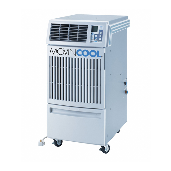
- Page 1 OPERATION MANUAL OFFICE PRO W20 Unit Serial Number Range: 0211XXXXW20 to Present (From February 2011 to Present) READ THIS MANUAL CAREFULLY FOR INSTRUCTIONS ON CORRECT INSTALLATION AND USAGE, AND READ ALL SAFEGUARDS SECCIÓN EN ESPAÑOL SECTION EN FRANÇAIS AVAILABLE AT WWW.MOVINCOOL.COM...
-
Page 2: Serial Number Location And Identification
All rights reserved. This book may not be reproduced or copied, in whole or in part, without the written permission of the publisher. DENSO PRODUCTS AND SERVICES AMERICAS, INC. reserves the right to make changes without prior notice. MovinCool®, Office Pro®, and SpotCool® are registered trademarks of DENSO Corporation. - Page 3 OPERATION MANUAL OFFICE PRO W20...
-
Page 4: Table Of Contents
Table of Contents SERIAL NUMBER LOCATION AND IDENTIFICATION ........2 FOREWORD ...................... 5 Definition of Terms................5 GENERAL WARNINGS & CAUTIONS.............. 6 INVENTORY....................... 7 INSTALLATION ....................8 Choosing an Installation Site ............... 8 Moving the Unit ..................9 Water Pipe or Hose Connection............10 Plugging in the Unit................ -
Page 5: Foreword
FOREWORD Congratulations on purchasing the MovinCool portable air conditioner. This manual explains how to install and operate the MovinCool Office Pro W20 portable air conditioning unit. Please read this operation manual thoroughly to familiarize yourself with the features of the unit and to ensure years of reliable operation. -
Page 6: General Warnings & Cautions
Repair to electrical components by non-certified technicians may result in personal injury and/or damage to the unit. All electrical components replaced must be genuine MovinCool parts, purchased from an authorized reseller. 2. The power supply for this unit should be a dedicated single outlet circuit with UL recognized short-circuit and ground-fault protective breaker. -
Page 7: Inventory
INVENTORY After unpacking your MovinCool unit, please check to make sure you have the following items: 1. Office Pro W20 MovinCool Unit (1) 2. Operation Manual/Product Registration (1) 3. Garden Hose Adapter (2) Note: If any of these items were not included in the box or appear damaged, please contact your MovinCool reseller for replacement. -
Page 8: Installation
INSTALLATION Choosing an Installation Site CAUTION: Following are some precautions to consider before choosing your installation site. Please review carefully as improper installation may result in personal injury or damage to the unit. 1. Do not use the unit in areas where leakage of flammable gas may occur. 2. -
Page 9: Moving The Unit
INSTALLATION (cont.) Moving the Unit Unlock the casters and push the MovinCool unit using the side handles to a flat, level surface and set the casters back to the LOCKED position. Right Side Handle Left Side Handle ILL00043-00 UNLOCKED LOCKED... -
Page 10: Water Pipe Or Hose Connection
WARNING: Before plugging in the unit, connect the water line to the unit. To avoid electrical shock, make sure that there is no water splashed onto the electrical box or the power cord. Office Pro W20 unit has two female 1/2 inch NPT (National Pipe Thread) water connections. CONNECTION TYPE... - Page 11 INSTALLATION (cont.) Water Pipe or Hose Connection (cont.) Connecting Water Pipes (cont.) 4. Make sure that water pipes are connected properly to the unit, and there is no water leakage. CAUTION: Supply water pressure limitation of the unit is maximum 150 psi (1,034 kPa).
- Page 12 INSTALLATION (cont.) Water Pipe or Hose Connection (cont.) Connecting Optional Water Hoses (cont.) 4. Connect the optional water hoses to the garden hose adapters. Hold the hose- end connector with the wrench B tightly to prevent hose rotation. Then tighten the swivel nut with the wrench A.
-
Page 13: Plugging In The Unit
1. Make sure the AC outlet is free of dirt, dust, oil, water, or any other foreign matter. 2. The Office Pro W20 is equipped with UL recognized LCDI cord and NEMA plug configuration (5-15). The appropriate outlet must be used for this plug type. -
Page 14: Warning Signal Connection (Output Signal Terminal L+ And L-)
INSTALLATION (cont.) Warning Signal Connection (Output Signal Terminal L+ and L-) The controller is equipped with a warning signal output relay type (Form C, normal open dry contact) which can be used to monitor the failure conditions. Relay contactor is closed when any of the following conditions has occurred: a. -
Page 15: Fire Alarm Control Panel Connection (Input Signal Terminal E+ And E-)
INSTALLATION (cont.) Fire Alarm Control Panel Connection (Input Signal Terminal E+ and E-) The controller is equipped with a normal open input signal connection, which can be connected directly from the fire alarm control panel. This input signal terminal should only be connected to a close or open dry contact signal. When receiving the signal from the fire alarm control panel, the unit turns off and does not turn back on until it has been RESET. -
Page 16: Lcdi Power Cord Instruction
INSTALLATION (cont.) LCDI Power Cord Instruction WARNING: The LCDI device is a non-serviceable device. Attempting to open the device may expose the user to the hazards of electric shock, and could void warranties of this product. Manufacturer's reliability is limited to the replacement of the device. CAUTION: 1. -
Page 17: Features
FEATURES 1. A digital electronic control panel, which allows the user to easily control the unit’s operation. 2. Dual fan speeds (either HIGH or LOW) in both COOL and FAN ONLY modes. 3. Digital LCD display with blue backlight that indicates: a. -
Page 18: Operation
OPERATION Control Panel Before operating the unit, it is important to familiarize yourself with the basic controls located on the control panel. ILL00052-00 1. COOL Mode Button Activates/deactivates the COOL mode and turns the unit off. 2. FAN Mode Button Activates/deactivates the high, low, and off fan speed. -
Page 19: Lcd Indicators
OPERATION (cont.) Control Panel (cont.) LCD Indicators ILL00053-00 9. MO...SU Illuminates to indicate selected day of the week. 10. °C or °F Temperature displayed in either Fahrenheit or Celsius (see Note). 11. AM/PM Illuminates to indicate AM or PM time of day. 12. -
Page 20: Operating Modes
OPERATION (cont.) Operating Modes The Office Pro W20 can be operated in two modes, FAN ONLY and COOL. When in FAN ONLY mode, the unit circulates the surrounding air. When in COOL mode, the compressor is operated and cool air is circulated. -
Page 21: Set Clock
OPERATION (cont.) Set Clock Prior to operating the Office Pro W20 users should set the clock of the controller to the correct time as shown in the following steps: 1. Press and hold the SET CLOCK button for 3 seconds or until beep. -
Page 22: Operating In Fan Only Mode
OPERATION (cont.) Operating in FAN ONLY Mode 1. The unit can also be operated in FAN ONLY mode by pressing FAN HI/LO button (LCD indicates “FAN HI/LO” and “COOL OFF”). 2. The unit can then be turned off by pressing the FAN HI/LO button until fan turns off (FAN ONLY mode speed sequences are HI→LO→OFF). -
Page 23: How To Set A Program
OPERATION (cont.) How to Set a Program SET START TIME 1. Press and hold the SET PROG button for 3 seconds or until beep. 2. Press SET TEMP buttons to scroll day of the week. 3. Press ENTER button. Step 1 & 18 4. -
Page 24: How To View And Delete Program
OPERATION (cont.) How to View and Delete Program 1. Press and hold the SET PROG button for 3 seconds or until beep. 2. To view edited program - While pressing and holding the SET PROG button, press SET TEMP buttons ( ) to scroll program sequence. -
Page 25: Self-Diagnostic Codes
The unit returns to the normal operation after the problem is fixed and the controller is RESET. To RESET: Press FAN HI/LO and COOL ON/OFF buttons simultaneously for 5 seconds. Contact your MovinCool reseller or a qualified technician if problem persists. -
Page 26: Empty The Drain Tank
OPERATION (cont.) Empty the Drain Tank During COOL mode, condensate water accumulates in the drain tank. When the drain tank becomes full, the “TANK FULL” LED flashes and the LCD displays “TANK FL” and the unit turns off automatically. Note: If you want to empty the drain tank, while the unit is in operation, press the COOL ON/OFF button to turn the unit off. -
Page 27: Condensate Pump Kit (Optional)
OPERATION (cont.) Condensate Pump Kit (Optional) A condensate pump kits are available to allow continuous operation and to eliminate the need for a drain tank. When the water collects to level (A) in the pump reservoir, the condensate pump begins to operate and discharge the water. -
Page 28: Inspection & Maintenance
INSPECTION & MAINTENANCE Empty the Drain Tank To empty the drain tank, refer to instructions on page 26. Clean the Air Filter Clean the air filter once a week. If the unit is used in a dusty environment, more frequent cleaning may be required. A dirty air filter can reduce air output resulting in a decrease in the cooling capacity. -
Page 29: Water Regulating Valve
INSPECTION & MAINTENANCE (cont.) Water Regulating Valve This unit is equipped with a water regulating valve to operate within wide water temperature range. This water regulating valve automatically controls the water flow rate to stabilize the refrigeration system and it has an adjusting bolt to adjust the valve opening temperature. - Page 30 INSPECTION & MAINTENANCE (cont.) Water Regulating Valve (cont.) Adjustment of Water Regulating Valve Setting 1. Stop the unit and unplug the power cord. Then shut off the water supply. 2. Remove five (5) screws from the service panel on the rear side of the unit. SCREWS (5) ILL00156-00 3.
- Page 31 INSPECTION & MAINTENANCE (cont.) Water Regulating Valve (cont.) Adjustment of Water Regulating Valve Setting (cont.) 6. Rotate the adjusting bolt with a wrench to adjust the valve temperature setting according to the “Valve Setting Guide Table” on page 32. The painted line on adjusting bolt and housing is for rotational reference to complete one rotation (360°).
- Page 32 INSPECTION & MAINTENANCE (cont.) Water Regulating Valve (cont.) Adjustment of Water Regulating Valve Setting (cont.) 7. Write the value setting with a permanent marker on the adjustment record table on the inside panel of the unit. Note: Recording the value setting is very important for reference when making future adjustments.
-
Page 33: In-Season/Off-Season Inspection & Maintenance
2. Check the power cord, plug and prongs for damage or excess play. If any damage or excess play is found, contact your MovinCool reseller or a qualified technician for repair. -
Page 34: Troubleshooting
TROUBLESHOOTING Check the following conditions before calling your MovinCool reseller or a qualified technician. CONDITION POSSIBLE CAUSE REMEDY Unit does not operate. 1. Ground fault breaker trip or Reset breaker or reset power LCDI power cord trip. cord. 2. Drain tank is full. -
Page 35: Technical Specifications
TECHNICAL SPECIFICATIONS ITEM SPECIFICATIONS Electronic Features Operation Digital Programmable Electrical Characteristics Voltage Requirement Single-Phase, 115 V, 60 Hz Operating Voltage Max. 127 V Range Min. 104 V Recommended Fuse Size 15 A Cooling Capacity and Power Consumption Air: 80 °F (27 °C), 50 %RH Total Cooling Capacity 15,700 Btu/h (4,590 W) Water (EWT/LWT): 85 °F /95... - Page 36 TECHNICAL SPECIFICATIONS (cont.) ITEM SPECIFICATIONS Operating Condition Range Inlet Air Max. 95 °F (35 °C), 60 %RH Temperature Min. 65 °F (18 °C), 50 %RH Entering Water Max. 90 °F (32 °C) Temperature Min. 40 °F (4.4 °C) Water Pressure 150 psi (1,034 kPa) or less Recommended Water 5 gal/min (18 L/min)
-
Page 37: Warranty Statement
Office Pro W20 Warranty: 3 Years with warranty registration OR 1 Year for unregistered units. DENSO shall, at its sole discretion, repair or replace any defective product covered by this warranty. - Page 38 P/N: GX484007-3313EN Fourth Issue: April 2015...
Need help?
Do you have a question about the Office Pro W20 and is the answer not in the manual?
Questions and answers