
Related Manuals for Steel City 40540


Summary of Contents for Steel City 40540
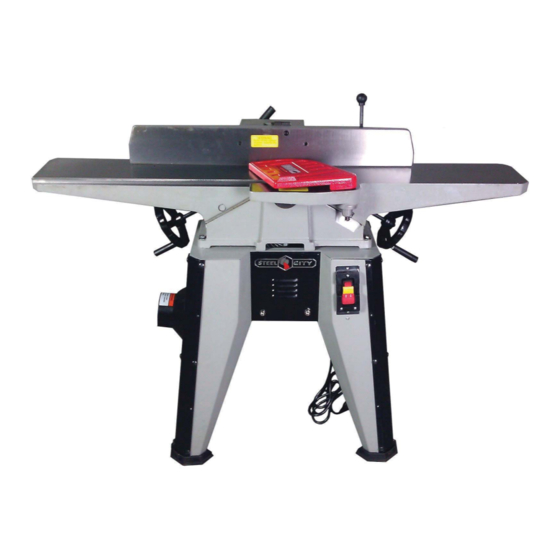
- Page 1 ® User Manual Read and understand this manual before using machine. 6” CAST IRON JOINTER Model Number 40540 STEEL CITY TOOL WORKS VER. 01.29.14...
-
Page 3: Table Of Contents
The drawings, illustrations, photographs, and specifications in this user manual represent your machine at time of print. However, changes may be made to your machine or this manual at any time with no obligation to Steel City Tool Works. -
Page 4: Product Specifications
40919 Knives (3 Pack) There are a variety of accessories available for your Steel City Product. For more information on any accessories associated with this and other machines, please contact your nearest Steel City distributor, or visit our website at: www.steelcitytoolworks.com... -
Page 5: Feature Identification
FEATURE IDENTIFICATION Fence (REAR VIEW) Depth Gauge Table Adjustment Handwheel Infeed Table Outfeed Table Power Switch G. Cutterhead Guard Rubber Foot Power Cord Dust Port Belt Guard Lock Knob/Fence Tilt Lock Handle/Fence Lock Handle... -
Page 6: Product Safety
PRODUCT SAFETY 1. Serious personal injury may occur if normal safety 10. USE accessories only recommended by Steel City. precautions are overlooked or ignored. Accidents 11. DO NOT pull the jointer by the power cord. NEVER are frequently caused by lack of familiarity or failure allow the power cord to come in contact with sharp to pay attention. -
Page 7: General Safety
GENERAL SAFETY WARNING WARNING TO AVOID serious injury and damage to the machine, read and follow all Safety and Operating Instructions before assembling and operating this machine. This manual is not totally comprehensive. It does not Exposure to the dust created by power sanding, saw- and can not convey every possible safety and opera- ing, grinding, drilling and other construction activities tional problem which may arise while using this... - Page 8 11. DO NOT FORCE the machine to perform an opera- WARNING tion for which it was not designed. It will do a safer and higher quality job by only performing operations for which the machine was intended. 12. DO NOT stand on a machine. Serious injury could result if it tips over or you accidentally contact any 3.
-
Page 9: Electrical Requirements
25. USE ONLY recommended accessories. Use of 28. SAVE these instructions and refer to them frequent- incorrect or improper accessories could cause seri- ly and use them to instruct other users. ous injury to the operator and cause damage to the 29. -
Page 10: Grounding Instructions
GROUNDING INSTRUCTIONS EXTENSION CORDS WARNING WARNING This machine MUST BE GROUNDED while in use to protect the operator from electric shock. To reduce the risk of fire or electrical shock, use the In the event of a malfunction or breakdown, GROUND- proper gauge of extension cord. -
Page 11: Unpacking & Inventory
“ON” after all the parts have been moving parts. Lay out all parts on a clean work surface. obtained and installed correctly. For missing parts, Remove any protective materials and coatings from all of the contact Steel City at 1-877-SC4-TOOL. PARTS QTY. PARTS QTY. -
Page 12: Assembly
ASSEMBLY LEG ASSEMBLY With assistance, remove bed from carton and place upside down and protect the bed by using the styrofoam (FIG.1). Locate hardware (FIG.2). Match leg sections black with grey. Use detents to assist in matching. Shown in FIG.3, 3A, 3B. Place carriage bolts through backside of the black leg support and lay the grey leg on top, then screw on nuts (FIG.3 (X,Y)). - Page 13 MOTOR MOUNT BRACKET ASSEMBLY Locate the front and rear motor bracket supports, black and grey. FIG.6 is rear with hole for motor pulley to protrude. Install belt guard bolts, FIG.6A into 2 holes, (FIG.6 (D)). One shown tightened. Install 2 carriage bolts each side of motor support brackets, black and grey. Grey is shown in FIG.7 and FIG.7A (A,B). Hand tighten nuts to keep secure for future use.
- Page 14 MOTOR ASSEMBLY TO LEGS Using stand hardware from FIG.2, line up the left and/or right leg assembly with the upside down motor assembly. Press leg assembly onto the carriage bolt left in place (FIG.7 and 7A). (FIG.10 and FIG.10A) Install the nut (C) onto carriage bolt (D) and tighten the one closest to the motor bracket (FIG.10B) Install the other carriage bolt from opposite side, place nut on carriage bolt and leave loose for the cross support bracket install.
- Page 15 SWITCH INSTALL Using screws and nuts, (FIG.12 (A,B)) mount switch (FIG.12A) into right leg. Insert screws from front side and nuts on rear. Tighten at this time. FIG.12 FIG.12A...
- Page 16 DUST COLLECTION AND STAND INSTALL With the bed upside down, install the dust collection adapter and dust hose to the chip catcher under the cutterhead using 4 Phillips screws (FIG.13 and 13A (X,Y,Z)). Place support plate (W) (FIG.13B) onto bed, place hose (B) through opening and line up the 4 slotted holes (A) with holes in the bed.
- Page 17 (continuing dust collection and stand install) FIG.17 FIG.18 FIG.19 FIG.19A FIG.21 FIG.20 FIG.22 NOTE: FIG.18 and 20 may not be as shown. Your unit may have a longer hose and eliminated adapter. Steps 7-9 page 14.
- Page 18 BELT TENSION AND GUARD With the machine still upside down, install the belt onto both pulleys (FIG.23 (A)). With help, flip the machine onto the 4 rubber feet. Pull down on the motor bracket assembly (FIG.23B). Fig.23A (B) belt is shown as tightened. With belt fully tight, then tighten silver cap nuts (FIG.23C (C)) on the rear and the 2 on the front of the jointer.
- Page 19 CRANK HANDLE INSTALL Take handle assembly (A) (FIG.24) and place over (D) so that the spring pin (E) is in the slots of the handle (arrow). Take Allen screw (C) (FIG.24A) and place washer (B) over and insert into the end of the rod and tighten. Repeat for other side.
- Page 20 FENCE INSTALL Thread the Allen bolts (A) with flat (B) and lock (C) washers into the rear of the bed (FIG.26). Position carriage slots over each bolt and level to infeed table, then tighten. Line up the pointed set screws (FIG.27 (A)) with the fixed adjustable receiver (B) and make each side snug and then tighten the nut (C) fit 27A.
- Page 21 GUARD INSTALL Turn the spring assembly counter clockwise (FIG.30) and drop the red guard assembly into the spring assembly from the top (FIG.31). With the guard installed through the spring assembly (FIG.32) and resting against the fence, insert the screw (FIG.33 (A)). FIG.31 FIG.30 FIG.32...
-
Page 22: Adjustments
ADJUSTMENTS INFEED TABLE ADJUSTMENT FIG.4 FIG.5 For safety, unplug from power source (FIG.4(C)), remove yellow key from under the red paddle (FIG4(D)). To raise or lower the infeed table, make sure the tables coplanar and that the pointer is at zero (FIG.4(A)). If beds are level and pointer is off, loosen the 2 small screws (FIG.4(E)) to shift the pointer to 0. -
Page 23: Operations
OPERATIONS According to many OSHA, ANSI, STATE, and LOCAL WARNING CODES, it is the Employers Responsibility to: PERMIT ONLY trained and authorized employees to operate equipment. INSPECT AND MAINTAIN guards, safety devices CHILDPROOF THE WORKSHOP AREA by and start/stop controls. removing switch keys, unplugging tools from the INSTRUCT, TRAIN and SUPERVISE the safe method electrical receptacles, and using padlocks if necessary. -
Page 24: Jointing An Edge
The following directions will give the beginner a start on jointer operations. Use scrap pieces of lumber to check settings and to get the feel of the operations before attempting regular work. PLACEMENT OF HANDS JOINTING AN EDGE DURING FEEDING This is the most common operation for the jointer. -
Page 25: Taper Cuts
SURFACING TAPER CUTS One of the most useful jointer operations is cutting an Surfacing is identical to the jointing operation except for edge to a taper. This method can be used on a wide the position of the workpiece. For surfacing, the major variety of work. -
Page 26: Maintenance
WARNING Repairs to the jointer should be performed by trained personnel only. Contact your nearest Steel City Dealer for authorized service. Unauthorized repairs or replace- ment with non-factory parts could cause serious injury to the operator and damage to the jointer. -
Page 27: Troubleshooting
TROUBLESHOOTING GUIDE Motor and Machine Operation Motor will not start. a t l n i l a t l 2. Open circuit in motor or loose connections. 2. Inspect all lead connections on motor for loose or open connections. Fuses or circuit 1. - Page 28 Cutting Excessive snipe g i l h t i e f i (gouge in the end of 2. Operator pushing down on end of workpiece. 2. Reduce/eliminate downward pressure on that end of workpiece. the board that is uneven with the rest of the cut).
- Page 29 DATE MAINTENANCE PERFORMED REPLACEMENT COMPONENTS REQUIRED...
- Page 30 DATE MAINTENANCE PERFORMED REPLACEMENT COMPONENTS REQUIRED...
- Page 31 ® STEEL CITY TOOL WORKS www.steelcitytoolworks.com 1-877-SC4-TOOL (1-877-724-8665)
Need help?
Do you have a question about the 40540 and is the answer not in the manual?
Questions and answers