
Related Manuals for Steel City 40-300


Summary of Contents for Steel City 40-300
- Page 1 MAnUAL 17’’, 12-SPEED DRILL PRESS 40-300 / 40-310 40-300 40-310 For technical support, provide the following model and serial numbers: Model No: ______________________ Serial No: ______________________...
- Page 2 The manufacturer warrants its machines to be free from defects in workmanship and materials for a period of 2 years from the date of the original purchase for Steel City shop machines or for a period of 1 year for Titanium production machines;...
-
Page 3: Table Of Contents
The drawings, illustrations, photographs, and specifications in this user manual represent your machine at time of print. However, changes may be made to your machine or this manual at any time with no obligation to Steel City. ProDUCT sPeCIFICATIons 40-300 / 40-310S1 Model Motor 3/4 HP - 110V - 1 ph - 12A Drilling capacity 3/4”... -
Page 4: Safety
sAFeTY This manual is not totally comprehensive. It does not and can not convey every possible safety and operational problem which may arise while using this machine. The manual will cover many of the basic and specific safety procedures needed in an industrial environment. wArnInG All federal and state laws and any regulations having jurisdiction covering the safety requirements for use of this... - Page 5 22. Do noT operate any machine or tool if under the 4. Prevent electrical shock. Follow all electrical and safety codes, including the National Electrical Code (NEC) and influence of drugs, alcohol, or medication. the Occupational Safety and Health Regulations 23.
-
Page 6: Product Safety
ProDUCT sAFeTY 1. Do not try to drill a workpiece that is too small to be 5. Securely lock the head and table to the column, and the securely held to the table or in a vise. table to the table support before operating the drill press. 2. -
Page 7: Electrical And Grounding Instructions
eLeCTrICAL AnD GroUnDInG InsTrUCTIons wArnInG IMProPer eLeCTrICAL ConneCTIon equipment-grounding conductor can result in risk of electric To reduce the risk of electric shock, follow all shock. The conductor with the green insulation (with or electrical and safety codes, including the without yellow stripes) is the equipment-grounding National Electric Code (NEC) and the conductor. -
Page 8: Unpacking And Inventory
Be aware of missing or damaged parts to inform your supplier as soon as possible. 1. Base (40-300 or 40-310) 2. Column and rack (40-300 or 40-310) 3. Hex bolts and lock washers (4) 4. Table bracket assembly 5. Table handle 6. -
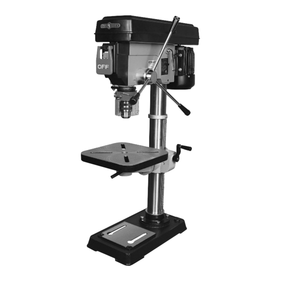
Page 9: Feature Identification
FeATUre IDenTIFICATIon Cast-iron pulleys High quality cast-iron construction Forced opening line interrupter switch Adjustable tension spindle return spring Positive depth stop Chuck guard swing away type Cast-iron tilt table -45° 0° +45° Page 9... -
Page 10: Assembly
AsseMBLY ◊ seCUre THe TABLe onTo THe wArnInG TABLe BrACKeT Make sure the switch is in the off position and Attach the table handle on the worm gear and tighten the machine is unplugged. the set screw. ◊ ATTACH THe CoLUMn To THe BAse Place the base on a flat level and stable surface and bolt the column using the 4 hex bolts and washers. - Page 11 ◊ reMoVInG THe CHUCK AnD wArnInG sPInDLe To prevent the risk of injuries, always cover the wArnInG chuck and drill bit with the chuck guard while using. Make sure the switch is in the off position and the machine is unplugged. A wedge is included with the machine, to help in ◊...
-
Page 12: Adjustments
ADJUsTMenTs wArnInG ◊ ADJUsTInG TABLe roTATIon Make sure the switch is in the off position and Loosen the table lock handle (3). the machine is unplugged. Rotate the table to the desired position. Tighten the table lock handle (3) before using. ◊... - Page 13 ◊ ADJUsTInG reTUrn sPrInG The drill chuck will automatically return slowly to its original position when pressure on the feed handle is released. note: Always use hand on feed handle to return to position. Failure to do will break the spring. The return spring is adjusted at the factory.
- Page 14 PArT LIsTs 40-300 / 40-310S1 40-310S1 Page 14...
-
Page 15: Parts List
PARTS LIST FOR 40-300 - BENCH TOP PART N0. DESCRIPTION 40300-01 GUARD COVER 40300-02 PAN HEAD SCREW 40300-04 40300-05 SPINDLE PULLEY 40300-06 V-BELT 40300-07 MIDDLE PULLEY 40300-08 BALL BEARING 40300-09 RETAINING RING 40300-10 MOTOR PULLEY 40300-11 V-BELT 40300-12 SET SCREW... - Page 16 PARTS LIST FOR 40-300 - BENCH TOP PART N0. DESCRIPTION 40300-41 ADJUSTMENT LEVER 40300-42 LEVER SHAFT ASS'Y 40300-43 SET SCREW 40300-44 RETAINING RING 40300-45 MOTOR SUPPORT BRACKET 40300-46 MOTOR SUPPORT BRACKET 40300-47 ELECTRICAL CORD 40300-48 STRAIN RELIEF 40300-49 SPRING WASHER...
- Page 17 PARTS LIST FOR 40-300 - BENCH TOP PART N0. DESCRIPTION 40300-80 GEAR 40300-81 BOLT CLAMP 40300-82 TABLE ARM BRACKET 40300-83 GEAR SHAFT 40300-84 SET SCREW 40300-85 SLEEVE AND ROD ASS'Y 40300-86 TABLE BRACKET 40300-87 SET SCREW 40300-88 TABLE LOCK HANDLE...
- Page 18 PARTS LIST FOR 40-310 - FLOOR MODEL PART N0. DESCRIPTION 40310-01 GUARD COVER 40310-02 PAN HEAD SCREW 40310-04 40310-05 SPINDLE PULLEY 40310-06 V-BELT 40310-07 MIDDLE PULLEY 40310-08 BALL BEARING 40310-09 RETAINING RING 40310-10 MOTOR PULLEY 40310-11 V-BELT 40310-12 SET SCREW 40310-13 SCREW 40310-13-1...
- Page 19 PARTS LIST FOR 40-310 - FLOOR MODEL PART N0. DESCRIPTION 40310-41 ADJUSTMENT LEVER 40310-42 LEVER SHAFT ASS'Y 40310-43 SET SCREW 40310-44 RETAINING RING 40310-45 MOTOR SUPPORT BRACKET 40310-46 MOTOR SUPPORT BRACKET 40310-47 ELECTRICAL CORD 40310-48 STRAIN RELIEF 40310-49 SPRING WASHER 40310-50 40310-51 HEX HEAD SCREW...
- Page 20 PARTS LIST FOR 40-310 - FLOOR MODEL PART N0. DESCRIPTION 40310-80 GEAR 40310-81 BOLT CLAMP 40310-82 TABLE ARM BRACKET 40310-83 GEAR SHAFT 40310-84 SET SCREW 40310-85 SLEEVE AND ROD ASS'Y 40310-86 TABLE BRACKET 40310-87 SET SCREW 40310-88 TABLE LOCK HANDLE 40310-89 WASHER 40310-90...