
Related Manuals for Steel City 30-200


Summary of Contents for Steel City 30-200
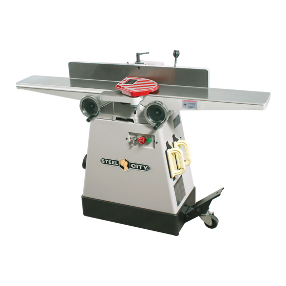
- Page 1 OWNER’S MANUAL 6” JOINTER 30-200 Should you require assistance, please have available your: Model no.: ________________________ Serial no.: ________________________ VER.2017-08-en...
-
Page 2: Table Of Contents
The drawings, illustrations, photographs, and technical specifications in this user manual represent your machine at time of print. However, changes may be made to your machine or this manual at any time with no obligation to Steel City. Page 2... -
Page 3: Warranty
The manufacturer warrants its machines to be free from defects in workmanship and materials for a period of 2 years from the date of the original purchase for Steel City shop machines or for a period of 1 year for Titanium production machines;... -
Page 4: Technical Specifications
TECHNICAL SPECIFICATIONS Motor ..........1 HP, 110 V Table height........7 ¼’’ x 55 ¾’’ (185 x 1405 mm) Working height .......30 ¾’’ (780 mm) Max. cutting width ......6’’ (152 mm) Max. cutting depth......½’’ (13 mm) Rabbeting capacity......½’’ (13 mm) Fence size........4’’ x 32 ½’’ (102 x 830 mm) Cutterhead speed......5000 rpm Tool holder dia........Ø... -
Page 5: General Safety
GENERAL SAFETY WARNING WARNING TO AVOID serious injury and damage to the machine, read and follow all Safety and Operating Instructions before assembling and operating this machine. Exposure to the dust created by power sanding, sawing, grinding, drilling and other construction activities may This manual is not totally comprehensive. - Page 6 WARNING 15. ALWAYS keep hands and fingers away from the blades when operating. 16. DO NOT FORCE the machine to perform an TO REDUCE the risk of electrical shock. DO NOT use operation for which it was not designed. It will do a safer this machine outdoors.
-
Page 7: Product Safety
26. KEEP protective guards in place and in working order. into the moving parts. Users must wear a protective cover on their hair, if the hair is long, to prevent it from 27. Check material for loose knots, nails and other defects. contacting any moving parts. -
Page 8: Electrical And Grounding Instructions
ELECTRICAL AND GROUNDING INSTRUCTIONS PLUGS/RECEPTACLES WARNING WARNING To reduce the risk of electric shock, follow all electrical and MAKE SURE the circuit breaker does not exceed the safety codes, including the National Electric Code (NEC) rating of the plug and receptacle. and the Occupational Safety and Health Regulations (OSHA). -
Page 9: Unpacking And Inventory
SCREW .................2 FOOT PAD ...............2 KNIFE-HOLDER / CHIP-BREAKER......2 HEX NUT M8*1.25P (13B*6.5H) ........4 CARBIDE INSERT (STANDARD) ........2 CASTER ................2 CARBIDE INSERT (FOR RABBETING)......1 LIVE CASTER..............1 Not supplied with model 30-200 HS1 / Supplied with model 30-200 HS1 only Page 9... -
Page 10: Assembly
ASSEMBLY CASTERS 1. Place the stand up side down on the floor and use the 2. Place a caster in the center of a braket and align both cardboard to protect from scratching. braket caster hole. 3. Put M8 hex screw and fix the hex nut. 4. - Page 11 MOUNTING JOINTER TO BASE 2. Install a V-belt in the groove on the cutterhead pulley D. Fig. 4 Note: should you decide to install the caster assembly , proceed now and follow instructions in the box. 1. Using a hoist or with the help of appropriate number of people, lift the jointer bed onto the base.
- Page 12 CHECK BELT TENSION ATTACH FENCE CARRIAGE ASSEMBLY 1. The belt should not deflect more than ½’’ (13 mm) when squeezed at its midpoint. WARNING 2. If needed, tighten the belt by loosening the 4 motor mounting bolts and applying a downward pressure on the MAKE CERTAIN THAT THE MACHINE IS motor then re-tighten the bolts.
- Page 13 CUTTERHEAD GUARD INSTALLATION THE TABLE HEIGHT ADJUSTMENT HANDWHEELS INSTALLATION 1. Remove the screw (A) from the post of the cutterhead guard (B). Fig. 12 2. Turn and hold the tension adjustment knob and fit the 1. Fit the 2 table height adjustment handwheels (A) on the shaft as far down as it will go into the mounting hole on shafts at the front of the jointer.
-
Page 14: Adjustments
ADJUSTMENTS INFEED TABLE ADJUSTMENT OUTFEED TABLE ADJUSTMENT The outfeed table must be EXACTLY level with the knives The depth of cut is reached by raising or lowering the infeed when they are at their highest point of revolution. The height Fig. - Page 15 ADJUST FENCE AND 1. To set the 45° outward fence stop, use a combination or POSITIVE STOPS machinist square and set the fence to 45° outward. Fig. 25 The fence on this jointer is equipped with positive 2. Loosen the jam nut (H) on the 45° outward fence stop stops at specific pre-set angles.
-
Page 16: Maintenance
CUTTERHEAD KNIVES The straight knife cutterhead offers 2 methods of adjustment: springs and jack screws (Fig. 29). MODEL 30-200: There are 3 knives (A) installed in the cutterhead at the This provides you with 2 options for setting the knives, so factory. - Page 17 5. Fig. 31 shows the knife C and the knife locking bar D removed from the cutterhead. Remove the remaining two knives and locking bars, in the same manner. Fig. 33 12. Lock the outfeed table in position and remove the feeler gauge.
- Page 18 Fig. 38 HELICAL CUTTERHEAD INSERT 6. Repeat with all the other inserts. REVERSAL / REPLACEMENT MODEL 30-200 H: IMPORTANT: 1. Using one of the supplied Allen keys, loosen but do not DO NOT REMOVE the nut and screw that secure the remove the nut and screw A and remove the knife knife holder/chip breaker, ONLY LOOSEN.
- Page 19 Fig. 39 clockwise so it pops out and releases the stop button. The left -key (E) will prevent any starting up if inserted key is not in position of function. Fig. 39 MODEL 30-200 AND 30-200H ELECTRICAL CIRCUIT BLACK BLACK WHITE...
-
Page 20: Troubleshooting Guide
TROUBLESHOOTING GUIDE Motor and Machine Operation PROBLEM LIKELY CAUSE(S) SOLUTION Motor will not start. 1. Low voltage. 1. Check power line for proper voltage. 2. Open circuit in motor or loose 2. Inspect all lead connections on motor for connections. loose or open connections. - Page 21 Cutting PROBLEM LIKELY CAUSE(S) SOLUTION Excessive snipe 1. Outfeed table is set too low. 1. Align outfeed table with cutterhead knife at top dead center. (gouge in the end of 2. Operator pushing down on end of workpiece. 2. Reduce/eliminate downward pressure on that end of workpiece. the board that is uneven with the rest of the cut).
-
Page 22: Parts List
PARTS LIST Model 30-200 / MACHINE Page 22... - Page 23 PARTS Model 30-200 / BASE 108.1 137.1 137.2 108.2 Page 23...
- Page 24 HELICAL CUTTER HEAD Model 30-200 H ONLY REF N0. PART N0. DESCRIPTION SPECIFICATION CUTTER HEAD S30200H02 SCREW S30200H03 S30200H04 KNIFE-HOLDER / CHIP-BREAKER SCM32210 CARBIDE INSERT (STANDARD) 30X12X1.5MM (T) SCM32220 CARBIDE INSERT (RABBETING) 30X12X1.5MM (T) S30300115 ALLEN KEY SCM32200H CUTTERHEAD ASSEMBLY (INCL. KEY 1 TO 5)
- Page 25 PARTS LIST ITEM NO PART NO. DESCRIPTION SPECIFICATION S302001 locking bolt S302002 flat washer 13*28*3.0t S302003 locking nut S302004 fence upper bracket S302005 hex. screw S302006 stop plate S302007 flat washer 13.5*40*3.0t S302008 spring pin 4*12 S302009 S3020010 spring pin 4*20 S3020011 fence lower bracket...
- Page 26 40.2 S30200402 spring washer 13*22.7 40.3 S30200403 spring pin 3*25 40.4 S30200404 hex. nut 1/4"-20NC(11B*5.5H) 40.5 S30200405 hex. nut 1/2"-12NC(19.05B*11.11H) 40.6 S30200406 flat washer 10*22*0.8t 40.7 S30200407 spacer 40.8 S30200408 special nut 40.9 S30200409 leadscrew 40.10 S302004010 set screw 40.11 S302004011 40.12 S302004012...
- Page 27 S3020071 steel pin S3020072 set screw 1/4"-20NC*3/4" S3020073 hex. nut 1/4"-20NC(11B*5.5H) S3020074 index frame S3020075 cap screw 5/16"-18NC*3/4" S3020076 index pin S3020077 spring S3020078 spring housing S3020079 steel ball 22*1/4"-20NC S3020080 locking lever S3020081 spring pin 3*20 S3020082 guard assembly S3020083 pointer S3020084...
- Page 28 108.1.3 S3020010813 cord clamp plate 108.1.4 S3020010814 cord retainer SB7R-1 108.1.5 S3020010815 power cord SJT 16AWG*3C*2600mm 108.1.6 S3020010816 messeng cord SJT16AWG*4C*920mm 108.1.7 S3020010817 cord retainer PGA13.5-11B 108,2 S302001082 control switch assembly 108.2.1 S3020010821 switch plate 108.2.2 S3020010822 key switch 108.2.3 S3020010823 stop botton 108.2.4...
- Page 29 Page 29...
- Page 30 Page 30...
- Page 31 NOTES...
Need help?
Do you have a question about the 30-200 and is the answer not in the manual?
Questions and answers