
Related Manuals for Steel City 20520


Summary of Contents for Steel City 20520
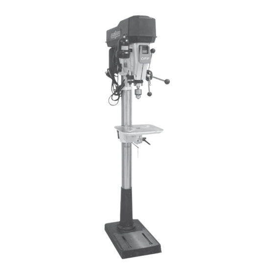
- Page 1 User Manual Read and understand this manual before using machine. 17” DRILL PRESS Model Number 20520 ® STEEL CITY TOOL WORKS Manual Part No. OR71528 VER. 2.07...
-
Page 3: Table Of Contents
The drawings, illustrations, photographs, and specifications in this user manual represent your machine at time of print. However, changes may be made to your machine or this manual at any time with no obligation to Steel City Tool Works. -
Page 4: Warranty
2 YEAR LIMITED WARRANTY Steel City Tool Works, LLC (SCTW) warrants this SCTW machinery to be free of defects in workmanship and materials for a period of 2 years from the date of the original retail purchase by the original owner for domestic use. Granite components are warranted for 2 years based on normal use and is void if non SCTW accessories are used that cause the break or chip. - Page 5 City:______________________________________________ ___ Vacuum Veneer Press ___ Wide Belt Sander Other____________________________________________ How did you first learn of Steel City Tool Works? ___ Advertisement ___ Mail Order Catalog 11. Which benchtop tools do you own? Check all that apply. ___ Web Site...
- Page 6 FOLD ON DOTTED LINE PLACE STAMP SteelCityToolWorks #4 Northpoint Court Bolingbrook, IL 60440 FOLD ON DOTTED LINE...
-
Page 7: Product Specifications
Quill lock ACCESSORIES AND ATTACHMENTS There are a variety of accessories available for your Steel City Product. For more information on any accessories associated with this and other machines, please contact your nearest Steel City distributor, or visit our website at: www.steelcitytoolworks.com. -
Page 8: Definition Of Terms
DEFINITION OF TERMS Belt cover - Can be opened to provide access to belts, Table - Holds work piece. pulleys, and speed chart. Column - Used to support work table and drill press On/Off switch - Access power to drill press or turn head. -
Page 9: Feature Identification
FEATURE IDENTIFICATION Belt cover On/Off switch Feed handles Quill lock Keyed chuck Table G. Column Base Depth scale Motor Flexible lamp... -
Page 10: General Safety
GENERAL SAFETY WARNING WARNING TO AVOID serious injury and damage to the machine, read and follow all Safety and Operating Instructions before assembling and operating this machine. This manual is not totally comprehensive. It does not Exposure to the dust created by power sanding, saw- and can not convey every possible safety and opera- ing, grinding, drilling and other construction activities tional problem which may arise while using this... - Page 11 11. DO NOT FORCE the machine to perform an opera- WARNING tion for which it was not designed. It will do a safer and higher quality job by only performing operations for which the machine was intended. 12. DO NOT stand on a machine. Serious injury could result if it tips over or you accidentally contact any 3.
- Page 12 29. Information regarding the safe and proper operation 25. USE ONLY recommended accessories. Use of of this tool is also available from the following incorrect or improper accessories could cause seri- sources: ous injury to the operator and cause damage to the machine.
-
Page 13: Product Safety
PRODUCT SAFETY 1. Serious personal injury may occur if normal safety 10. USE accessories only recommended by Steel City. precautions are overlooked or ignored. Accidents 11. DO NOT pull the drill press by the power cord. are frequently caused by lack of familiarity or failure NEVER allow the power cord to come in contact to pay attention. -
Page 14: Electrical Requirements
secured by a vise. Prevent the workpiece from 26. NEVER START THE DRILL PRESS BEFORE rotating by clamping it to the table or by securing it CLEARING THE TABLE OF ALL OBJECTS (tools, against the drill press column. Loss of control of the scrap pieces, etc.). -
Page 15: Grounding Instructions
GROUNDING INSTRUCTIONS EXTENSION CORDS WARNING WARNING This machine MUST BE GROUNDED while in use to protect the operator from electric shock. To reduce the risk of fire or electrical shock, use the In the event of a malfunction or breakdown, GROUND- proper gauge of extension cord. -
Page 16: Unpacking & Inventory
For missing parts, Remove any protective materials and coatings from all contact Steel City at 1-877-SC4-TOOL. of the parts and the drill press. The protective coatings A. Drill press head and motor assembly. B. Base C. - Page 17 A. Keyed chuck B. Spindle adapter remover C. Chuck key D. Hex head screws(2), with flat washer(4),and hex nuts(2) (accessory hardware) E. Light assembly clamp, hex socket head screws(2), and lock washer(2) (plastic sleeve not show) F. Table raise/lower handle G.
-
Page 18: Assembly
ASSEMBLY 2. Loosen set screw (E) and remove ring (D) from the WARNING column. SEE FIG 7A. • The drill press is a heavy machine; two people may 3. Place Table Bracket Assembly (F) over top of be required for certain assembly operations. column making sure the notch in the side of the bracket matches up with the rack (G). - Page 19 Fig. 10 Fig. 12 2. Align the drill press head with the table and base and tighten the two head locking screws (C). 7. Assemble the threaded end of the table rotation SEE FIG. 12. lock handle (M ) into hole (N) in the front, right side Fig.
- Page 20 FASTENING DRILL PRESS 4. Before chuck and spindle installation, make certain that the spindle taper (E) and the tapered hole in the chuck (F) are clean and free of grease, lacquer, Fig. 17 or rust preventive coating. SEE FIG. 14, page 18. Fig.
-
Page 21: Adjustments
ADJUSTMENTS 4. The table (E) can be rotated 360 degrees by loos- WARNING ening the table rotation lock handle (D) and rotating the table to the desired position, then tighten the MAKE CERTAIN that the drill press is disconnected handle. from the power source. -
Page 22: Drilling Holes To Depth
DRILL SPEEDS DRILLING HOLES TO DEPTH WARNING WARNING MAKE CERTAIN the drill press is disconnected from MAKE CERTAIN the drill press is disconnected from the power source. the power source. Sixteen drill speeds (215, 310, 340, 450, 490, 510, 600, Fig. - Page 23 ADJUSTING RETURN SPRING INSTALLING AND REMOVING DRILL BITS The drill chuck will automatically return slowly to its upper position when the handle is released. The return WARNING spring was properly adjusted at the factory. However, to adjust, if necessary: MAKE CERTAIN the drill press is disconnected from the power source.
- Page 24 REMOVING THE CHUCK ADJUSTING THE SPLIT HEAD AND SPINDLE CASTING WARNING WARNING MAKE CERTAIN the drill press is disconnected from MAKE CERTAIN the drill press is disconnected from the power source. the power source. NOTE: The Head Casting and quill have been adjusted 1.
-
Page 25: Operations
OPERATIONS FLEXIBLE LAMP WARNING • DO NOT expose the drill press to rain or operate the WARNING in damp locations. To reduce the risk of fire, use only 40 watt or less, 120 • MAKE SURE all parts have been assembled correctly volt, light bulb (not supplied). -
Page 26: Correct Drilling Speeds
Fig. 28 DRILLING METAL WARNING NEVER hold the workpiece in your bare hands. ALWAYS use clamps or vises to hold your workpiece. Twist drill bits should only be used in drilling metals. Never hold the workpiece in your bare hands; always use clamps or vises. -
Page 27: Changing Motor Voltage
CHANGING MOTOR VOLTAGE 1. Make sure switch is OFF and disconnect power cord from power source. WARNING 2. Verify on the motor tag that motor is dual voltage. MAKE CERTAIN to disconnect the machine from the power source before working on motor. 3. -
Page 28: Maintenance
MAINTENANCE LUBRICATION CLEANING With the drill press unplugged, blow off motor with low- WARNING pressure air to remove dust or dirt. Air pressure above Turn the power switch OFF and unplug the power cord 50 P. S. I. should not be used as high-pressured air from its power source. -
Page 29: Troubleshooting
TROUBLESHOOTING GUIDE TO PREVENT INJURY TO YOURSELF or damage to the drill press, turn the switch to the OFF position and unplug the power cord from the electrical receptacle before making any adjustments. PROBLEM LIKELY CAUSE(S) SOLUTION Motor does 1. START button not completely depressed. 1. Push green START button in fully (1/2 inch). not start or 2. - Page 31 PART PART DESCRIPTION QTY. DESCRIPTION QTY. OR71500 UPPER PULLEY COVER ASSY, OR93524 M10x12mm HEX SOC SET SCREW INCL REF 2,3,4,5,6,7 OR93548 M6x24mm SPRING PIN OR93452 SPEED CHART OR93523 EXT RET RING OR93541 M3.5x9.5mm PAN HD TAP SCREW OR71523 V-BELT TENSION HANDLE OR71501 NAMEPLATE OR92326...
- Page 32 x NOTES x...
- Page 33 x NOTES x...
- Page 34 x NOTES x...
Need help?
Do you have a question about the 20520 and is the answer not in the manual?
Questions and answers