
Related Manuals for BCM MX965GME


Summary of Contents for BCM MX965GME
- Page 1 Intel ® Core 2 Duo/Pentium® Dual-Core/Celeron ® 5XX series Mini ITX Motherboard MX965GME Version 1.02 User’s Manual http://www.bcmcom.com Note: Manual Subject to change without notice...
-
Page 2: Copyright Notice
For detailed information, please always refer to the electronic user's manual. Copyright Notice Copyright © 2007 BCM Advanced Research. ALL RIGHTS RESERVED. No part of this document may be reproduced, copied, translated, or transmitted in any form or by any means, electronic or mechanical, for any purpose, without the prior written permission of the original manufacturer. -
Page 3: Disclaimer
User’s Manual Disclaimer BCM Advanced Research reserves the right to make changes, without notice, to any product, including circuits and/or software described or contained in this manual in order to improve design and/or performance. BCM assumes no responsibility or liability for the use... -
Page 4: Technical Support
Our dealers are well trained and ready to give you the support you need to get the most from your BCM products. In fact, most problems reported are minor and are able to be easily solved over the phone. -
Page 5: Product Warranty
If any of BCM products is defective, it will be repaired or replaced at no charge during the warranty period. For out-of-warranty repairs, you will be billed according to the cost of replacement materials, service time, and freight. -
Page 6: Table Of Contents
CONTENTS FCC-B Radio Frequency Interference Statement .................. i Copyright Notice……….......................... i Disclaimer……………………......................... ii Life Support……... ………………………....................ii Technical Support………………………....................iii Product Warranty…………………………………………………………............ iv Chapter 1 Product Overview ..........................1-1 Motherboard Specifications ......................1-2 Motherboard Layout ........................1-4 Chapter 2 Hardware Setup ............................ - Page 7 Chapter 1 Getting Started Thank you for choosing the MX965GME Mini ITX motherboard from BCM. Based on the innovative Intel® GME965 & ICH8M con- trollers for optimal system efficiency, the MX965GME ® accommodates the latest Intel Core 2 Duo / Pentium®...
-
Page 8: Mainboard Specifications
MX965GME Mainboard Specifications Processor - Intel Core Duo/Pentium Dual-Core/Celeron CPU in SocketP 5 x x - Supports 3-pin CPU fan pin-header with Fan Speed Control - Supports Intel Dual Core Technology up to 800MHz Supported FSB - 533/667/800MHz Chipset - North Bridge: Intel GME965 chipset... -
Page 9: Chapter 1 Product Overview
Product Overview - 1 PS2 keyboard/mouse port - 3 audio jacks Onboard Connectors - 2 USB 2.0 connectors (4 ports) - 1 parallel port connector - 1 amplifer connector (4-pin) - 1 LVDS connector - 1 TV-out connector - 1 digital I/O connector (16GPIO) - 1 serial port connector - 1 front panel connector . -
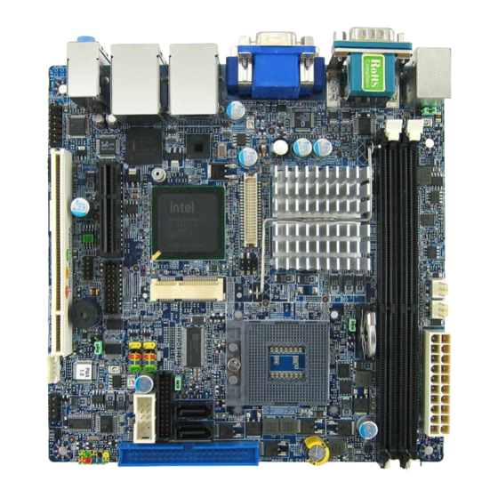
Page 10: Motherboard Layout
Product Overview Motherboard Layout MX965GME Mini ITX Motherboard... -
Page 11: Chapter 2 Hardware Setup
Hardware Setup Chapter 2 Hardware Setup This chapter provides you with the information about hardware setup procedures. While doing the installation, be careful in holding the components and follow the installation procedures. For some components, if you install in the wrong orientation, the components will not work properly. -
Page 12: Quick Components Guide
Quick Components Guide JAUD2 JAMP1 DIMM1, 2 PCI 1 JLVDS1 PCIE4 JTV1 JSPI2 CON1 CPU FAN SYS FAN JBAT1 CPU SOCKET F_USB1, 2 ATX POWER JCF_SEL1 JLPT1 COM2 SATA1, 2 JCASE1 JFP1 IDE1 CF1 (BOTTOM SIDE) MX965GME Mini ITX Motherboard... -
Page 13: Cpu (Central Processing Unit)
Hardware Setup CPU (Central Processing Unit) ® The mainboard supports Intel Core 2 Duo/Pentium Dual-Core/Celeron ® ® processors in Socket P. When you are installing the CPU, make sure the CPU has a heat sink and a cooling fan attached on the top to prevent overheating. If you do not have the heat sink and cooling fan, contact your dealer to purchase and install them before turning on the computer. - Page 14 MX965GME CPU & Cooler Installation for Socket P 1. Lo cate th e C PU s ock et on t h e mainboard. 2. Place the CPU on top of the socket. Make sure to align the gold arrow on the CPU with the arrow key on the socket.
- Page 15 Hardware Setup 5. Flip over the mainboard and locate the position of the CPU socket. 6. Install the backplate to the back of the CPU socket with holes aligned. CPU cooler backplate 7. The heatsink paste helps to enhance heat dissipation of the CPU. Before installing the cooler set (fan &...
-
Page 16: Memory
MX965GME Memory The DIMM slots are intended for system memory modules. DDR2 240-pin, 1.8V 64x2=128 pin 56x2=112 pin Installing DDR2 Modules 1. The memory module has only one notch on the center and will only fit in the right orientation. -
Page 17: Power Supply
Hardware Setup Power Supply ATX 20-Pin System Power Connector: ATX1 This connector allows you to connect to an ATX power supply. To connect to the ATX power supply, make sure the plug of the power supply is inserted in the proper orientation and the pins are aligned. -
Page 18: Back Panel
MX965GME Back Panel PS2 MS COM1 RGB VGA LAN2 LAN1 LINE-IN LINE-OUT PS2 KB HDMI DVI USB2 USB1 Mouse/Keyboard ® ® The standard PS/2 mouse/keyboard DIN connector is for a PS/2 mouse/keyboard. Serial Port The serial port is a 16550A high speed communications port that sends/ receives 16 bytes FIFOs. - Page 19 Hardware Setup Audio Ports These audio connectors are used for audio devices. You can differentiate the color of the audio jacks for different audio sound effects. Line-In (Blue) - Line In / Side-Surround Out in 7.1 channel mode, is used for extern al CD player, tap epl ayer or oth er aud io devices.
-
Page 20: Connector
MX965GME Connector Chassis Intrusion Connector: JCASE1 This connector connects to the chassis intrusion switch cable. If the chassis is opened, the chassis intrusion mechanism will be activated. The system will record this status and show a warning message on the screen. To clear the warning, you must enter the BIOS utility and clear the record. - Page 21 Hardware Setup Digital IO Connector: J4 The J4 is designed to connect the General-Purpose Input/Output (GPIO) peripheral module. Pin Definition SIGNAL SIGNAL VCC3 VCC5 N_GPIO10 N_GPIO20 N_GPIO11 N_GPIO21 N_GPIO12 N_GPIO22 N_GPIO13 N_GPIO23 N_GPIO14 N_GPIO24 N_GPIO15 N_GPIO25 N_GPIO16 N_GPIO26 N_GPIO17 N_GPIO27 Serial ATA II Connector: SATA1, SATA2 This connector is a high-speed Serial ATA II interface port.
- Page 22 MX965GME Audio Amplifier Connector: JAMP1 The JAMP1 is used to connect audio amplifiers to enhance audio performance. JAMP1 SIGNAL AMP_L- AMP_L+ AMP_R- AMP_R+ Front Audio Connector: JAUD2 The JAUD2 is used to connect audio to front panel. Signal Name Signal Name...
- Page 23 Hardware Setup Fan Power Connectors: CPUFAN1, SYSFAN1 The fan power connectors support system cooling fan with +12V. When connecting the wire to the connectors, always note that the red wire is the positive and should be connected to the +12V; the black wire is Ground and should be connected to GND. If the mainboard has a System Hardware Monitor chipset on-board, you must use a specially designed fan with speed sensor to take advantage of the CPU fan control.
- Page 24 MX965GME TV-Out Connector: JTV1 This connector is for you to attach an optional TV-Out bracket that offers two types of TV-Out connectors: S-Video and RCA Composite connectors. Select the appropri- ate one to connect the standard television or the HDTV (High-Definition TeleVision).
- Page 25 Hardware Setup LVDS Flat Panel Connector: JLVDS1 The LVDS (Low Voltage Differential Signal) connector provides a digital interface typically used with flat panels. JLVDS1 LVDS Connector (JLVDS1) Signal Signal VDD_SAFE3 VDD_SAFE3 VDD_SAFE5 VDD_SAFE5 DDC_DATA DDC_CLK LA_DATA0 LA_DATA1 LA_DATA0# LA_DATA1# LA_DATA2 LA_DATA3 LA_DATA2# LA_DATA3#...
- Page 26 MX965GME Front USB Connector: F_USB1, F_USB2 ® This connector, compliant with Intel I/O Connectivity Design Guide, is ideal for con- necting high-speed USB interface peripherals such as USB HDD, digital cameras, MP3 players, printers, modems and the like. Pin Definition...
- Page 27 Hardware Setup Serial Port Connector: COM 2 This connector is a 16550A high speed communications port that sends/receives 16 bytes FIFOs. You can attach a serial device to it through the optional serial port bracket. Pin Definition SIGNAL DESCRIPTION Data Carry Detect Serial In or Receive Data SOUT Serial Out or Transmit Data...
-
Page 28: Jumper
MX965GME Jumper Front Panel LAN LED: J8 Provide LAN Status to the front panel. Pin Definition Description Description LAN1_LED LAN2_LED LAN1_LED_1 LAN2_LED_1 LAN1_LED LAN2_LED LAN1_LED_11 LAN2_LED_11 COM Port Power Jumpers: J5, J6 These jumpers specify the operation voltage of the onboard serial ports. -
Page 29: Slot
Hardware Setup Slot PCI (Peripheral Component Interconnect) Express Slot The PCI Express x 4 slot supports PCI Express interface expansion card up to 2.0 GB/s transfer rate. (Note: Must use a right angle PCIE x4 riser card when using this slot.) The CON1 is Mini PCI-E connector for wireless LAN, TV tuner, and Robson NAND Flash. - Page 30 MX965GME CompactFlash Card Slot: CF1 This CompactFlash slot shares one channel of the IDE controller. You can install one CompactFlash typeI / type II device. CF Mode Selecting Jumper: JCF_SEL1 This jumper is used to select Master/ Slave mode of the CF device.
-
Page 31: Chapter 3 Bios Setup
BIOS Setup Chapter 3 BIOS Setup This chapter provides information on the BIOS Setup program and allows you to configure the system for optimum use. You may need to run the Setup program when: An error message appears on the screen during the system booting up, and requests you to run SETUP. -
Page 32: Entering Setup
2. Upon boot-up, the 1st line appearing after the memory count is the BIOS version. It is usually in the format: MX965GME #70551 BIOS V1.0 where: 1st word refers to model name. 2nd word refers to the model number. -
Page 33: Control Keys
BIOS Setup Control Keys <↑> Move to the previous item <↓> Move to the next item <←> Move to the item in the left hand <→> Move to the item in the right hand <Enter> Select the item Jumps to the Exit menu or returns to the main menu from a <Esc>... -
Page 34: The Menu Bar
MX965GME The Menu Bar Main Use this menu for basic system configurations, such as time, date etc. Advanced Use this menu to set up the items of special enhanced features. Boot Use this menu to specify the priority of boot devices. -
Page 35: Main
BIOS Setup Main AMI BIOS, Processor, System Memory These items show the firmware and hardware specifications of your system. Read only. System Time The time format is <Hour> <Minute> <Second>. System Date The date format is <Day>, <Month> <Date> <Year>. -
Page 36: Advanced
MX965GME Advanced CPU Configuration These items show the advanced specifications of your CPU. Read only. - Page 37 BIOS Setup IDE Configuration ATA/IDE Configuration This setting specifies the modes of the PATA & SATA ports. Configure SATA as s This setting specifies the function of the on-chip SATA controller.
- Page 38 MX965GME Primary/Secondary/Third/Fourth IDE Master/Slave [Type] Press PgUp/<+> or PgDn/<-> to select [Manual], [None] or [Auto] type. Note that the specifications of your drive must match with the drive table. The hard disk will not work properly if you enter improper information for this category.
- Page 39 BIOS Setup Super IO Configuration Serial Port 1 / 2 Address Select an address and a corresponding interrupt for the serial port 1/2. Parallel Port Address This setting specifies the I/O port address and IRQ of the onboard parallel port. Chassis Intrusion The field enables or disables the feature of recording the chassis intrusion status and issuing a warning message if the chassis is once opened.
- Page 40 MX965GME Hardware Health Configuration System 1 / 2 Temperature, CPU Temperature, CPUFAN Speed, Vcore, AVCC, 3VCC, +12V, 5V, VSB, VBAT These items display the current status of all of the monitored hardware de- vices/components such as CPU voltage, temperatures and all fans’ speeds.
- Page 41 BIOS Setup ACPI Configuration Suspend Mode This item specifies the power saving modes for ACPI function. If your operating system supports ACPI, you can choose to enter the Standby mode in S1 (POS) or S3 (STR) fashion through the setting of this field. Options are: [S1 (POS)] The S1 sleep mode is a low power state.
- Page 42 MX965GME APM Configuration Power M anagement/APM Setting to [Enabled] will activate an Advanced Power Management (APM) de- vice to enhance Max Saving mode and stop CPU internal clock. Power Button Mode This setting controls the operation of the power button.
- Page 43 BIOS Setup Intel Robson Configuration Intel Robson Robson is the code name for a new Intel platform technology that uses non- volatile memory (Flash memory) to increase system responsiveness, make multi-tasking faster, and extend battery life. Intel Robson technology is poised to eliminate many of the bottlenecks associated with HDD latency.
- Page 44 MX965GME Remote Access Configuration Remote Access This field allows you to Enabled or Disabled Remote Access for console redirection via serial ports. Set the desired port and setting in each field. 3-14...
- Page 45 BIOS Setup Trusted Computing TCG/TPM Support This setting controls the Trusted Platform Module (TPM) designed by the Trusted Computing Group (TCG). TPMs are special-purpose integrated circuits (ICs) built into a variety of platforms to enable strong user authentication and machine attestation—essential to prevent inappropriate access to confidential and sen- sitive information and to protect against compromised networks.
- Page 46 MX965GME USB Configuration Legacy USB Support Set to [Enabled] if you need to use any USB 1.1/2.0 device in the operating system that does not support or have any USB 1.1/2.0 driver installed, such as DOS and SCO Unix. USB 2.0 Controller Mode This setting specifies the operation mode of the onboard USB 2.0 controller.
-
Page 47: Boot
BIOS Setup Boot Boot Settings Configuration 3-17... - Page 48 MX965GME Quick Boot Enabling this setting will cause the BIOS power-on self test routine to skip some of its tests during bootup for faster system boot. Quiet Boot This BIOS feature determines if the BIOS should hide the normal POST mes- sages with the motherboard or system manufacturer's full-screen logo.
- Page 49 BIOS Setup ture" Interrupt 19. Therefore, you will not be able to boot operating systems from any bootable disks attached to these host adaptors. Nor will you be able to gain access to their ROM setup utilities. Flash Write Protection Select [Enabled] if you need to program data into the flash chip.
- Page 50 MX965GME Removable Drives 1st Drive This setting allows users to set the priority of the removable devices. First press <Enter> to enter the sub-menu. Then you may use the arrow keys ( ↑↓ ) to select the desired device, then press <+>, <-> or <PageUp>, <PageDown>...
-
Page 51: Security
BIOS Setup Security Supervisor Password / Change Supervisor Password Supervisor Password controls access to the BIOS Setup utility. These settings allow you to set or change the supervisor password. User Password / Change User Password User Password controls access to the system at boot. These settings allow you to set or change the user password. -
Page 52: Chipset
MX965GME Chipset 3-22... - Page 53 BIOS Setup North Bridge Configuration Boot Graphics Adapter Priority This item specifies which VGA card is your primary graphics adapter. Internal Graphics Mode Select The field specifies the size of system memory allocated for video memory. PEG Port This setting allows you to select whether to use the onchip graphics processor or the PCI Express card.
- Page 54 MX965GME Video Function Configuration DVMT Mode Select Intel's Dynamic Video Memory Technology (DVMT) allows the system to dy- namically allocate memory resources according to the demands of the sys- tem at any point in time. The key idea in DVMT is to improve the efficiency of the memory allocated to either system or graphics processor.
- Page 55 BIOS Setup South Bridge Configuration USB Functions This setting specifies the function of the onboard USB controller. USB 2.0 Controller Set to [Enabled] if you need to use any USB 2.0 device in the operating system that does not support or have any USB 2.0 driver installed, such as DOS and SCO Unix.
-
Page 56: Exit
MX965GME Exit Save Changes and Exit Save changes to CMOS and exit the Setup Utility. Discard Changes and Exit Abandon all changes and exit the Setup Utility. Discard Changes Abandon all changes and continue with the Setup Utility. Load Optimal Defaults Use this menu to load the default values set by the mainboard manufacturer specifi- cally for optimal performance of the mainboard.
Need help?
Do you have a question about the MX965GME and is the answer not in the manual?
Questions and answers