Table of Contents
Advertisement
Quick Links
Advertisement
Table of Contents

Subscribe to Our Youtube Channel
Related Manuals for BCM MX67QM


Summary of Contents for BCM MX67QM
- Page 1 User’s Manual MX67QM Industrial Mini ITX Motherboard WWW.BCMCOM.COM...
-
Page 2: Trademarks
Preface Copyright Notice The material in this document is the intellectual property of BCM Advanced Research. We take every care in the preparation of this document, but no guarantee is given as to the correctness of its contents. Our products are under continual improvement and we reserve the right to make changes without notice. -
Page 3: Safety Instructions
MX67QM Safety Instructions ■ Always read the safety instructions carefully. ■ Keep this User’s Manual for future reference. ■ Keep this equipment away from humidity. ■ Lay this equipment on a reliable flat surface before setting it up. ■ The openings on the enclosure are for air convection hence protects the equipment from overheating. -
Page 4: Ce Conformity
■ Preface CE Conformity Hereby, BCM Advanced Research declares that this device is in compliance with the essential safety requirements and other relevant provisions set out in the European Directive. FCC-B Radio Frequency Interference Statement This equipment has been tested and found to comply with the limits for a Class B digital device, pursuant to Part 15 of the FCC Rules. -
Page 5: Weee Statement
BCM will comply with the product take back requirements at the end of life of BCM-branded products that are sold into the EU. You can return these products to local collection points. - Page 6 BCM će poštovati zahtev o preuzimanju ovakvih proizvoda kojima je istekao vek trajanja, koji imaju BCM oznaku i koji su prodati u EU. Ove proiz- vode možete vratiti na lokalnim mestima za prikupljanje.
- Page 7 BCM si adeguerà a tale Direttiva ritirando tutti i prodotti marchiati BCM che sono stati venduti all’interno dell’Unione Europea alla fine del loro ciclo di vita.
-
Page 8: Table Of Contents
■ Preface CONTENTS Copyright Notice ................. ii Trademarks ..................ii Revision History .................. ii Safety Instructions ................iii CE Conformity ..................iv FCC-B Radio Frequency Interference Statement ......iv WEEE Statement ................v Chapter 1 Overview ������������������������������������������������������������������������������� 1-1 Mainboard Specifications ..............1-2 Mainboard Layout ................ -
Page 9: Chapter 1 Overview
Chapter 1 Overview The MX67QM is an Intel® QM67 Mini ITX Motherboard which supports the 2nd generation Intel® Core™ i7, i5, i3 Mobile processors providing advanced computing and graphics performance for gaming, POS, digital signage and server market segment Based on the innovative Intel Cougar Point chipset for opti- ®... - Page 10 ■ Overview MX67QM Specifications ■ Mobile Intel Core i3/ i5/ i7/ Celeron/ Pentium proces- sor (below 45 Watt) in socket PGA989 ■ North Bridge: integrated with CPU Chipset ■ South Bridge: Intel Cougar Point chipset ■ 2 DDR3 1066/1333/1600 SO-DIMM slots Memory ■...
- Page 11 MX67QM ■ 2 x USB 2.0 pinheaders (4 ports) Onboard I/O ■ 1 x Amplifier pinheader Headers ■ 4 x COM port connectors ■ 1 x GPIO pinheader ■ 1 x LVDS connector ■ 1 x Front audio pinheader ■ 1 x Chassis intrusion pinheader ■...
-
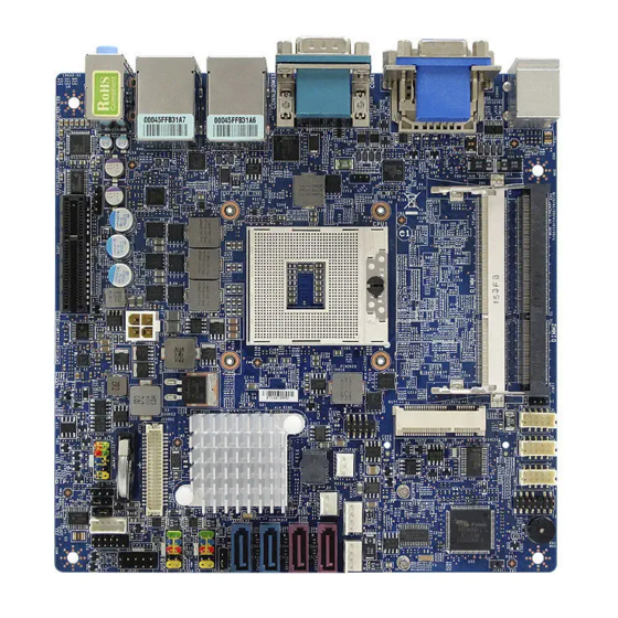
Page 12: Mainboard Layout
■ Overview Mainboard Layout Amplifier Pinheader COM Power Jumper PCIe Slot Power Connector DIMM Slot GPIO Pinheader Chassis Intrusion Pinheader Fan Power LVDS Inverter Connector Connector LVDS Port 80 Connector Pinheader Front Panel LVDS Power Pinheader Power Jumper Connector S/PDIF COM Power Serial Port Connector Pinheader... -
Page 13: Chapter 2 Hardware Setup
Chapter 2 Hardware Setup This chapter provides you with the information on mainboard hard- ware configurations. Incorrect setting of jumpers and connectors may damage your mainboard. Please pay special attention not to connect these headers in wrong direction. DO NOT adjust any jumper while the mainboard is powered on. -
Page 14: Quick Components Guide
■ Hardware Setup Quick Components Guide Amplifier Pinheader, COM Power Jumper, p.2-10 p.2-17 PCIe Slot, p.2-18 Power Connector, p.2-5 Slot, p.2-4 DIMM GPIO Pinheader, p.2-11 Chassis Intrusion Pinheader, p.2-9 Fan Power LVDS Inverter Connector, Connector, p.2-14 p.2-10 LVDS Port 80 Connector, Pinheader p.2-5... -
Page 15: Cpu
MX67QM ▶ Installing the CPU Important • On the upper end of the CPU socket is a socket actuator in the form of a slotted screw head. Make sure that you open or close the socket with a flathead screwdriver before and after installing the CPU. -
Page 16: Memory
■ Hardware Setup Memory ▶ Installing Memory Modules Locate the SO-DIMM slot. Align the notch on the DIMM with the key on the slot and insert the DIMM into the slot. Push the DIMM gently downwards until the slot levers click and lock the DIMM in place. -
Page 17: Power Supply
MX67QM Power Supply ATX Power Connector: ATX1 This connector provides power to the system. DC Power Connector: JPWR1 This connector provides 12V DC power input. -
Page 18: Back Panel I/O
■ Hardware Setup Back Panel I/O Serial Port LAN Jack LAN Jack Line-In Jack Mouse Port VGA Port Keyboard DVI-D Port HDMI Port USB 2.0 USB 3.0 Line-Out Jack Port Port Port Mic-In Jack ▶ Mouse/Keyboard Port The standard PS/2 mouse/keyboard DIN connector is for a PS/2 mouse/ keyboard. - Page 19 MX67QM ▶ RS-232/422/485 Serial Port Connector (Optional) The serial port is a 16550A high speed communications port that sends/ receives 16 bytes FIFOs. You can attach a serial mouse or other serial devices directly to the connector. RS-232 SIGNAL DESCRIPTION...
- Page 20 ■ Hardware Setup ▶ HDMI Port The High-Definition Multimedia Interface (HDMI) is an all-digital audio/video interface capable of transmitting uncompressed streams. HDMI supports all TV format, including standard, enhanced, or high-definition video, plus multi-channel digital audio on a single cable. ▶...
-
Page 21: Connector
MX67QM Connector Chassis Intrusion Pinheader: JCASE1 This connector is provided to connect the chassis intrusion switch cable. If the chassis is opened, the chassis intrusion mechanism will be activated. The system will record this status and show a warning message on the screen. - Page 22 ■ Hardware Setup Audio Amplifier Pinheader: JAMP1 The JAMP1 is used to connect audio amplifiers to enhance audio perfor- mance. Fan Power Connector: CPUFAN1, SYSFAN1 The fan power connector supports system cooling fan with +12V. When connecting the wire to the connectors, always note that the red wire is the positive and should be connected to the +12V;...
- Page 23 MX67QM GPIO Pinheader: JGPIO1 This connector is provided for the General-Purpose Input/Output (GPIO) peripheral module. Front Panel Pinheader: JFP1 This front panel connector is provided for electrical connection to the front panel switches & LEDs and is compliant with Intel Front Panel I/O Con- nectivity Design Guide.
- Page 24 ■ Hardware Setup Front USB Pinheader: JUSB1, JUSB2 This connector, compliant with Intel I/O Connectivity Design Guide, is ideal for connecting high-speed USB interface peripherals such as USB HDD, digital cameras, MP3 players, printers, modems and the like. USB 2.0 Bracket (Optional) Important Note that the pins of VCC and GND must be connected correctly to avoid Important...
- Page 25 MX67QM Serial Port Connector: COM2, COM3, COM4, COM5 This connector is a 16550A high speed communications port that sends/ receives 16 bytes FIFOs. You can attach a serial device to it through an optional serial port bracket. SIGNAL DESCRIPTION Data Carrier Detect...
- Page 26 ■ Hardware Setup LVDS Inverter Connector: JINV1 The connector is provided for LCD backlight options. LVDS Connector: JLVDS1 The LVDS (Low Voltage Differential Signal) connector provides a digital in- terface typically used with flat panels. After connecting an LVDS interface flat panel to the JLVDS1, be sure to check the panel datasheet and set the JVDD1 jumper to proper power voltage.
- Page 27 MX67QM S/PDIF Pinheader: JSPDI1 This connector is used to connect S/PDIF (Sony & Philips Digital Intercon- nect Format) interface for digital audio transmission. Front Audio Pinheader: JAUD1 This connector allows you to connect the front panel audio and is compliant with Intel Front Panel I/O Connectivity Design Guide.
-
Page 28: Jumper
■ Hardware Setup Jumper Clear CMOS Jumper: JCMOS1 There is a CMOS RAM onboard that has a power supply from an external battery to keep the data of system configuration. With the CMOS RAM, the system can automatically boot OS every time it is turned on. If you want to clear the system configuration, set the jumper to clear data. - Page 29 MX67QM AT/ATX Select Jumper: JAT1 This jumper allows users to select between AT and ATX power. JAT1 AT Power ATX Power COM Port Power Jumper: J1, JCMV2 These jumpers specify the operation voltage of the onboard serial ports. +12V (for COM1)
-
Page 30: Slot
■ Hardware Setup Slot Mini PCI-E (Peripheral Component Interconnect Ex- press) Slot The Mini PCI-E slot is provided for wireless LAN card, TV tuner card, and Robson NAND Flash card . PCI-E (Peripheral Component Interconnect Express) Slot The PCIE slot supports the PCIE interface expansion card. CompactFlash Socket This socket supports CompactFlash cards. -
Page 31: Chapter 3 Bios Setup
Chapter 3 BIOS Setup This chapter provides information on the BIOS Setup program and allows you to configure the system for optimum use. You may need to run the Setup program when: ■ An error message appears on the screen during the sys- tem booting up, and requests you to run SETUP. -
Page 32: Entering Setup
■ BIOS Setup Entering Setup Power on the computer and the system will start POST (Power On Self Test) process. When the message below appears on the screen, press <DEL> key to enter Setup. Press DEL to enter SETUP If the message disappears before you respond and you still wish to enter Setup, restart the system by turning it OFF and On or pressing the RESET button. -
Page 33: Control Keys
MX67QM Control Keys ← → Select Screen ↑ ↓ Select Item Enter Select Change Option General Help Previous Values Optimized Defaults Save & Exit Exit Getting Help After entering the Setup menu, the first menu you will see is the Main Menu. -
Page 34: The Menu Bar
■ BIOS Setup The Menu Bar ▶ Main Use this menu for basic system configurations, such as time, date, etc. ▶ Advanced Use this menu to set up the items of special enhanced features. ▶ Boot Use this menu to specify the priority of boot devices. ▶... -
Page 35: Main
MX67QM Main ▶ System Date This setting allows you to set the system date. The date format is <Day>, <Month> <Date> <Year>. ▶ System Time This setting allows you to set the system time. The time format is <Hour> <Minute> <Second>. - Page 36 ■ BIOS Setup [LBA/Large Enabling LBA causes Logical Block Address- Mode] ing to be used in place of Cylinders, Heads and Sectors [Block Any selection except Disabled determines the (Multi-Sector number of sectors transferred per block Transfer)] [PIO Mode] Indicates the type of PIO (Programmed Input/Output) [DMA Mode] Indicates the type of Ultra DMA...
-
Page 37: Advanced
MX67QM Advanced ▶ Quiet Boot This BIOS feature determines if the BIOS should hide the normal POST messages with the motherboard or system manufacturer’s full-screen logo. When it is enabled, the BIOS will display the full-screen logo during the boot-up sequence, hiding normal POST messages. - Page 38 ■ BIOS Setup ▶ Option ROM Messages This item is used to determine the display mode when an optional ROM is initialized during POST. When set to [Force BIOS], the display mode used by AMI BIOS is used. Select [Keep Current] if you want to use the display mode of optional ROM.
- Page 39 MX67QM ▶ Launch Intel 82579 OpROM, Launch Intel 82574 OpROM, Launch JMB368 OpROM This setting enables/disables the initialization of the onboard LAN Boot ROM during bootup. Selecting [Disabled] will speed up the boot pro- cess. ▶ CPU Configuration ▶ Hyper Threading The processor uses Hyper-Threading technology to increase transac- tion rates and reduces end-user response times.
- Page 40 ■ BIOS Setup ▶ Execute Disable Bit Intel’s Execute Disable Bit functionality can prevent certain classes of mali- cious “buffer overflow” attacks when combined with a supporting operating system. This functionality allows the processor to classify areas in memory by where application code can execute and where it cannot. When a mali- cious worm attempts to insert code in the buffer, the processor disables code execution, preventing damage or worm propagation.
- Page 41 MX67QM ▶ Super IO Configuration ▶ Serial Port 1/ 2/ 3/ 4/ 5 This setting enables/disables the specified serial port. ▶ Change Settings This setting is used to change the address & IRQ settings of the specified serial port. ▶ Mode Select Select an operation mode for the serial port 1.
- Page 42 ■ BIOS Setup ▶ H/W Monitor These items display the current status of all monitored hardware devices/ components such as voltages, temperatures and all fans’ speeds. 3-12...
- Page 43 MX67QM ▶ Smart Fan Configuration ▶ Smart FAN1 / FAN2 Function This setting enables/disables the Smart Fan function. Smart Fan is an excellent feature which will adjust the CPU/system fan speed automatically depending on the current CPU/system temperature, avoiding the overheating to damage your system.
- Page 44 ■ BIOS Setup ▶ GPIO Group Configuration ▶ GP 01/ 02/ 03/ 04/ 05/ 06/ 07/ 08 This setting controls the operation mode of the specified GPIO. 3-14...
-
Page 45: Boot
MX67QM Boot ▶ Boot Option #1 / #2 / #3 / #4 This setting allows users to set the sequence of boot devices where BIOS attempts to load the disk operating system. ▶ CD/DVD ROM Drive BBS Priorities, Hard Drive BBS Priorities This setting allows users to set the priority of the specified devices. -
Page 46: Security
■ BIOS Setup Security ▶ Administrator Password Administrator Password controls access to the BIOS Setup utility. ▶ User Password User Password controls access to the system at boot and to the BIOS Setup utility. ▶ Chassis Intrusion The field enables or disables the feature of recording the chassis intrusion status and issuing a warning message if the chassis is once opened. - Page 47 MX67QM ▶ Trusted Computing ▶ TPM Support This setting controls the Trusted Platform Module (TPM) designed by the Trusted Computing Group (TCG). TPMs are special-purpose inte- grated circuits (ICs) built into a variety of platforms to enable strong user authentication and machine attestation - essential to prevent inap- propriate access to confidential and sensitive information and to protect against compromised networks.
- Page 48 ■ BIOS Setup ▶ Intel TXT(LT) Configuration ▶ Secure Mode Extensions (SMX) This setting enables/disables the Secure Mode Extensions. ▶ Intel TXT(LT) Support Intel TXT (Trusted Execution Technology) can only be enabled/disabled if SMX is enabled. VT and VT-d support must also be enabled prior to TXT.
- Page 49 MX67QM ▶ PCH-FW Configuration ▶ ME FW Version, ME Firmware Mode/ Type/ Sku These settings show the firmware information of the Intel ME (Manage- ment Engine). ▶ Firmware Update Configuration Press [Enter] to view the firmware update configuration. 3-19...
- Page 50 ■ BIOS Setup ▶ AMT Configuration Intel Active Management Technology (AMT) is hardware-based technology for remotely managing and securing PCs out-of-band. 3-20...
- Page 51 MX67QM ▶ Serial Port Console Redirection ▶ Console Redirection Console Redirection operates in host systems that do not have a moni- tor and keyboard attached. This setting enables/disables the opera- tion of console redirection. When set to [Enabled], BIOS redirects and sends all contents that should be displayed on the screen to the serial COM port for display on the terminal screen.
-
Page 52: Chipset
■ BIOS Setup Chipset ▶ Primary Display This setting specifies which graphics device will be used as the primary display. ▶ Internal Graphics This setting specifies the size of system memory allocated for video mem- ory. ▶ GTT Size This setting specifies the GTT size. ▶... - Page 53 MX67QM ▶ Primary Boot Display Use the field to select the type of device you want to use as the boot display of the system. ▶ LCD Panel Type, Panel Scaling, Panel Color Depth This setting allows you to set your preferences for the boot display device.
-
Page 54: Power
■ BIOS Setup Power ▶ ACPI Sleep State This item specifies the power saving modes for ACPI function. If your oper- ating system supports ACPI, you can choose to enter the Standby mode in S1 (POS) or S3 (STR) fashion through the setting of this field. ▶... - Page 55 MX67QM ▶ Resume On 82579 LAN This field specifies whether the system will be awakened from power saving modes when activity or input signal of onboard LAN is detected. ▶ Resume On PCIE PME This field specifies whether the system will be awakened from power saving modes when activity or input signal of onboard PCIE PME is detected.
-
Page 56: Save & Exit
■ BIOS Setup Save & Exit ▶ Save Changes and Exit Save changes to CMOS and exit the Setup Utility. ▶ Discard Changes and Exit Abandon all changes and exit the Setup Utility. ▶ Save Changes and Reset Save changes to CMOS and reset the system. ▶...
Need help?
Do you have a question about the MX67QM and is the answer not in the manual?
Questions and answers