Table of Contents
Advertisement
Quick Links
Advertisement
Table of Contents

Related Manuals for BCM MX266


Summary of Contents for BCM MX266
- Page 1 Motherboard with VIA Eden Processor MX266 User’s Manual http://www.bcmcom.com...
- Page 2 CAUTION: References: This manual is created and written by BCM Technical Dept., but not limited, to the information from the MX266 External Production Specifications, and MX266 Specifications. If any comments, suggestions, or errors for this manual, please write an e-mail to support@bcmcom.com.
- Page 3 Compliance & Certificate & & ISO 9001 Certificate: This device was produced in our plant with advanced quality system certified by DNV QA Ltd. in according to ISO 9001. This Certificate is valid for: DESIGN & MANUFACTURE OF MOTHERBOARD AND PERSONAL COMPUTERS. CE Declaration: CE marking is a visible declaration by the manufacturer or his authorized representatives that the electrical equipment to which it relates satisfies all the provisions of the 1994...
-
Page 4: Easy Installation
Easy Installation Easy Installation Steps The following “Easy Installation” steps are for users accustomed to the assembly of a computer system. For those individuals requiring more specific information, please refer to the more detailed descriptions located within the latter chapters of this manual. Note: You must keep your power cable unplugged until the following installation steps are completed. -
Page 5: Table Of Contents
TABLE OF CONTENT USER’S NOTICE MANUAL REVISION INFORMATION COOLING SOLUTIONS CHAPTER 1 INTRODUCTION OF MX266 MOTHERBOARD 1-1 FEATURE OF MOTHERBOARD 1-2 SPECIFICATION 1-3 LAYOUT DIAGRAM 1-4 JUMPER & CONNECTOR SETTING CHAPTER 2 HARDWARE INSTALLATION 2-1 HARDWARE INSTALLATION STEPS 2-2 CHECKING MOTHERBOARD'S JUMPER SETTING... -
Page 6: User's Notice
REPRODUCED, TRANSMITTED OR TRANSLATED INTO ANY LANGUAGE IN ANY FORM OR BY ANY MEANS WITHOUT WRITTEN PERMISSION OF THE MANUFACTURER. THIS MANUAL CONTAINS ALL INFORMATION NECESSARY TO USE OF MX266 MOTHER- BOARD AND WE DO ASSURE THIS MANUAL CONTENT AS MANY INFORMATION AS POSSIBLE, BUT WE RESERVE RIGHT TO CHANGE, UPDATE ANYTIME WITHOUT PRIOR NOTICE. - Page 7 VIA Eden ESP Processor Family Advanced CoolStream Architecture The MX266 has been design with VIA Eden processor and CLE266 Chipset that incorporate with the low heat and high performance x86 processor The VIA Eden ESP10000 and ESP8000 employ VIA's advanced CoolStream™ architecture that is packed with new digital media performance features, including support for sixteen pipeline stages, SSE multimedia instructions, StepAhead™...
-
Page 8: Feature Of Motherboard
With integrated 8x AGP 2D/3D Graphics Accelerator which supports 128bit 2D/ 3D graphics engine, supports hardware motion compensation assist for software MPEG/DVD decode, makes this board a low cost and high performance solution. The MX266 also provide DFP support for those who wish to use of a digital display equip with LVDS TFT panel. -
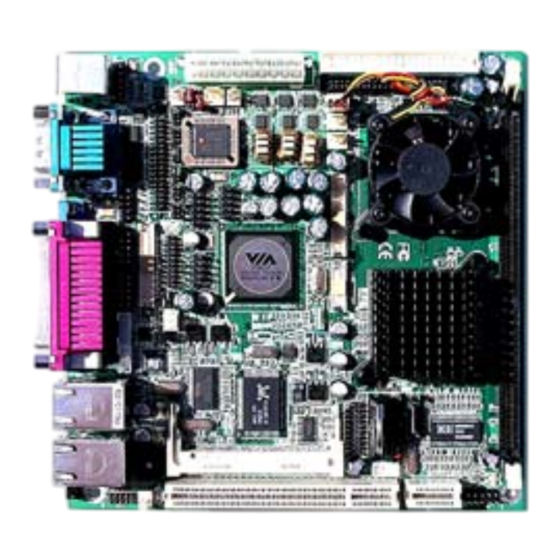
Page 9: Specification
1-2 Specification Spec Description ∗ Design Mini ITX form factor 6 layers PCB size: 6.69”(W) x 6.69”(D) (170 x 170 mm) ∗ Chipset VIA VT8623 North Bridge Chipset ∗ VIA VT8237 South Bridge Chipset ∗ CPU Socket Support VIA Eden ESP10000 (Nehemiah) processor 2x64K cache on 0.13 micron process EBGA processor. -
Page 10: System Diagram
1-3 System Diagram MX266 Mainboard Diagram... - Page 11 Jumper & Connector Ext. LAN LED IRDA Audio Header COM3/ 4 DFP LVDS Ext. PC SPK Connector Floppy Brightness Adjust PCI /Riser Slot USB 7/ 8 AT/ATX USB 5/ 6 Auxiliary Power Compact PCI Reserved ATX Power PCI /Riser Slot CPU Fan Header SATA 1 /2 Primary/ Secondary...
- Page 12 Jumpers Jumper Name Description Page Clear CMOS 3-pin Block Power Mode 3-pin Block CF MA/SL Select 3-pin Block COM2 P9 Select 6-pin Block COM2 Mode Select 6-pin Block COM2 Mode Select 6-pin Block COM2 Mode Select 6-pin Block COM3 P9 Select 6-pin Block COM4 P9 Select 6-pin Block...
-
Page 13: Chapter 2 Hardware Installation
Chapter 2 Hardware installation 2-1 Hardware installation Steps Before using your computer, you had better complete the following steps: 1. Check motherboard jumper setting 2. Install CPU and Fan 3. Install System Memory (DIMM) 4. Install Expansion cards 5. Connect IDE and Floppy cables, Front Panel /Back Panel cable 6. - Page 14 (2) COM Ports Settings COM3 / 4 Pin 9 Signal Select (JP9, JP8) MX266 COM3 / 4 pin 9 signal can be selected as +12V, +5V, or Ring by setting JP9 / JP8 / JP4. COM3 / COM4 / COM2 Select (JP9, JP8, JP4)
-
Page 15: Glossary
2-3 Install CPU 2-3-1 Glossary Chipset (or core logic) – A highly integrated circuits which control the interfaces between the system processor, RAM, I/O devises, and adapter cards. Processor slot/socket - the slot or socket used to mount the system processor on the motherboard. Slot (AGP, PCI, ISA, RAM) - the slots used to mount adapter cards and system RAM. - Page 16 2-3-2 About VIA Eden ESP 10000 This motherboard provides with a build onboard VIA Eden 1000MHz embedded system platform processor. The VIA Eden ESP architecture and companion chips provide a x86-base solution, a highly compatible, high performance, cost efficiency and low power solution for embedded system application, utilizes 0.13 micron EBGA package technology, value added from the advanced EBGA packaging includes remarkable compactness, cost efficiency and excellent characteristics.
-
Page 17: Install Memory
2-4 Install Memory This motherboard provides one 184-pin DIMM (DUAL INLINE MEMORY MODULES) sites for memory expansion available to maximum memory size of 1.0GB DDR SDRAM. • Support 128Mb, 256Mb, 512Mb technologies implemented as x8, x16 devices. • ECC, Non-ECC DIMMS. Valid Memory Configurations Bank 184-Pin DIMM... -
Page 18: Expansion Card
2-5 Expansion Cards Turn off your power when adding or removing expansion cards or other system WARNING! components. Failure to do so may cause severe damage to both your motherboard and expansion cards. 2-5-1 Procedure For Expansion Card Installation 1. Read the documentation for your expansion card and make any necessary hardware or software setting for your expansion card such as jumpers. -
Page 19: Interrupt Request Table For This Motherboard
2-5-3 Interrupt Request Table For This Motherboard Interrupt request are shared as shown the table below: INT A INT B INT C INT D INT E INT F INT G INT H √ Slot 1 √ Slot 2 √ Slot 3 √... -
Page 20: Connectors, Headers
2-6 Connectors, Headers 2-6-1 Connectors Power Connector (20-pin block): ATXPWR ATX Power Supply connector. This is a 20-pins connector that usually comes with ATX case. The ATX Power Supply allows to use soft power on with a momentary switch that connect from the front panel switch to 2-pins Power On jumper pole on the motherboard. - Page 21 Floppy drive Connector (34-pin block): FDD This connector supports the provided floppy drive ribbon cable. After connecting the single plug end to motherboard, connect the two plugs at other end to the floppy drives. Signal Signal DRVDEN0# DRVDEN1# INDEX# MOA# DSB# DSA# MOB#...
- Page 22 (10) Primary IDE Connector (40-pin block): IDE1 (CN10) This connector supports the provided IDE hard disk ribbon cable. After connecting the single plug end to motherboard, connect the two plugs at other end to your hard disk(s). If you install two hard disks, you must configure the second drive to Slave mode by setting its jumpers accordingly.
- Page 23 • For performance issues, we strongly suggest you don’t install a CD-ROM or DVD-ROM drive on the same IDE channel as a hard disk. Otherwise, the system performance on this channel may drop. (12) Serial ATA (CN2, CN4) This connector supports Serial ATA device. After connecting the single plug end to motherboard, connect the plug at other end to the SATA device.
-
Page 24: Headers
2-6-2 Headers Serial Port COM3/ 4 Header (9-pin) : COM3 (CN26), COM4 (CN27) COM3/ 4 Signal Signal Pin 1 Serial Port 3/ 4 COM3/4 Header *COM 2, COM3 and COM4 pin 9 signal can be select as ring in, +5V or +12V. Audio Header (9-pin): AUDIO (CN29) This header connects to Front Panel Line-out, MIC connector with cable. - Page 25 IDE Activity LED: IDE LED (CN1 1-3 This connector connects to the hard disk activity indicator light on the case. Reset switch lead: RESET (CN1 5-7) This 2-pin connector connects to the case-mounted reset switch for rebooting your computer without having to turn off your power switch. This is a preferred method of rebooting in order to prolong the lift of the system’s power supply.
- Page 26 (10) CD Audio-In Headers (4-pin): CD-IN (CN31) CDIN are the connectors for CD-Audio Input signal. Please connect it to CD-ROM CD- Audio output connector. CD Audio-In Header Signal CD-IN CD-R CD-L (11) LCD Panel and Inverter Header (40-pin): LVDS (CN28) LCD Panel Connector HIROSE DF-13-40DP-1.25V Signal...
- Page 27 (13) IrDA Connector (CN25) Signal IRRX IRTX (14) LPC (CN22) Signal Signal LAD0 LPCCLK LAD1 LAD2 LPCSIO LAD3 PCIRSTX LFRAME LDRQ LDRQ1 SMBCK SERIRQ SMBDT (15) Brightness Adjust (CN23) Signal J1 pin 4 Variation Resistor (Recommended: 4.7KΩ, >1/16W) (16) LAN LED Header (CN36) Signal Signal VCC3...
-
Page 28: Starting Up Your Computer
PSON# Warning: The MX266 is capable of use two type of power input, a standard ATX power supply or a single source 5V power supply, incase of using single 5V power source, all connector that provide 12V or 3.3V will no longer available (Example of 12V on PCI slot, LCD inverter and LCD panel connector etc.). - Page 29 1. After all connection is made, close your computer case cover. 2. Be sure all the switch are off, and check that the power supply input voltage is set to the local voltage, usually in-put voltage is 220V∼240V or 110V∼120V depending on your country’s voltage used.
-
Page 30: Chapter 3 Introducing Bios
Chapter 3 Introducing BIOS The BIOS is a program located on a Flash Memory on the motherboard. This program is a bridge between motherboard and the operating system. When you start the computer, the BIOS program gain control. The BIOS first operates a self-diagnostic test called POST (Power On Self Test) for all the necessary hardware, it detects the entire hardware device and configures the parameters of the hardware synchronization. -
Page 31: The Main Menu
3-3 The Main Menu Once you enter Award ® BIOS CMOS Setup Utility, the Main Menu (Figure 3-1) will appear on the screen. The Main Menu allows you to select from fourteen setup functions and two exit choices. Use arrow keys to select among the items and press <Enter> to accept or enter the sub- menu. - Page 32 This entry shows your PC health status. Frequency/Voltage Control Use this menu to specify your settings for frequency clock control. Load Optimized Defaults Use this menu to load the BIOS default values that are settings for optimal performances system operations. Load Standard Defaults Use this menu to load the BIOS default values that are factory settings for the stable performance system operation.
-
Page 33: Standard Cmos Features
3-4 Standard CMOS Features The items in Standard CMOS Setup Menu are divided into several categories. Each category includes no, one or more than one setup items. Use the arrow keys to highlight the item and then use the <PgUp> or <PgDn> keys to select the value you want in each item. Phoenix –... - Page 34 If you select Manual, related information is asked to be entered to the following items. Enter the information directly from the keyboard. This information should be provided in the documentation from your hard disk vendor or the system manufacturer. If the controller of HDD interface is SCSI, the selection shall be “None”. If the controller of HDD interface is CD-ROM, the selection shall be “None”...
-
Page 35: Advanced Bios Features
3-5 Advanced BIOS Features Phoenix – AwardBIOS CMOS Setup Utility Advanced BIOS Features Hard Disk Boot Priority [Press Enter] Virus Warning [Disabled] Item Help CPU Internal Cache [Enabled] CPU L2 Cache ECC Checking [Disabled] Quick Power On Self Test [Enabled] Menu Level >... - Page 36 CPU Internal Cache The default value is Enabled. Enabled (default) Enable cache Disabled Disable cache Note: The internal cache is built in the processor. External Cache Choose Enabled or Disabled. This option enables the Level 2 cache memory. CPU L2 Cache ECC Checking Choose Enabled or Disabled.
- Page 37 Sets a number of times to repeat a keystroke in a second when you hold the key down. The settings are: 6, 8, 10, 12, 15, 20, 24, and 30. Typematic Delay (Msec) Sets the delay time after the key is held down before is begins to repeat the keystroke. The settings are 250, 500, 750, and 1000.
-
Page 38: Advanced Chipset Features
3-6 Advanced Chipset Features The Advanced Chipset Features Setup option is used to change the values of the chipset registers. These registers control most of the system options in the computer. Phoenix – AwardBIOS CMOS Setup Utility Advanced Chipset Features ►... -
Page 39: Dram Clock/Driver Control Settings
VGA Share Memory Size In this item you can assign video memories size share from the system memories, available options are 16, 32, 64. Select Display Device Allow you to select type of display CRT, LCD, DVI, TV. TV_Type Allow you to select TV standard NTSC, PAL… TV_Connector Allow you to select type of TV connector SVideo, RGB, CVBS, SDTV…... -
Page 40: Dram Timing Settings
DRAM Timing When “By SPD” has been select, BIOS will read SDRAM module SPD information pre-define by memory module manufacture. SDRAM CAS Latency When synchronous DRAM is installed, the number of clock cycles of CAS latency depends on the DRAM timing. The settings are: 2T and 2.5T. Note: Change these settings only if you are familiar with the chipset. - Page 41 This item allows you to adjust the AGP driving force. Choose Manual to key in an AGP Driving Value in the next selection. This field is recommended to set in Auto to avoid any error in your system. AGP Driving Value This item allows you to adjust the AGP driving force.
-
Page 42: Integrated Peripherals
3-7 Integrated Peripherals Phoenix – AwardBIOS CMOS Setup Utility Integrated Peripherals ► VIA OnChip IDE Device [Press Enter] ► VIA OnChip PCI Device [Press Enter] Item Help ► Super IO Device [Press Enter] Init Display First [PCI Slot] V-Link Data 2X Support [Disabled] Menu Level >... -
Page 43: Via Onchip Ide Device Settings
3-7-1 VIA OnChip IDE Device Settings Phoenix – AwardBIOS CMOS Setup Utility VIA OnChip IDE Device OnChip SATA [Disabled] X SATA Mode RAID Item Help OnChip IDE Channel0 [Enabled] OnChip IDE Channel1 [Enabled] IDE Prefetch Mode [Enabled] Menu Level >> Primary Master [Auto] Primary Slave... -
Page 44: Via Onchip Pci Device Settings
master driver). If your hard drive and your system software both support Ultra DMA/33 and Ultra DMA/66, select Auto to enable BIOS support. The settings are: Auto, Disabled. IDE HDD Block Mode Block mode is also called block transfer, multiple commands, or multiple sectors read/write. If your IDE hard drive supports block mode (most new drives do), select Enabled for automatic detection of the optimal number of block read/writes per sector the drive can support. -
Page 45: Super Io Device Settings
This item allows you to enable/ disable the Onchip USB controller. Available option are All Enabled, All Disabled, USB Port 1 & 2, USB Port 1 & 2 & 3, USB Port 1 & 3, and USB Port 1 Only. OnChip EHCI Controller This item allows you to enable/ disable USB 2.0 function. - Page 46 Onboard Serial Port 2 This item allows you to select the serial port 2 I/O/ IRQ to be used. Onboard Parallel Port There is a built-in parallel port on the on-board Super I/O chipset that Provides Standard, ECP, and EPP features.
-
Page 47: Power Management Setup
3-8 Power Management Setup The Power Management Setup allows you to configure your system to most effectively save energy saving while operating in a manner consistent with your own style of computer use. CMOS Setup Utility – Copyright(C) 1984-2002 Award Software Power Management Setup ACPI Function [Enable]... - Page 48 Modem Use IRQ This determines the IRQ in which the MODEM can use. The settings are: 3, 4, 5, 7, 9, 10, 11, NA. Power Button Function Pressing the power button for more than 4 seconds forces the system to enter the Soft-Off state. The settings are: Delay 4 Sec, Instant-Off.
-
Page 49: Pnp/Pci Configuration Setup
3-9 PnP/PCI Configuration Setup Phoenix – AwardBIOS CMOS Setup Utility PnP/PCI Configurations PNP OS Installed [No] Reset Configuration Data [Disabled] Item Help Resources Controlled By [Auto(ESCD)] x IRQ Resources Press Enter Menu Level > PCI/VGA Palette Snoop [Disabled] Assign IRQ For VGA [Enabled] Assign IRQ For USB [Enabled]... -
Page 50: Pc Health Status
3-10 PC Health Status This section shows the Status of you CPU, Fan, Warning for overall system status. This is only available if there is Hardware Monitor onboard. Phoenix – AwardBIOS CMOS Setup Utility PC Health Status 35 ° C/ 95 ° F Current System Temp.1 Item Help 37 °... -
Page 51: Load Standard/Optimized Defaults
3-11 Frequency/Voltage Control This section is for setting CPU Frequency/Voltage Control. Phoenix – AwardBIOS CMOS Setup Uitility Frequency/ Voltage Control Auto Detect PCI CLK [Enabled] Spread Spectrum [Disabled] Item Help CPU Host/AGP/PCI Clock [Default] Menu Level > ↑↓→← Move Enter:Select +/-/PU/PD:Value F10:Save ESC:Exit F1:General Help F5:Previous Values F6:Optimized Defaults... -
Page 52: Set Supervisor/User Password
Security option. If the Security option is set to “System”, the password will be required both at boot and at entry to Setup. If set to “Setup”, prompting only occurs when trying to enter Setup. MX266 Motherboard I/O Mechanical Draw...
Need help?
Do you have a question about the MX266 and is the answer not in the manual?
Questions and answers