
Subscribe to Our Youtube Channel
Related Manuals for BCM MX610H


Summary of Contents for BCM MX610H
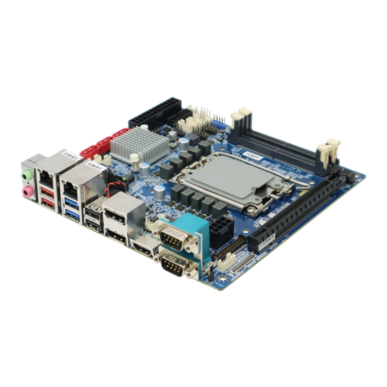
- Page 1 MX610H Intel® 12th Generation Core™ Processor Mini- ITX Motherboard With Intel® H610E Chipset User’s Manual Edition 1.0 – Oct, 2022...
- Page 2 Consult the dealer or an experienced radio/television technician for help. Notice BCM Advanced Research, ALL RIGHTS RESERVED. No part of this document may be reproduced, copied, translated, or transmitted in any form or by any means, electronic or mechanical, for any purpose, without the prior written permission of the original manufacturer.
- Page 3 Disclaimer BCM Advanced Research reserves the right to make changes, without notice, to any product, including circuits and/or software described or contained in this manual in order to improve design and/or performance. BCM Advanced Research assumes no responsibility or liability for the use of the described product(s),...
- Page 4 Our team is well trained and ready to give you the support you need to get the most from your BCM products. In fact, most problems reported are minor and are able to be easily solved over the phone.
- Page 5 Because of BCM high quality-control standards and rigorous testing, most of our customers never need to use our repair service. If any of BCM products is defective, it will be repaired or replaced at no charge during the warranty period. For out-of-warranty repairs, you will be billed according to the cost of replacement materials, service time, and freight.
- Page 6 This manual describes in detail the BCM MX610H Main board. We strongly recommend that you study this manual carefully before attempting to interface with MX610H or change the standard configurations. Whilst all the necessary information is available in this manual, we would recommend that unless you are confident, you contact your supplier for guidance.
-
Page 7: Table Of Contents
Contents Chapter 1: System Setup .................... 13 1.1 Welcome! ......................... 13 1.2 Packing Contents ....................13 1.3 Features ........................14 1.4 Before you proceed ....................14 1.5 Mainboard Overview ....................15 1.5.1 Placement Direction ................... 15 1.5.2 Mounting Holes ....................16 1.5.3 Mainboard Layout .................... - Page 8 1.10.8 PS/2 Port Connector: JKBMS1 ..............32 1.10.9 Front Panel Connectors: JFP1 ..............32 1.10.10 USB 3.2 Gen1 Connector: JUSB3 ............... 33 1.10.11 Digital I/O Connector: JGPIO1 ..............33 1.10.12 LVDS Inverter Connector: JINV1 ..............34 1.10.13 LVDS Connector: JLVDS1 ................34 1.10.14 eDP Connector: EDP1 ...................
- Page 9 3.3.7 PCI/ PCIE Device Configuration ................55 3.3.8 GPIO Group Configuration .................. 55 3.4 Chipset ........................56 3.5 Power ........................57 3.6 Security ........................58 3.6.1 Trusted Computing ....................59 3.6.2 PCH-FW Configuration ..................60 3.6.2.1 PTT Configuration .................... 60 3.6.3 Serial Port Console Redirection ................
- Page 10 Mainboard Specifications Model MX610H Processor Intel® Alder Lake-S Processor Up to 16 Cores 24 Threads Hybrid LGA1700 Supports Core i9, Core i7, Core i5, Core i3, Pentium, Celeron Chipset Intel ® H610E 2 x DDR5 SO-DIMM slots (262 pin) Memory...
- Page 11 Smart FAN 1 x PWM FAN for CPU 1 x PWM FAN for System Audio Realtek® ALC897 HD Audio Codec with Auto Jack Sensing 1 x Intel® I219-LM GbE LAN PHY 1 x Intel® i225-V 2.5GbE LAN BIOS AMI BIOS with 256Mb SPI ROM Others IO 8-Bit Digital IO (4 x GPI, 4 x GPO) SMBus...
- Page 12 2 x 2*3-Pin Headers provide selections of “Ring-In”, or “12V” or “5V” on COM1&2 COM Port Ring-In/ Power Select and COM3&COM4 ports AT/ATX Select 1 x 1*3-Pin Header Clear CMOS 1 x 1*3-Pin Header ME FW Enable/Disable Select 1 x 1*3-Pin Header LVDS Backlight Control Select 1 x 1*3-Pin Header eDP Backlight Power Select...
-
Page 13: Chapter 1: System Setup
This chapter describes the mainboard features and the new technologies it supports. 1.1 Welcome! The mainboard delivers a host of new features and latest technologies, making it another line of BCM long life mainboards! Before you start installing the mainboard and hardware devices on it, check the items in your package with the list below. -
Page 14: Features
1.3 Features MX610H block Diagram 1.4 Before you proceed Take note of the following precautions before you install mainboard components or change any mainboard settings. • Unplug the power cord from the wall socket before touching any component inside the system. -
Page 15: Mainboard Overview
that came with the component. • Before you install or remove any component, ensure that the ATX power supply is switched off or the power cord is detached from the power supply. Failure to do so may cause severe damage to the mainboard, peripherals, and/or component. 1.5 Mainboard Overview Before you install the mainboard, study the configuration of your chassis to ensure that the mainboard fits into it. -
Page 16: Mounting Holes
1.5.2 Mounting Holes Place the screws into the mounting holes indicated by the red circles to secure the mainboard to the chassis. Do not over-tighten the screws! Doing so may damage the mainboard. -
Page 17: Mainboard Layout
1.5.3 Mainboard Layout • Back Panel:... -
Page 18: Layout Content List
1.5.4 Layout Content List 1.5.4.1 Slots Label Function Note Page DIMM1 262-pin DIMM slot 1 If there is only one memory module being installed in the system, install it on this slot first. DIMM2 262-pin DIMM slot 2 SLOT1 PCI express x16 slot M2_E1 2230 M.2 slot E Key M2_M1... -
Page 19: Back Panel Connectors
JSATA1/2/3 Serial ATA Connectors 7-pin CPUFAN1 CPU Fan Connector 1 x 4 wafer, pitch 2.54mm SYSFAN1 System Fan Connector 1 x 4 wafer, pitch 2.54mm JI2C1 1 x 4 wafer, pitch 2.0mm JSMB1 SMBus 1 x 4 wafer, pitch 2.0mm JFP1 System Panel Connector 2 x 5 header, pitch 2.54mm... -
Page 20: Mating Connectors List
1.5.4.5 Mating Connectors list Connector/Header Location Mating P/N Connector/Header P/N HORNG TONG Amplified Speakers JAMP1 JST PHR-4 or equivalent WF04N22DJF006 HORNG TONG Backlight JINV1 JST PHR-5 or equivalent WF05N22WJQ006 JST PHDR-10VS or HORNG TONG COM Port JCOM3; JCOM4 equivalent WF10N63WAA210 EDP1 I-PEX 20453-040T-11 HIROSE KN38A-40S-0.5H(800) -
Page 21: Cpu (Central Processing Unit)
1.6 CPU (Central Processing Unit) When installing the CPU, make sure that you install a cooler to prevent overheating. If you do not have a CPU cooler, consult your vendor before turning on the computer. Overheating Overheating may seriously damage the CPU and system. Always make sure the cooling fan can work properly to protect the CPU from overheating. -
Page 22: Installing Cpu
1.6.1 Installing CPU... -
Page 24: Installing Dimm
1.7 Installing DIMM 1.7.1 The SO-DIMM slot is intended for memory modules. 1.7.2 Installing a DDR5 SODIMM... -
Page 25: Removing A Ddr5 Sodimm
1.7.3 Removing a DDR5 SODIMM 1.8 Power Supply 1.8.1 ATX Power Connector: JPWR1 This connector allows you to connect a power supply. To connect to the power supply, make sure the plug of the power supply is inserted in the proper orientation and the pins are aligned. Then push down the power supply firmly into the connector. -
Page 26: Atx 12V Power Connector: Jpwr2
1.8.2 ATX 12V Power Connector: JPWR2 This connector is used to provide power to the CPU. 1.9 Back Panel 1.9.1 Back Panel Connectors... - Page 27 Item Name Function Description AUDIO1 Line-out port This port connects a headphone or a speaker. (Lime) AUDIO1 Microphone port This port connects a microphone. (Pink) Conn2 2.5 Gigabit LAN This port allows Gigabit connection to a Local Area (RJ-45) Network (LAN) through a network hub. Refer to the Connectors table below for the LAN port LED indications.
-
Page 28: Connectors/ Headers
USB 2.0 These two 4-pin Universal Serial Bus (USB) ports Connectors are available for connecting USB 2.0 devices. Provides “DisplayPort” type connection to monitor. Dual DisplayPort HDMI HDMI The High-Definition Multimedia Interface (HDMI) is an all-digital audio/video interface capable of transmitting uncompressed streams. -
Page 29: Fan Power Connectors: Cpufan1, Sysfan1
1.10.2 Fan Power Connectors: CPUFAN1, SYSFAN1 The fan power connectors support system cooling fan with +12V. When connecting the wire to these fan connectors, please note that the red wire is designated as “Power” and should be connected to “+12V” pin;... -
Page 30: Front Panel Audio Connector: Jaud1
1.10.4 Front Panel Audio Connector: JAUD1 This connector allows you to connect the front panel audio and is compliant with the Intel® Front Panel I/O Connectivity Design Guide. 1.10.5 Amplifier Connector: JAMP1 This header provided amplified audio signals to external speakers (2-channels). -
Page 31: Front Usb2.0 Headers: Jusb1&Jusb2
1.10.6 Front USB2.0 Headers: JUSB1&JUSB2 This connector is compliant with the Intel® I/O Connectivity Design Guide, which is ideal for connecting high-speed USB peripherals such as USB HDD, USB digital cameras, USB MP3 players, USB printers, etc. Be sure the pins of VCC and GND is connected to the connector correctly. Otherwise, it may cause damage to the USB port and/or the connected USB device. -
Page 32: Ps/2 Port Connector: Jkbms1
1.10.8 PS/2 Port Connector: JKBMS1 This connector is provided to connect a keyboard and a mouse. 1.10.9 Front Panel Connectors: JFP1 This front panel connector is provided for electrical connection to the front panel switches & LEDs and is compliant with the Intel Front Panel I/O Connectivity Design Guide. -
Page 33: Usb 3.2 Gen1 Connector: Jusb3
1.10.10 USB 3.2 Gen1 Connector: JUSB3 The USB 3.2 Gen 1 port is backwards compatible with USB 2.0 devices. It supports up to 5 Gbit/s (SuperSpeed) data transfer rate. 1. Note that the pins of VCC and GND must be connected correctly to avoid possible damage. -
Page 34: Lvds Inverter Connector: Jinv1
1.10.12 LVDS Inverter Connector: JINV1 The connector is provided for LCD backlight options. 1.10.13 LVDS Connector: JLVDS1 The LVDS (Low Voltage Differential Signal) connector provides a digital interface typically used with flat panels. After connecting an LVDS interface flat panel to the JLVDS1, be sure to check the panel datasheet and set the LVDS jumper to proper power voltage. -
Page 35: Edp Connector: Edp1
1.10.14 eDP Connector: EDP1 (Optional) This connector is for connecting a flat EDP cable. 1.10.15 I2C Connector: JI2C1... -
Page 36: Smbus Connector: Jsmb1
1.10.16 SMBus Connector: JSMB1 This connector, known as I2C, is for users to connect System Management Bus (SMBus) interface. 1.11 Jumpers 1.11.1 Clear CMOS Jumper: JCMOS1 There is a CMOS RAM onboard that has a power supply from an external battery to keep the system configuration data. -
Page 37: Com1, Com2, Ring-In/ +12V/ +5V Power Select: Jcomp1_2
1. You can clear CMOS by shorting pin 2-3 for at least 30 seconds (while the system is OFF), then place the jumper back to pin 1-2 for normal operation. 2. Avoid clearing the CMOS while the system is ON; this may damage the mainboard. 1.11.2 COM1, COM2, Ring-in/ +12V/ +5V Power Select: JCOMP1_2 These headers provide ring-in, 5V, or 12V on the COM ports. -
Page 38: Com3, Com4, Ring-In/ +12V/ +5V Power Select: Jcomp3_4
1.11.2.1 COM3, COM4, Ring-in/ +12V/ +5V Power Select: JCOMP3_4 These headers provide ring-in, 5V, or 12V on the COM ports. 1.11.3 ATX/AT Mode Selection: JATX1 This header provides the option to boot the system in the form of ATX mode (default) or AT mode. When the system is set in AT mode, the system power on/off will be controlled directly by the power switch on the power supply, but some of the power saving modes will not function as ATX mode provides. -
Page 39: Edp Backlight Control Jumper: Jedpvol1
1.11.4 eDP Backlight Control Jumper: JEDPVOL1 (Optional) Use this jumper to specify the operation voltage of the eDP display. 1.11.5 ME F/W Jumper: JME_DIS1 This jumper is used to enable/disable the Intel ME function. -
Page 40: Lvds Backlight Power Jumper: Jbklvol1
1.11.6 LVDS Backlight Power Jumper: JBKLVOL1 Use this jumper to specify the operation voltage of the LVDS display. 1.11.7 LVDS Backlight Control Jumper: JLVDS_BKL1 Use this jumper to specify the backlight control of the LVDS display’s backlight. -
Page 41: The Expansion Slots
1.12 The Expansion Slots In the future, you may need to install expansion cards. The following sub-sections describe the expansion slots and the expansion cards they support. Make sure to unplug the power cord before adding or removing expansion cards. Failure to do so may cause you physical injury and damage mainboard components. -
Page 42: Slot (Key M, 2280 & 2242): M2_M1
1.12.3 M.2 Slot (Key M, 2280 & 2242): M2_M1 Please install the M.2 solid-state drive (SSD) into the M.2 slot as shown below. When adding or removing expansion cards, make sure the system power is OFF. 1.12.4 M.2 Slot (Key E, 2230): M2_E1 Please install the Wi-Fi/ Bluetooth card into the M.2 slot as shown below. - Page 43 When adding or removing expansion cards, make sure that you unplug the power supply first. Meanwhile, read the documentation for the expansion card to configure any necessary hardware or software settings for the expansion card, such as jumpers, switches or BIOS configuration.
-
Page 44: Chapter 2: Starting Up The System
Chapter 2: Starting Up the System Starting Up Your System After all connections are made, close your computer case cover. Connect the power supply cord into the power supply located on the back of your system case according to your system user’s manual. Turn on your peripheral in following order: Your monitor. -
Page 45: Chapter 3: Bios Setup
Chapter 3: BIOS SETUP This chapter provides information on the BIOS Setup program and allows users to configure the system for optimal use. Users may need to run the Setup program when: 1. An error message appears on the screen at system startup and requests users to run SETUP. 2. - Page 46 Getting Help After entering the Setup menu, the first menu you will see is the Main Menu. Main Menu The main menu lists the setup functions you can make changes to. You can use the arrow keys ( ↑↓ ) to select the item.
-
Page 47: The Menu Bar
3.1 The Menu Bar ▶ Main Use this menu for basic system configurations, such as time, date, etc. ▶ Advanced Use this menu to set up the items of special enhanced features. ▶ Chipset This menu controls the advanced features of the on-board chipset. ▶... -
Page 48: Main
3.2 Main ▶ System Date This setting allows you to set the system date. Format: <Day> <Month> <Date> <Year>. ▶ System Time This setting allows you to set the system time. Format: <Hour> <Minute> <Second>. ▶ SATA Mode Selection This setting specifies the SATA controller mode. [AHCI] AHCI (Advanced Host Controller Interface), is a technical standard for an interface that allows the software to communicate with Serial ATA (SATA) devices. -
Page 49: Advanced
3.3 Advanced ▶ Bootup NumLock State This setting is to set the Num Lock status when the system is powered on. [On] Turn on the Num Lock key when the system is powered on. [Off] Allow users to use the arrow keys on the numeric keypad. -
Page 50: Cpu Configuration
3.3.1 CPU Configuration ▶ Intel Virtualization Technology Virtualization enhanced by Intel Virtualization Technology will allow a platform to run multiple operating systems and applications in independent partitions. With Virtualization, one computer system can function as multiple “virtual” systems. ▶ Active Processor Cores This setting specifies the number of active processor cores. -
Page 51: Super Io Configuration
3.3.2 Super IO Configuration ▶ Serial Port 1/ 2/ 3/ 4 This setting enables/disables the specified serial port. » Change Settings This setting is used to change the address & IRQ settings of the specified serial port. » Mode Select Select an operation mode for Serial Port 1/ 2. -
Page 52: H/W Monitor (Pc Health Status)
3.3.3 H/W Monitor (PC Health Status) These items display the current status of all monitored hardware devices/components such as voltages, temperatures and all fans’ speeds. 3.3.4 Smart Fan Configuration ▶ Smart CPUFAN/ SYSFAN Target This setting enables/ disables the Smart Fan function. Smart Fan is an excellent feature which will adjust the system fan speed automatically depending on the current system temperature, avoiding the situation of the system overheating. -
Page 53: Network Stack Configuration
3.3.5 Network Stack Configuration This menu provides Network Stack settings for users to enable network boot (PXE) from BIOS. ▶ Network Stack This menu provides Network Stack settings for users to enable network boot (PXE) from BIOS. The following items will display when Network Stack is enabled. »... -
Page 54: Usb Configuration
3.3.6 USB Configuration ▶ XHCI Hand-off This setting controls the XHCI (eXtensible Host Controller Interface) Hand-off. [Enabled] On-board USB 3.2 ports functions like a regular 3.2 port. [Disabled] On-board USB 3.2 ports functions like a 2.0 port. ▶ USB Mass Storage Driver Support A USB mass storage driver setting enables/disables the ability to communicate with external drives and other removable devices connected through the USB port, such as external HDDs/SSDs and flash drives. -
Page 55: Pci/ Pcie Device Configuration
3.3.7 PCI/ PCIE Device Configuration ▶ Audio Controller This setting enables/disables the onboard audio controller. ▶ Lan1/ 2 Controller This setting enables/disables the onboard LAN 1/2 controllers. 3.3.8 GPIO Group Configuration ▶ GPO0 ~ GPO3 These settings control the operation mode of the specified GPIO. -
Page 56: Chipset
3.4 Chipset ▶ DVMT Pre-Allocated This setting specifies the pre-allocated graphics memory size for DVMT (Dynamic Video Memory Technology). ▶ DVMT Total Gfx Mem This setting specifies the total graphics memory size for DVMT. ▶ LVDS This setting enables/disables LVDS. ▶... -
Page 57: Power
3.5 Power ▶ Restore AC Power Loss This setting specifies whether your system will reboot after a power failure or interrupt occurs. Available settings are: [Power Off] Leaves the computer in the power off state. [Power On] Leaves the computer in the power on state. [Last State] Restores the system to the previous status before power failure or interrupt occurred. -
Page 58: Security
When [Enabled], you can set the date and time at which the RTC (real-time clock) alarm awakens the system from suspend mode. 3.6 Security ▶ Administrator Password Administrator Password controls access to the BIOS Setup utility. ▶ User Password User Password controls access to the system at boot and to the BIOS Setup utility. ▶... -
Page 59: Trusted Computing
3.6.1 Trusted Computing ▶ Security Device Support This setting enables/disables BIOS support for security device. When set to [Disable], the OS will not show security device. TCG EFI protocol and INT1A interface will not be available. ▶ SHA256 PCR Bank These settings enable/disable the SHA-1 PCR Bank and SHA256 PCR Bank. -
Page 60: Pch-Fw Configuration
3.6.2 PCH-FW Configuration 3.6.2.1 PTT Configuration Intel Platform Trust Technology (PTT) is a platform functionality for credential storage and key management used by Microsoft Windows. » TPM Device Selection Select TPM (Trusted Platform Module) devices from PTT or dTPM (Discrete TPM). [PTT] Enables PTT in SkuMgr. -
Page 61: Serial Port Console Redirection
3.6.3 Serial Port Console Redirection ▶ Console Redirection Console Redirection operates in host systems that do not have a monitor and keyboard attached. This setting enables/disables the operation of console redirection. When set to [Enabled], BIOS redirects and sends all contents that should be displayed on the screen to the serial COM port for display on the terminal screen. -
Page 62: Boot
» Flow Control Flow control is the process of managing the rate of data transmission between two nodes. It’s the process of adjusting the flow of data from one device to another to ensure that the receiving device can handle all of the incoming data. This is particularly important where the sending device is capable of sending data much faster than the receiving device can receive it. -
Page 63: Save & Exit
3.8 Save & Exit ▶ Save Changes and Reset Save changes to CMOS and reset the system. ▶ Discard Changes and Exit Abandon all changes and exit the BIOS menu. ▶ Discard Changes Abandon all changes from current session. ▶ Load Optimized Defaults Use this menu to load the default values set by the motherboard manufacturer specifically for optimal performance of the motherboard. -
Page 64: Chapter 4: Wdt&Gpio&Backlight
Chapter 4: WDT&GPIO&Backlight In this chapter, code examples are based on C programming. GetPhysLong, SetPhyLong functions used for operate a specific physical address and defined as following. retrieve the value obtained from the physical memory location. GetPhysLong write the value to the physical memory location. SetPhyLong General Purposed IO –... -
Page 65: Read Input Value From Gpi
val=0; addr= 0xE0690810 GetPhysLong((PBYTE) addr, &val); // Read value from N_GPO1 port. val = val & (DWORD)(~(1 <<0) // Set N_GPO1 address (bit 0) to 0 (output “low”). SetPhysLong((PBYTE)addr, val); // Write back to N_GPO1 port. 4.1.2 Read input value from GPI Read the value from GPI port. -
Page 66: Disable Wdt
Outportb (WDT_BASE + 0x0A, val); // Write back WDT setting. val = Inportb (WDT_BASE + 0x05); // Read current WDT setting val = val | 0x20; // Enable WDT by set WD_EN (bit 5) to 1. Outportb (WDT_BASE + 0x05, val); // Write back WDT setting. - Page 67 SmbusBase = IoRead16(0xCFC | (UINT8)(0x20 & 2)) & 0xFFE0; IoWrite8(SmbusBase+0x0, 0xFF); // Clear status IoWrite8(SmbusBase+0x5, SetupData.AD5258BackLightControl); // Brightness new value. IoWrite8(SmbusBase+0x3, 0x00); // Byte 00 IoWrite8(SmbusBase+0x4, (DEFAULT_AD5258_ADDR<<1)); // Slave Address Delay_Loop(); // Delay Loop, waiting for SMBus ready.
Need help?
Do you have a question about the MX610H and is the answer not in the manual?
Questions and answers