BCM MX680RD User Manual
Intel r680e pch supports lga1700 alder lake s 12th generation core i9, core i7, core i5, core i3, pentium, celeron 65w tdp max mini-itx motherboard
Hide thumbs
Also See for MX680RD:
- User manual (83 pages) ,
- User's quick start card (8 pages) ,
- User's quick start card (10 pages)

Subscribe to Our Youtube Channel
Related Manuals for BCM MX680RD


Summary of Contents for BCM MX680RD
- Page 1 MX680RD User’s Manual MX680RD Intel® R680E PCH Supports LGA1700 Alder Lake S 12th generation Core™ i9, Core i7, Core i5, Core i3, Pentium, Celeron (65W TDP max) Mini-ITX Motherboard User’s Manual Edition 1.01 – Feb, 2023...
- Page 2 Copyright Notice Copyright 2020 BCM Advanced Research, ALL RIGHTS RESERVED. No part of this document may be reproduced, copied, translated, or transmitted in any form or by any means, electronic or mechanical, for any purpose, without the prior written permission of the original manufacturer.
- Page 3 MX680RD User’s Manual Disclaimer BCM Advanced Research reserves the right to make changes, without notice, to any product, including circuits and/or software described or contained in this manual to improve design and/or performance. BCM Advanced Research assumes no responsibility or liability for the use of the described product(s), conveys...
- Page 4 BCM has come to be known. Your satisfaction is our primary concern. Here is a guide to BCM customer services. To ensure you get the full benefit of our services, please follow the instructions below carefully.
- Page 5 Because of BCM high quality-control standards and rigorous testing, most of our customers never need to use our repair service. If any of BCM products is defective, it will be repaired or replaced at no charge during the warranty period. For out-of-warranty repairs, you will be billed according to the cost of replacement materials, service time, and freight.
- Page 6 MX680RD User’s Manual Manual Objectives This manual describes in detail the BCM MX680RD mainboard. We strongly recommend that you study this manual carefully before attempting to interface with this mainboard or change the standard configurations. Whilst all the necessary information is available in this manual we would recommend that unless you are confident, you contact your supplier for guidance.
-
Page 7: Table Of Contents
MX680RD User’s Manual Contents Chapter 1: System Setup ....................Welcome! ............................17 Packing Contents .......................... 17 Before you proceed ........................18 Mainboard Overview ........................19 1.4.1 Mounting Holes ..........................19 1.4.2 Mainboard Layout (Top View) ....................... 20 Mainboard Layout (Bottom View)....................21 1.4.3... - Page 8 MX680RD User’s Manual 1.9.6 Audio Amplifier Connector: JAMP1 ....................44 1.9.7 Front USB2.0 Header: USB1112 ....................44 1.9.8 Front USB3.2 Header: USB3_P56 ....................45 1.9.9 Serial Port Connectors: COM1, COM2 ..................45 1.9.10 LVDS Header: LVDS1 ........................46 1.9.11 LVDS Panel Backlight Connector: JBKL1 ..................46 1.9.12...
- Page 9 MX680RD User’s Manual 2.4.2.2 Turbo Mode [Enable] ........................62 2.4.2.3 C states [Enable] ........................... 62 2.4.2.4 Enhance C states [Enable] ......................63 2.4.2.5 Package C state limit [C3] ......................63 2.4.3 PCH-FW configuration ........................64 2.4.3.1 ME State [Enable] ......................... 64 2.4.3.2...
- Page 10 MX680RD User’s Manual 2.4.9.1 Console Redirection [Disabled]..................... 80 2.4.9.2 Console Redirection Settings ...................... 81 2.4.9.2.1 Terminal Type [ANSI] ........................81 2.4.9.2.2 Bits per second [115200] ......................81 2.4.9.2.3 Data Bits [8]........................... 81 2.4.9.2.4 Parity [None] ..........................82 2.4.9.2.5 Stop Bits [1] ........................... 82 2.4.9.2.6 Flow Control [None] ........................
- Page 11 MX680RD User’s Manual 2.5.1.4.1 Enable VMD Controller [Disabled] ....................94 2.5.1.5 PCI Express Configuration ......................95 2.5.1.5.1 Detect Non-Compliance Device [Disabled] ................... 95 2.5.1.5.2 PCI Express Root Port 1 (x4 Key M) .................... 96 2.5.1.5.2.1 PCI Express Root Port 1 [Enabled] ..................96 2.5.1.5.2.2...
- Page 12 MX680RD User’s Manual 2.5.2.11.3 USB56 Standby Power [Enabled] ..................105 2.5.2.11.4 USB910 Standby Power [Enabled] ..................106 2.5.2.12 HD Audio Configuration ......................107 2.5.2.12.1 HD Audio [Enabled] ........................ 107 2.5.2.13 Serial IO Configuration ......................108 2.5.2.13.1 Serial IO I2C0 Settings [Enabled] ..................108 2.5.2.13.2...
- Page 13 MX680RD User’s Manual TPM Support (Infineon TPM (IFX), or Intel PTT (INTC)) ............117 Clear CMOS when a different model of CPU is install ..............118 First Boot Time after a new CPU is installed, or power on at first time........118 Multiple Displays (through Intel Video Graphic) ................
- Page 14 MX680RD User’s Manual Mainboard Specifications Model MX680RD Processor Supports LGA1700 Alder Lake S 12th Gen Core™ i9, Core i7, Core i5, Core i3, Pentium, Celeron (65W TDP max) Chipset Intel® R680E PCH 2x 262-pins SODIMM sockets support 1.1V, Non-ECC, or ECC DDR5-4800 memory...
- Page 15 MX680RD User’s Manual Expansion Slot 1 x Gen 5 PCIe x16 Slot Watch Dog Timer 1sec ~ 255 sec timer HW Monitor CPU & System temperature monitoring, Voltages Monitoring Audio Realtek® ALC888 HD Audio Codec Intel® i255-LM 2.5 Gigabit Ethernet Controllers, support 2x 10M/100M/1G/2.5Gbps Ethernet LAN Ports @ rear I/O...
- Page 16 MX680RD User’s Manual Rear I/O Ports DP (Display Port) 4 x DP Connector USB 3.2 3 x USB3.2 Gen 2x1 Type-A Connectors (1x Dual Stack, 2x Dual Stack with LAN) 1 x USB3.2 Gen 2x2 Type-C Connector 2 x 10M/100M/1G/2.5G bps LAN Ports...
-
Page 17: Chapter 1: System Setup
This chapter describes the mainboard features and the new technologies it supports 1.1 Welcome! The mainboard delivers a host of new features and latest technologies, making it another line of BCM long life mainboards! Before you start installing the mainboard, and hardware devices on it, check the items in your package with the list below. -
Page 18: Before You Proceed
MX680RD User’s Manual Before you proceed Take note of the following precautions before you install mainboard components or change any mainboard settings. • Unplug the power cord from the wall socket before touching any component inside the system. • Use a grounded wrist strap or touch a safely grounded object or to a metal object, such as the power supply case, before handling components to avoid damaging them due to static electricity. -
Page 19: Mainboard Overview
MX680RD User’s Manual Mainboard Overview Before you install the mainboard, study the configuration of your chassis to ensure that the mainboard fits into it. Make sure to unplug the power cord before installing or removing the mainboard. Failure to do so can cause you physical injury and damage mainboard components. -
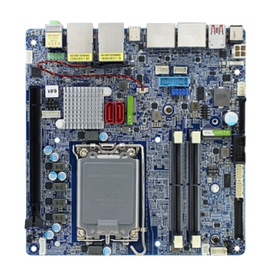
Page 20: Mainboard Layout (Top View)
MX680RD User’s Manual 1.4.2 Mainboard Layout (Top View) -
Page 21: Mainboard Layout (Bottom View)
MX680RD User’s Manual (Bottom View) -
Page 22: Layout Content List
MX680RD User’s Manual 1.4.3 Layout Content List • 1.4.3.1 Slots Label Function Note Page SODIMM_A1 262-pin DDR5 SODIMM slot 1 32MB maximum per slot SODIMM_B1 262-pin DDR5 SODIMM slot 2 32MB maximum per slot M2E1 M.2 Key-E Slot (2230) Supports PCIe x1, USB2.0, CNVi M2M1 M.2 Key-M Slot (2242/ 2280) -
Page 23: • 1.4.3.4 Internal Headers
MX680RD User’s Manual • 1.4.3.4 Internal Headers Label Note Page ATX12V1 ATX 4-Pins Power Connector 2 x 2 Mini Fit 4.20mm Straight Type Power Header. (12V~24V, A PSU with 23A min (34A for CPU peak current) on its “12V2” rail (for connecting with... -
Page 24: Back Panel Connectors (Rear I/O)
MX680RD User’s Manual • 1.4.3.5 Back Panel Connectors (Rear I/O) Label Function Note Page DC_IN1 DC-in Connector This connector is for AC Adapter DC_IN connection (12V~24V, 19V recommended, max) DC Mate Plug: DIA. 5.5mm (Outer) x 2.5mm (Inner). USB3_P910 USB 3.2 Connectors... -
Page 25: Central Processing Unit (Cpu)
PnP cap/socket pins/mainboard components. BCM will shoulder the cost of repair only, if the damage is shipment/ transit-related. • Keep the PnP cap after installing the mainboard. BCM will process Return Merchandise Authorization (RMA) requests only if the mainboard comes with the cap installed on the LGA1700 socket. -
Page 26: Installing The Cpu
MX680RD User’s Manual 1.5.1 Installing the CPU The CPU installation related information. 1. Locate the CPU socket (LGA1700 Socket) on the mainboard. 2. Press the load lever with your thumb at location (A), then move it toward right side (B) until it is released from the retention tab. - Page 27 MX680RD User’s Manual 3. Lift the load lever with your thumb and forefinger to around 120º angle (C), then pull the CPU Socket Cover (D) from the CPU socket. 4. Position the CPU over the socket, make sure that the gold triangle is on the top-left corner of the socket Then fit the socket alignment key with CPU notch.
- Page 28 MX680RD User’s Manual 5. Pull back the load lever down, then push the load lever (E) until it snaps into the retention tab. NOTE: The CPU fits in correct orientation only. DO NOT force the CPU into the socket to prevent bending the pins on the CPU socket and damaging the CPU and/or...
-
Page 29: Installing The Cpu Heatsink And Fan
MX680RD User’s Manual 1.5.2 Installing the CPU Heatsink and Fan The Intel LGA1700 processor requires a specially designed CPU heatsink and fan assembly to ensure optimum thermal condition and performance. • When you purchase a boxed Intel® processor, the package includes the CPU fan and heatsink assembly. - Page 30 MX680RD User’s Manual If the heatsink/fan assembly is installed through 4 screws, install two screws at a time in a diagonal sequence to secure the heatsink and fan assembly in place. If the heatsink/fan assembly is installed through fasteners, push down two fasteners at a time in a diagonal sequence into the 4 mounting holes around the CPU socket, then rotate each fastener clockwise to secure it with the mainboard.
- Page 31 MX680RD User’s Manual 3. Connect the CPU fan cable to the CPU fan connector on the mainboard labeled “CPU_FAN1”. NOTE: 1. Do not forget to connect the CPU fan connector. Insufficient air flow inside the system chassis may damage the mainboard components. Hardware monitoring errors can occur if you fail to plug in this connector.
-
Page 32: Uninstalling The Cpu Heatsink And Fan
MX680RD User’s Manual 1.5.4 Uninstalling the CPU Heatsink and Fan To uninstall the CPU heatsink and fan: 1. Disconnect the CPU fan cable from the CPU fan connector (“CPU_FAN1”) on the mainboard. 2A. If the heatsink/fan assembly is secured through 4 screws, loosen the screws. And then remove the hestsink/fan and its mounting plate from the mainboard. -
Page 33: System Memroy
MX680RD User’s Manual 1.6 System Memory 1.6.1 Overview The mainboard comes with two 262-pin Double Data Rate 5 (DDR5) Dual Inline Memory Modules (SODIMM) sockets. DDR5 memory brings several key performance and power gains to the table, as well as new design challenges. -
Page 34: Memory Configurations
MX680RD User’s Manual 1.6.2 Memory Configurations The MX680RD board supports 1.1V, Non-ECC or ECC, 262-pins DDR5-4800 SODIMM up to 64GB (32GB maximum/ slot). NOTE: 1. When two SODIMMs are being populated, only install identical (same type, same size, same CAS latency) DDR5 SODIMMs. -
Page 35: Installing The Ddr5 Sodimm
MX680RD User’s Manual 1.6.3 Installing the DDR5 SODIMM NOTE: Make sure to unplug the power connection before installing or removing SODIMMs, or other peripherals from the system. Failure to do so may cause severe damage to both the mainboard and the peripherals. -
Page 36: Uninstalling The Ddr5 Sodimm
MX680RD User’s Manual 1.6.4 Uninstalling the DDR5 SODIMM Follow these steps to remove SODIMM. 1. Press the two ejector tables on the socket outward simultaneously. 2. Pull out the SODIMM module from the socket. NOTE: Hold the SODIMM module gently when pressing the ejector tabs. The SODIMM might... -
Page 37: Power Supply
The connector is for ATX power supply plugs. The power supply plugs are designed to fit these connectors in only one orientation. Find the proper orientation and push down firmly until the connectors completely fit. The MX680RD board can be power on EITHER through: A. -
Page 38: Back Panel (Rear I/O Ports)
MX680RD User’s Manual Back Panel (Rear I/O Ports) 1.8.1 Back Panel Connectors Item Name Function Description DC_IN DC-in connector The connector is for DC_in (12V~24V) (19V recommended/ 8A max) DC Mate Plug: DIA. 5.5mm (Outer) x 2.5mm (Inner). USB3_P910 USB 3.2 Connectors... - Page 39 MX680RD User’s Manual LAN2 2.5G LAN This port allows 2.5G connection to a Local Area (RJ-45) Connectors Network (LAN) through a network hub. Refer to the table below for the LAN port LED indications. ACT/Link LED Speed LED Status Description...
-
Page 40: Connectors/ Headers
MX680RD User’s Manual Connectors/ Headers 1.9.1 Front Panel Connector: F_PANEL1 These connectors are for electrical connections to the front panel switches and LEDs. The “F_PANEL” connector is compliant with Intel® Front Panel I/O Connectivity Design Guide. • Power Button/Soft-off Button (Pin 6-8) This 2-pin connector is for the system power button. -
Page 41: M.2 Connectors: M2M1, M2E1, M2M2
MX680RD User’s Manual 1.9.2 M.2 Connectors: M2M1, M2E1, M2M2 The M.2 connectors provide different supports for PCIe, SATA III, and USB interfaces. Top Side: Bottom Side: Item Description Note M2E1 M.2 Key-E Slot (2230) Supports PCIe x1, USB2.0, CNVi M2M1 M.2 Key-M Slot (2242/ 2280) -
Page 42: Cpu & System Fan Connectors: Cpu_Fan1, Sys_Fan1
MX680RD User’s Manual 1.9.3 CPU & System Fan Connectors: CPU_FAN1, SYS_FAN1 The fan power connectors support system cooling fan with +12V. When connecting the wire to these fan connectors, please note that the red wire is designated as “Power” and should be connected to “+12V”... -
Page 43: Serial Ata 3.0 Connectors: Sata1, Sata2
MX680RD User’s Manual 1.9.4 Serial ATA 3.0 Connectors: SATA1, SATA2 SATA ports “SATA1”, “SATA2” support SATA3.0 standard. Do not fold the Serial ATA cable into 90-degree angle. Otherwise, data loss may occur during data transmission. 1.9.5 Front Panel Audio Connector: FP_AUDIO1 This connector is prepared for a chassis-mounted front panel audio I/O module that supports HD Audio standard. -
Page 44: Audio Amplifier Connector: Jamp1
MX680RD User’s Manual 1.9.6 Audio Amplifier Connector: JAMP1 This header provides amplified audio signals to external speakers (2-channels). The BIOS option “Amplifier GAIN (dB)” supports its volume control. 1.9.7 Front USB2.0 Header: USB1112 This header provides two USB2.0 connections (An USB2.0 cable is required). -
Page 45: Front Usb3.2 Header: Usb3_P56
MX680RD User’s Manual 1.9.8 Front USB3.2 Header: USB3_P56 This header provides two USB3.2 Gen 1 port connections (An USB3.2 cable is required). 1.9.9 Serial Port Connectors: COM1, COM2 These headers provides serial connections with serial port COM. COM1 supports RS232, RS422, RS485 protocols (selected through BIOS). -
Page 46: 1.9.10 Lvds Header: Lvds1
MX680RD User’s Manual 1.9.10 LVDS Header: LVDS1 This header provides connection to LVDS type panels. 1.9.11 LVDS Panel Backlight Connector: JBKL1 This header provides connection for LVDS panel backlight control connections. -
Page 47: Smbus Header: Smbus1
MX680RD User’s Manual 1.9.12 SMBUS Header: SMBUS1 This header provides SMBUS signal connections. 1.9.13 Digital I/O (GPIO) Header: JDIO1 This header provides a 8-bits input or output for general purposes. -
Page 48: I2C Header: I2C1
MX680RD User’s Manual 1.9.14 I2C Header: I2C1 This header provides I2C signal connections. 1.9.15 Chassis Intrusion Header: JCASE1 This 2-pins header provides chassis intrusion warning connection. -
Page 49: Jumpers
MX680RD User’s Manual 1.10 Jumpers 1.10.1 ATX/AT Mode Selection: JPSON1 This jumper provides the option to boot the system in the form of ATX mode (default) or AT mode. When the system is set in AT mode, the system power on/off will be controlled directly by the power switch on the power supply. -
Page 50: Lvds Brightness Control Mode Selection: Jlvds_Bkl1
MX680RD User’s Manual 1.10.3 LVDS Brightness Control Mode Selection: JLVDS_BKL1 This jumper provides the selection for control mode of LVDS backlight. 1.10.4 COM Mode Setting for COM1, COM2: RI_SEL1 This dip switch provides COM Mode settings for COM1, COM2 between “+12V”, “+5V”, or... -
Page 51: 1.10.5 Clear Cmos Header: Clcmos1
Here is the procedure for clear CMOS: 1. Turn off the system and unplug all power connections to MX680RD mainboard. 2. Disconnect the onboard battery from mainboard. 3. Relocate the jumper connector on “CLCMOS1” from pin 2-3 to pin 1-2 for at least 30 seconds. -
Page 52: The Expansion Slots
MX680RD User’s Manual 1.11 The Expansion Slots In the future, you may need to install expansion cards. The following sub-sections describe the expansion slots and the expansion cards that they support. NOTE: Make sure to unplug the power cord before adding or removing expansion cards. -
Page 53: Setup An Expansion Card
MX680RD User’s Manual 1.11.2 Setup an Expansion Card After installing the expansion card, configure it by adjusting the software settings. 1. Turn on the system and change the BIOS settings if necessary. See Chapter 2 for information on BIOS setup. -
Page 54: Chapter 2: Bios Setup
MX680RD User’s Manual Chapter 2: BIOS Setup BIOS Update Related Procedure After the BIOS is flashed, shut down the system. Disconnect all power connections from power supply to the mainboard. Clear the CMOS (For at least 30 seconds) (Check Section 1.10.5 for details). -
Page 55: Bios Setup Program
MX680RD User’s Manual BIOS Setup Program This motherboard supports a programmable firmware chip that you can update using the provided utility. Use the BIOS Setup program when you are installing a motherboard, reconfiguring your system, or prompted to “Run Setup.” This section explains how to configure your system using this utility. -
Page 56: Legend Box
MX680RD User’s Manual 2.1.1 Legend Box The keys in the legend bar allow you to navigate through the various setup menus Key(s) Function Description →← Select Screen ↑↓ Select Item Enter Select Change Opt. General Help Previous Values Optimal Defaults... -
Page 57: Bios Menu Screen
MX680RD User’s Manual BIOS Menu Screen When you enter the BIOS, the following screen appears. The BIOS menu screen displays the items that allow you to make changes to the system configuration. To access the menu items, press the up/down/right/left arrow key on the keyboard until the desired item is highlighted, then... -
Page 58: Main Menu
MX680RD User’s Manual Main Menu This menu gives you an overview of the general system specifications. The BIOS automatically detects the items in this menu. Use this menu for basic system configurations, such as time, date etc. -
Page 59: Advanced Bios Setup
MX680RD User’s Manual Advanced BIOS Setup Select the Advanced tab from the setup screen to enter the Advanced BIOS Setup screen. You can select any of the items in the left frame of the screen, such as Chipset configuration, to go to the sub menu for that item. You can display an Advanced BIOS Setup option by highlighting it using the <Arrow>... -
Page 60: Cpu Configuration
MX680RD User’s Manual 2.4.1 CPU Configuration Display CPU information and related setting 2.4.1.1 Intel (VMX) Virtualization [Enabled] When enabled, a VMX can utilize the additional hardware compatibilities provided by Vanderpool Technology Configuration options: [Enable] [Disable] 2.4.1.2 Active Performance-cores [All] Number of P-core to enable in each processor package 2.4.1.3 Active Efficient-cores [Enable]... -
Page 61: Hyper-Threading [Enabled]
MX680RD User’s Manual 2.4.1.4 Hyper-Threading [Enabled] Enable or disable Hyper-Threading technology Configuration options: [Enabled], [Disabled] 2.4.1.5 Intel Trusted Execution Technology [Disabled] Enabled utilization of additional hardware capabilities provided by Intel Trusted execution technology Configuration options: [Enabled], [Disabled] Some of the features might not be displayed on this BIOS menu, depending on the... -
Page 62: Power & Performance
MX680RD User’s Manual 2.4.2 Power & Performance Power management control for CPU 2.4.2.1 Intel® Speedstep™ [Enable] Allow more than two frequency range to be supported Configuration options: [Enable], [Disable] 2.4.2.2 Turbo Mode [Enable] Enable or Disable processor Turbo mode Configuration options: [Enable], [Disable] 2.4.2.3 C states [Enable]... -
Page 63: Enhance C States [Enable]
MX680RD User’s Manual 2.4.2.4 Enhance C states [Enable] When enabled, CPU will switch to minimum speed when all cores enter C state Configuration options: [Enable], [Disable] 2.4.2.5 Package C state limit [C3] Maximum package C state limit setting. Configuration options: [C0/C1], [C2], [C3]... -
Page 64: Pch-Fw Configuration
MX680RD User’s Manual 2.4.3 PCH-FW configuration Configure Management Engine Technology Parameters 2.4.3.1 ME State [Enabled] When disabled ME will be put into ME temporarily disabled mode Configuration options: [Enable], [Disable] 2.4.3.2 ME unlock control [Lock] When Set unlock, system will shut down for active function... -
Page 65: Trusted Computing
MX680RD User’s Manual 2.4.4 Trusted Computing Security device settings 2.4.4.1 TPM Device Selection [dTPM] Select TPM device between “dTPM” (Infineon TPM/ IFX), or “PTT” (Intel PTT/ INTC). The BIOS option “Security Device Support” (see below) needs to be enabled, and reboot system once in order to be able to change the setting of this BIOS option. -
Page 66: Security Device Support [Disable]
MX680RD User’s Manual 2.4.4.2 Security Device support [Disable] Enable or Disable BIOS support security device (TPM) Configuration options: [Enable], [Disable] NOTE: 1. When “Security Device Support” is enabled, it requires to save and exit BIOS once. And then And then reboot the system in order to initiate the TPM support at BIOS. -
Page 67: Acpi Settings
MX680RD User’s Manual 2.4.5 ACPI Settings 2.4.5.1 Enable Hibernation [Enable] Enable or Disable system ability to Hibernation. Configuration options: [Enable], [Disable] 2.4.5.2 ACPI Sleep State [S3 (Suspend to RAM)] Select the highest ACPI sleep state the system will enter the SUSPEND button is press. -
Page 68: Pcie# Wake From S5 [Disabled]
MX680RD User’s Manual 2.4.5.4 PCIE# wake from S5 [Disabled] Enable or disable PCIE wake the system from S5. Configuration options: [Disabled], [Enabled] 2.4.5.5 Wake on Ring [Disabled] Enable or disable wake on ring function under ACPI S3/S4/S5. Configuration options: [Disabled], [Enabled]... -
Page 69: Nct6126D Super Io Configuration
MX680RD User’s Manual 2.4.6 NCT6126D Super IO Configuration Provide NCT6126D super IO configuration settings 2.4.6.1 WatchDog Count Mode [Second] WatchDog count mode Selection Configuration options: [Second], [Minute] 2.4.6.2 WatchDog Timeout Value Fill watchdog timeout value 0 means disables 2.4.6.3 Chassis Opened Warning [Disabled]... -
Page 70: Serial Port 1 Configuration
MX680RD User’s Manual 2.4.6.4 Serial Port 1 Configuration 2.4.6.4.1 Serial Port [Enabled] Enable or Disable serial Port 1 (COM1) Configuration options: [Disabled], [Enabled]... -
Page 71: Change Settings [Auto]
MX680RD User’s Manual 2.4.6.4.2 Change Settings [Auto] Select an optimal settings for super IO device Configuration options: as picture below shown 2.4.6.4.3 COM Mode Select [RS232] Configure the COM port Mode Configuration options: [RS232], [RS485 Half Duplex], [RS422 Full Duplex]... -
Page 72: Serial Port 2 Configuration
MX680RD User’s Manual 2.4.6.5 Serial Port 2 Configuration 2.4.6.5.1 Serial Port [Enabled] Enable or Disable serial Port (COM) Configuration options: [Disabled] [Enabled]... -
Page 73: Change Settings [Auto]
MX680RD User’s Manual 2.4.6.5.2 Change Settings [Auto] Select an optimal settings for super IO device Configuration options: as picture below shown... -
Page 74: Hardware Monitor
MX680RD User’s Manual 2.4.7 Hardware Monitor Display Hardware monitor information... -
Page 75: Smart Fan
MX680RD User’s Manual 2.4.7.1 Smart FAN 2.4.7.1.1 Smart Fan Function [Enabled] Smart fan function Enable/Disabled Configuration options: [Enabled], [Disabled], [Manual]... -
Page 76: Smart Fan Mode Configuration
MX680RD User’s Manual 2.4.7.1.2 Smart Fan Mode Configuration Setting different FAN on this motherboard... -
Page 77: Cpu_Fan/Sys_Fan Smart Fan Target [55C]
MX680RD User’s Manual 2.4.7.1.2.1 CPU_FAN/SYS_FAN Smart FAN Target [55 C] Smart FAN target temperature setting Configuration options: Please see below picture... -
Page 78: Cpu_Fan/Sys_Fan Min.fan Speed (%) [12.5%]
MX680RD User’s Manual 2.4.7.1.2.2 CPU_FAN/SYS_FAN MIN.FAN Speed (%) [12.5%] CPU or Chassis Smart FAN minimum settings Configuration options: as picture below shown... -
Page 79: S5 Rtc Wake Settings
MX680RD User’s Manual 2.4.8 S5 RTC Wake Settings 2.4.8.1 Wake System from S5 [Disabled] Enabled or Disabled system wake on alarm event Configuration options: [Enabled], [Disabled]... -
Page 80: Serial Port Console Redirection
MX680RD User’s Manual 2.4.9 Serial Port Console Redirection Console redirection enable or disable 2.4.9.1 Console Redirection [Disabled] Enabled or Disabled COM1 Console redirection Configuration options: [Disabled], [Enabled]... -
Page 81: Console Redirection Settings
MX680RD User’s Manual 2.4.9.2 Console Redirection Settings 2.4.9.2.1 Terminal Type [ANSI] Select terminal type Configuration options: [VT100], [VT100Plus], [VT-UTF8], [ANSI] 2.4.9.2.2 Bits per second [115200] Select serial port transmission speed Configuration options: [9600], [19200], [38400], [57600], [115200] 2.4.9.2.3 Data Bits [8]... -
Page 82: Parity [None]
MX680RD User’s Manual 2.4.9.2.4 Parity [None] A parity bit can be sent with the data bits to detect some transmission errors Configuration options: [None], [Even], [Odd], [Mark], [Space] 2.4.9.2.5 Stop Bits [1] Stop bits indicate the end of a serial data package Configuration options: [1], [2] 2.4.9.2.6... -
Page 83: Intel Txt Information
MX680RD User’s Manual 2.4.10 Intel TXT Information Display Intel TXT information. This depends on CPU model installed onboard... -
Page 84: Usb Configuration
MX680RD User’s Manual 2.4.11 USB Configuration 2.4.11.1 USB Mass Storage Driver Support [Enabled] Enable or Disable USB Mass Storage Driver Support Configuration options: [Enabled], [Disabled] 2.4.11.2 Mass Storage Devices [Auto] Mass Storage device emulation Type. “Auto” enumerates device according to its media format. -
Page 85: Network Stack Configuration [Disabled]
MX680RD User’s Manual 2.4.12 Network Stack Configuration [Disabled] Network Stack setting 2.4.12.1 Network Stack [Disabled] Enabled/Disabled UEFI Network Stack Configuration options: [Enabled], [Disabled] 2.4.12.2 IPv4 PXE Support [Disabled] Enabled or disabled IPv4 PXE boot Support Configuration options: [Enabled], [Disabled] 2.4.12.3... -
Page 86: Pxe Boot Wait Time
MX680RD User’s Manual 2.4.12.4 PXE boot wait time Wait time in seconds to press ESC key to abort the PXE boot. 2.4.12.5 Media detect count Number of time the presence of media will be checked... -
Page 87: Nvme Configuration
MX680RD User’s Manual 2.4.13 NVMe Configuration Display NVMe controller or detected drive information... -
Page 88: Chipset
MX680RD User’s Manual Chipset... -
Page 89: System Agent (Sa) Configuration
MX680RD User’s Manual 2.5.1 System Agent (SA) Configuration 2.5.1.1 VT-d [Enabled] VT-d capability Configuration options: [Disabled], [Enabled] 2.5.1.2 Memory Configuration Memory Configuration parameters... -
Page 90: Max Tolud
MX680RD User’s Manual 2.5.1.2.1 Max TOLUD Maximum Value of TOLUD. Dynamic assignment would adjust TOLUD automatically based on largest MMIO length of installed graphic controller. -
Page 91: Graphic Configuration
MX680RD User’s Manual 2.5.1.3 Graphic Configuration Graphic configuration settings 2.5.1.3.1 Primary Display [Auto] Select which of IGFX/PEG/PCIE graphic device should be primary display or select HG for Hybrid Gfx. Configuration options: [Auto], [IGFX], [PEG slot], [PCIE] 2.5.1.3.2 Internal Graphics [Auto]... -
Page 92: Dvmt Pre-Allocaated [60M]
MX680RD User’s Manual 2.5.1.3.4 DVMT Pre-Allocated [60M] Select DVMT 5.0 Pre-allocated (Fixed) Graphics memory size used by the internal graphics device. Configuration options: As picture below shown... -
Page 93: Lcd Control
MX680RD User’s Manual 2.5.1.3.5 LCD Control 2.5.1.3.5.1 LCD Control [Disabled] Enable/Disable LCD. LCD is LVDS or eDP panel Configuration options: [Disabled], [Enabled]... -
Page 94: Vmd Setup Menu
MX680RD User’s Manual 2.5.1.4 VMD Setup Menu 2.5.1.4.1 Enable VMD Controller [Disabled] Enable/Disable to VMD controller Configuration options: [Disabled], [Enabled]... -
Page 95: Pci Express Configuration
MX680RD User’s Manual 2.5.1.5 PCI Express Configuration 2.5.1.5.1 Detect Non-Compliance Device [Disabled] Detect Non-compliance Device in PEG Configuration options: [Disabled], [Enabled]... -
Page 96: Pci Express Root Port 1 (X4 Key M)
MX680RD User’s Manual 2.5.1.5.2 PCI Express Root Port 1 (x4 Key M) 2.5.1.5.2.1 PCI Express Root Port 1 [Enabled] Control the PCI express Root Port Configuration options: [Enabled], [Disabled] 2.5.1.5.2.2 ASPM [Disabled] Set the ASPM level Configuration options: [Disabled], [L0S], [L1], [L0sL1] 2.5.1.5.2.3 PCIe Speed [Auto]... -
Page 97: Pci Express Root Port 2 (X16 Peg Slot)
MX680RD User’s Manual 2.5.1.5.3 PCI Express Root Port 2 (x16 PEG slot) 2.5.1.5.3.1 PCI Express Root Port 2 [Enabled] Control the PCI express Root Port Configuration options: [Enabled], [Disabled] 2.5.1.5.3.2 ASPM [Disabled] Set the ASPM level Configuration options: [Disaled], [L0S], [L1], [L0sL1] 2.5.1.5.3.3 PCIe Speed [Auto]... -
Page 98: Pch-Io Configuration
MX680RD User’s Manual 2.5.2 PCH-IO Configuration 2.5.2.1 LAN1 Controller [Enabled] Enable or Disable onboard LAN1 Configuration options: [Disabled], [Enabled] 2.5.2.2 LAN1 PXE OpROM [Disabled] Enabled or Disabled boot option for LAN1 controller Configuration options: [Disabled], [Enabled] 2.5.2.3 LAN2 Controller [Enabled]... -
Page 99: Lan2 Pxe Oprom [Disabled]
MX680RD User’s Manual 2.5.2.4 LAN2 PXE OpROM [Disabled] Enabled or Disabled boot option for LAN2 controller Configuration options: [Disabled], [Enabled] 2.5.2.5 Restore AC Power Loss [Power off] Specify what state to go to when power is re-applied after a power failure (G3 state) Configuration options: [Power on], [Power off], [Last State] 2.5.2.6... -
Page 100: Pci Express Configuration
MX680RD User’s Manual 2.5.2.9 PCI Express Configuration... -
Page 101: Pci Express Root Port 1 (X1 Key E)
MX680RD User’s Manual 2.5.2.9.1 PCI Express Root Port 1 (x1 Key E) 2.5.2.9.1.1 PCI Express Root Port 1 [Enabled] Control the PCI Express Port Configuration options: [Disabled], [Enabled] 2.5.2.9.1.2 ASPM 1 [Disabled] Set the ASPM level: Force L0s- Force all links to L0s State; Auto- BIOS auto configure;... -
Page 102: Detect Non-Compliance Device [Disabled]
MX680RD User’s Manual 2.5.2.9.1.4 Detect Non-Compliance Device [Disabled] Detect non-compliance PCI express Device, If enabled, it will take more time at Post time. Configuration options: [Disabled], [Enabled]... -
Page 103: Sata Configuration
MX680RD User’s Manual 2.5.2.10 SATA Configuration 2.5.2.10.1 SATA Controller(s) [Enabled] Enable or Disable SATA device Configuration options: [Enabled], [Disabled] 2.5.2.10.2 SATA Mode Selection [AHCI] Determines how SATA controller operate Configuration options: [AHCI] 2.5.2.10.3 M.2 Port [Enabled] Enable or Disable M.2 port... -
Page 104: Serial Ata Port 1 [Enabled]
MX680RD User’s Manual 2.5.2.10.4 Serial ATA Port 1 [Enabled] Enable or Disable SATA port 1 Configuration options: [Enabled], [Disabled] 2.5.2.10.5 Serial ATA Port 2 [Enabled] Enable or Disable SATA port 2 Configuration options: [Enable ], [Disabled] 2.5.2.10.6 M.2 Port [Enabled] Enable or Disable M.2 port... -
Page 105: Usb Configuration
MX680RD User’s Manual 2.5.2.11 USB Configuration 2.5.2.11.1 USB12 Standby Power [Enabled] Enable or Disable USB standby power Configuration options: [Disabled], [Enabled] 2.5.2.11.2 USB34 Standby Power [Enabled] Enable or Disable USB standby power Configuration options: [Disabled], [Enabled] 2.5.2.11.3 USB56 Standby Power [Enabled]... -
Page 106: Usb910 Standby Power [Enabled]
MX680RD User’s Manual 2.5.2.11.4 USB910 Standby Power [Enabled] Enable or Disable USB standby power Configuration options: [Disabled] [Enabled]... -
Page 107: Hd Audio Configuration
MX680RD User’s Manual 2.5.2.12 HD Audio Configuration 2.5.2.12.1 HD Audio [Enabled] Control Detection of the HD-Audio device. Configuration options: [Disabled], [Enabled]... -
Page 108: Serial Io Configuration
MX680RD User’s Manual 2.5.2.13 Serial IO Configuration 2.5.2.13.1 Serial IO I2C0 Controller [Enabled] Enabled/Disabled Serial IO Controller Configuration options: [Disabled], [Enabled] 2.5.2.13.2 Serial IO I2C2 Controller [Enabled] Enabled/Disabled Serial IO Controller Configuration options: [Disabled], [Enabled]... -
Page 109: Security
MX680RD User’s Manual Security 2.6.1 Administrator Password Set Administrator Password 2.6.2 User Password Set User Password... -
Page 110: Secure Boot
MX680RD User’s Manual 2.6.3 Secure Boot Secure Boot configuration. It usually requires user to provide the Secure Boot key to be implemented with a customized BIOS and the OS image. 2.6.3.1 Secure Boot [Disabled] Secure Boot feature is active if Secure Boot is enabled. Platform key (PK) is enrolled and the system is in user mode 2.6.3.2... -
Page 111: Reset To Setup Mode
MX680RD User’s Manual 2.6.3.4 Reset To Setup Mode Delete all Secure Boot Key databases from NVRAM 2.6.3.5 Key Management Enable expert users to modify Secure Boot policy variables without variable authentication... -
Page 112: Boot
MX680RD User’s Manual Boot 2.7.1 Setup Prompt Timeout [1] Number of seconds to wait for setup activation key. 65535(0xFFFF) means indefinite waiting. 2.7.2 Bootup NumLock State [On] Select the keyboard NumLock state Configuration options: [On], [Off] 2.7.3 Quiet Boot [Disable]... -
Page 113: Fixed Boot Order Priorities
MX680RD User’s Manual 2.7.5 Fixed BOOT ORDER Priorities The system will boot by the detected boot device with pre-set boot priorities accordingly. 2.7.6 UEFI USB Key Drive BBS Priorities Specifies the boot device priority sequence from available UEFI USB key Drives. -
Page 114: Save & Exit
MX680RD User’s Manual Save & Exit 2.8.1 Save Changes and Exit Exit system setup after saving the changes. 2.8.2 Discard Changes and Exit Exit system setup without saving any changes. 2.8.3 Save Changes and Reset Reset the system after saving the changes. -
Page 115: Load Optimized Default
MX680RD User’s Manual 2.8.4 Load Optimized Default Restore/Load default values for all the setup options. NOTE: Loading this option is recommended after BIOS update. Then load “Save changes and Exit” BIOS option. 2.8.5 Boot Override User can override the pre-set boot priority manually through this menu for detected boot devices. -
Page 116: Mebx
MX680RD User’s Manual MEBx Enter Intel MEBx (iAMT) menu. When entering this menu for the first time, the user password is “admin”, then user needs to setup a new password in order to access this menu next time. NOTE: 1. Intel® ME passwords must be between 8 and 32 characters long, have at least one upper case character, one lower case character, one number, and a special character (for example: !, @, #, $, %, ^, &, *). -
Page 117: Chapter 3: Application Note
Please read the following application notes before proceed with the system setup and/or OS installation: PXE Boot: 1. Connect ethernet cable with desired LAN1 or LAN2 port at rear I/O of MX680RD board. NOTE: Where “LAN1” is located right next to the rear I/O audio port. “LAN2” is located next to the rear I/O USB-C port (USB-P7). -
Page 118: Clear Cmos When A Different Model Of Cpu Is Install
Clear CMOS when a different model of CPU is installed: If a different model of CPU is being installed with the same MX680RD board, it is recommended to clear the CMOS once in order to be sure previous CPU information stored at NVRAM is cleared. -
Page 119: Multiple Displays (Through Intel Video Graphic)
Multiple Displays (through Intel Video Graphic): 1. Due to the limitations of Intel video driver, 4 display outputs are the maximum of multiple video outputs available with MX680RD board. 2. It is recommended that if user prefer to have multiple display outputs, the physical display devices (DP monitors, LVDS or eDP panels) can be connected to the desired video port before power on the system. -
Page 120: Intel Vmd (Raid)
9. Click on “Create Volume”. The BIOS will prompt with screen that shows “Volume1, RAID mode, storage capacity, normal”. 10. Save and exit BIOS. 11. Insert USB keys that contains the Win10 installation files and BCM provided driver “(OPTIONAL) RST_19.2.0.1003” to MX680RD board. 12. Turn-on system, the Win10 installation process begins. -
Page 121: The "Jamp1" Audio Header
MX680RD User’s Manual 17. After the Win10 installation is completed, install the Intel RST driver. The “JAMP1” audio header: When the rear I/O audio port is connected with speakers, there is no audio output on “JAMP1” header, unless the speaker connection on the rear I/O connection is disconnected.
Need help?
Do you have a question about the MX680RD and is the answer not in the manual?
Questions and answers