Table of Contents
Advertisement
Quick Links
Advertisement
Table of Contents

Related Manuals for BCM MX310H


Summary of Contents for BCM MX310H
- Page 1 MX310H User’s Manual MX310H Intel® H310 PCH Supports Coffee Lake (8th Gen)/ Coffee Lake Refresh (9th Gen) i7/i5/i3/Pentium processors (Supports “up to 6 Cores” and “up to TDP 65W” type processors only) Mini-iTX Motherboard User’s Manual Edition 1.00 – Sep, 2020...
- Page 2 Copyright Notice Copyright 2020 BCM Advanced Research, ALL RIGHTS RESERVED. No part of this document may be reproduced, copied, translated, or transmitted in any form or by any means, electronic or mechanical, for any purpose, without the prior written permission of the original manufacturer.
- Page 3 MX310H User’s Manual Disclaimer BCM Advanced Research reserves the right to make changes, without notice, to any product, including circuits and/or software described or contained in this manual in order to improve design and/or performance. BCM Advanced Research assumes no responsibility or liability for the use of the described...
- Page 4 BCM has come to be known. Your satisfaction is our primary concern. Here is a guide to BCM customer services. To ensure you get the full benefit of our services, please follow the instructions below carefully.
- Page 5 Because of BCM high quality-control standards and rigorous testing, most of our customers never need to use our repair service. If any of BCM products is defective, it will be repaired or replaced at no charge during the warranty period. For out-of-warranty repairs, you will be billed according to the cost of replacement materials, service time, and freight.
- Page 6 MX310H User’s Manual Manual Objectives This manual describes in detail the BCM MX310H Main board. We strongly recommend that you study this manual carefully before attempting to interface with this mainboard or change the standard configurations. Whilst all the necessary information is available in this manual we would recommend that unless you are confident, you contact your supplier for guidance.
-
Page 7: Table Of Contents
MX310H User’s Manual Contents Chapter 1: System Setup ....................Welcome! ............................14 Packing Contents .......................... 14 Before you proceed ........................15 Mainboard Overview ........................16 1.4.1 Mounting Holes ..........................16 1.4.2 Mainboard Layout (Top View/ Bottom View) ................17 1.4.3 Layout Content List ........................ - Page 8 MX310H User’s Manual 1.9.9 Front USB2.0 Headers: F_USB1, F_USB2 .................. 43 1.9.10 Serial Port Connector A: COMA ....................43 1.9.11 LVDS Header: LVDS ........................44 1.9.12 LVDS Panel Backlight Connector: BACKLIGHT ................44 1.9.13 SMBUS Header: SMBUS ......................45 1.9.14 GPIO Header: GPIO ........................
- Page 9 MX310H User’s Manual 3.7.7 CPU Configuration ........................61 3.7.7.1 Intel (VMX) Vitualization Technology .................... 61 3.7.7.2 Active Processor Cores ........................ 61 3.7.7.3 CPU Enhanced Halt (C1E) ......................61 3.7.7.4 Intel® Speed Shift Technology ..................... 62 3.7.7.5 C-State Control ..........................62 3.7.7.6...
- Page 10 MX310H User’s Manual 3.7.14 Plug in Devices Info ........................68 3.7.15 SATA & RST Configuration ......................68 3.7.15.1 SATA Controllers ........................... 68 3.7.15.2 SATA Mode Selection ........................68 3.7.15.3 Serial ATA Port 0 .......................... 68 3.7.15.4 Serial ATA Port 1 ........................... 68 3.7.15.5 Serial ATA Port 2 ..........................
- Page 11 MX310H User’s Manual 3.11 Save & Exit............................ 74 3.11.1 Save Changes and Exit ........................ 74 3.11.2 Exit Without Saving ........................74 3.11.3 Load Optimized Default ........................ 74 3.11.4 Boot override ..........................75 3.11.5 AMIFWUpdate..........................75 Chapter 4: Application Note ......................76 Windows 10 Drivers Installation ....................
- Page 12 MX310H User’s Manual Mainboard Specifications Model MX310H Processor Intel® H310 PCH Supports Coffee Lake (8th Gen) / Coffee Lake Refresh (9th Gen) i7/i5/i3/Pentium processors (Supports “up to 6 Cores” and “up to TDP 65W” type processors only) Chipset Intel® H310 PCH 2x 260-pins SODIMM sockets support 1.2V, Non-ECC, Un-buffered DDR4-2400...
- Page 13 MX310H User’s Manual 1 x TPM 2.0 Security Device (Infineon® TPM Chip SLB9665) Onboard I/O Headers SATA 4 x Std. SATA III Connectors (Some share SATA signal with M.2 connectors) 2 x USB2.0 Header (2 ports/header) RS232 1 x Header...
-
Page 14: Chapter 1: System Setup
This chapter describes the mainboard features and the new technologies it supports 1.1 Welcome! The mainboard delivers a host of new features and latest technologies, making it another line of BCM long life mainboards! Before you start installing the mainboard, and hardware devices on it, check the items in your package with the list below. -
Page 15: Before You Proceed
MX310H User’s Manual Before you proceed Take note of the following precautions before you install mainboard components or change any mainboard settings. • Unplug the power cord from the wall socket before touching any component inside the system. • Use a grounded wrist strap or touch a safely grounded object or to a metal object, such as the power supply case, before handling components to avoid damaging them due to static electricity. -
Page 16: Mainboard Overview
MX310H User’s Manual 1.4 Mainboard Overview Before you install the mainboard, study the configuration of your chassis to ensure that the mainboard fits into it. Make sure to unplug the power cord before installing or removing the mainboard. Failure to do so can cause you physical injury and damage mainboard components. -
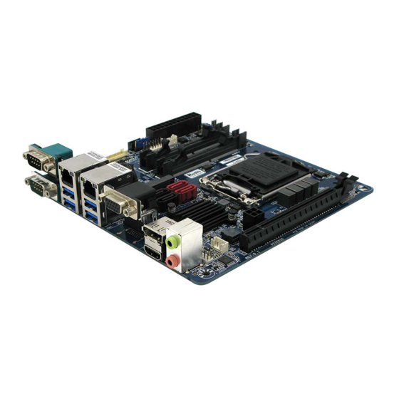
Page 17: Mainboard Layout (Top View/ Bottom View)
MX310H User’s Manual 1.4.2 Mainboard Layout (Top View) (Bottom View) -
Page 18: Layout Content List
MX310H User’s Manual 1.4.3 Layout Content List • 1.4.3.1 Slots Label Function Note Page DDR4_1 260-pin DDR4 SODIMM slot 1 16MB maximum per slot DDR4_2 260-pin DDR4 SODIMM slot 2 16MB maximum per slot MSATA_PCIE Supports MSATA SSDs Supports M.2 SATA SSDs... -
Page 19: Internal Headers
MX310H User’s Manual • 1.4.3.3 Internal Headers Label Function Note Page ATX_12V 12V ATX Power Connector 2 x 2 header, 24-pins ATX Power Connector 12 x 2 header CPU_FAN CPU Fan Connector 1 x 4 wafer, Pitch 2.54mm SYS_FAN System Fan Connector 1 x 4 wafer, Pitch 2.54mm... -
Page 20: Back Panel Connectors
MX310H User’s Manual • 1.4.3.4 Back Panel Connectors (Rear I/O) Label Function Note Page COMB Serial Port B COMC Serial Port C USB3.0 USB3.0 Ports (4 ports) LAN1 Gigabit LAN RJ-45 Connector (Intel i211) LAN2 Gigabit LAN RJ-45 Connector (Intel i219) -
Page 21: Central Processing Unit (Cpu)
PnP cap/socket pins/mainboard components. BCM will shoulder the cost of repair only, if the damage is shipment/ transit-related. • Keep the PnP cap after installing the mainboard. BCM will process Return Merchandise Authorization (RMA) requests only if the mainboard comes with the cap installed on the LGA1151 socket. -
Page 22: Installing The Cpu
MX310H User’s Manual 1.5.1 Installing the CPU The CPU installation related information. 1. Locate the CPU socket (LGA1151 Socket) on the mainboard. 2. Unlatch the “CPU Socket Lever” by pressing the lever down and move it away from the main structure of the socket. - Page 23 MX310H User’s Manual 3. Lift the load lever up in the direction of the arrow to a 135° angle, so the metal “CPU Socket Cover” can also be lifted. 4. The CPU socket has a plastic protection cap installed on it (black color, a.k.a. “CPU Socket Cover”, or “PnP cap”) in order to protect the socket pins from damage.
- Page 24 MX310H User’s Manual 5. There are two notches on the CPU itself (one on each side), and there are two “Socket Alignment keys” on the CPU socket as well. Line up the two CPU notches with the “Socket Alignment Keys” on the socket, and insert the CPU into the CPU socket slowly.
- Page 25 MX310H User’s Manual 7. Close the “CPU Socket Cover” by lowering down the “CPU Socket Lever”. Make sure the “CPU Socket Front Plates” are sliding underneath the “Shoulder Screw Cap”. 8. Secure the “CPU Socket Cover” by keep pressing down the “CPU Socket Lever” and move it toward and underneath the “Load Plate Tab”.
-
Page 26: Installing The Cpu Heatsink And Fan
MX310H User’s Manual 1.5.2 Installing the CPU Heatsink and Fan The Intel LGA1151 processor requires a specially designed heatsink and fan assembly to ensure optimum thermal condition and performance. • When you purchase a boxed Intel® processor, the package includes the CPU fan and heatsink assembly. - Page 27 MX310H User’s Manual Push down two fasteners at a time in a diagonal sequence to secure the heatsink and fan assembly in place Connect the CPU fan cable to the connector on the mainboard labeled “CPU_FAN”. A. Do not forget to connect the CPU fan connector. Insufficient air flow inside the system chassis may damage the mainboard components.
-
Page 28: Uninstalling The Cpu Heatsink And Fan
MX310H User’s Manual 1.5.3 Uninstalling the CPU Heatsink and Fan. To uninstall the CPU heatsink and fan: 1. Disconnect the CPU fan cable from the fan connector on the mainboard. 2. Rotate each fastener counterclockwise. 3. Pull up two fasteners at a time in a diagonal sequence to disengage the heatsink and fan assembly... - Page 29 MX310H User’s Manual 4. Rotate each fastener clockwise to ensure correct orientation when reinstalling. The narrow end of the groove should point outward after resetting. (The photo shows the groove shaded for emphasis.)
-
Page 30: System Memroy
MX310H User’s Manual System Memory 1.6.1 Overview The mainboard comes with two 260-pin Double Data Rate 4 (DDR4) Dual Inline Memory Modules (SODIMM) sockets. DDR4 SDRAM, an abbreviation for double data rate fourth generation synchronous dynamic random-access memory, is a type of synchronous dynamic random-access memory (SDRAM) with a high bandwidth (“double data rate”) interface. -
Page 31: Memory Configurations
MX310H User’s Manual 1.6.2 Memory Configurations The MX310H board supports 1.2V, Non-ECC, Un-buffered, 260-pins DDR4-2400 (PC4-19200, 2400MHz) SODIMM up to 32GB (16GB maximum/slot). • When there is only one DDR4 memory module being installed, it is recommended to install it on “DDR4_1” slot. -
Page 32: Installing The Ddr4 Sodimm
MX310H User’s Manual 1.6.3 Installing the DDR4 SODIMM Make sure to unplug the power supply before installing or removing SODIMMs, or other peripherals from the system. Failure to do so may cause severe damage to both the mainboard and the peripherals. -
Page 33: Removing The Ddr4 Sodimm
MX310H User’s Manual 1.6.4 Removing the DDR4 SODIMM Follow these steps to remove a SODIMM. Press the two ejector tables on the slot outward simultaneously Remove the SODIMM module from the socket. Hold the SODIMM module gently when pressing the ejector tabs. The SODIMM might... -
Page 34: Power Supply
MX310H User’s Manual Power Supply 1.7.1 ATX Power Connectors: ATX, ATX_12V These ATX power connectors provide connections from power supply unit (PSU) to the mainboard. Both connectors need to be installed in order for the mainboard to function properly. The power supply plugs are designed to fit with these ATX power connectors in one orientation only. -
Page 35: Back Panel (Rear I/O Ports)
MX310H User’s Manual Back Panel (Rear I/O Ports) 1.8.1 Back Pane Connectors Item Name Function Description COMC Serial Port Serial Port C. USB3.0 USB3.0 Ports The USB3.0 Port Connectors. USB3.0 USB3.0 Ports The USB3.0 Port Connectors. HDMI HDMI Port The HDMI Port Connector. - Page 36 MX310H User’s Manual Blinking Data Orange 1Gbps activity connection Item Name Function Description LAN1 Gigabit LAN This port allows Gigabit connection to a Local Area Network (Intel i211) (RJ-45) Connectors (LAN) through a network hub. Refer to the table below for the LAN port LED indications.
-
Page 37: Connectors/Headers
MX310H User’s Manual Connectors/ Headers 1.9.1 Front Panel Connectors: F_PANEL These connectors are for electrical connections to the front panel switches and LEDs. The “F_PANEL” connector is compliant with Intel® Front Panel I/O Connectivity Design Guide. -
Page 38: Cpu & System Fan Connectors: Cpu_Fan, Sys_Fan
MX310H User’s Manual 1.9.2 CPU & System Fan Connectors: CPU_FAN, SYS_FAN The fan power connectors support system cooling fan with +12V. When connecting the wire to these fan connectors, please note that the red wire is designated as “Power” and should be connected to “+12V”... -
Page 39: Serial Ata 3.0 Connectors: Sata3-0, Sata3-1, Sata3-2, Sata3-3
MX310H User’s Manual 1.9.3 Serial ATA 3.0 Connectors: SATA3-0, SATA3-1, SATA3-2, SATA3-3 SATA ports “SATA3-0”, “SATA3-1”, “SATA3-2”, “SATA3-3” support SATA3.0 standard. NOTE: 1. “SATA3-2” is sharing SATA signal with “MSATA_PCIE” connector, both headers can’t be connected with SATA device simultaneously (can only choose to use either one of these 2 headers). -
Page 40: Msata_Pcie Connector: Msata_Pcie
MX310H User’s Manual 1.9.4 MSATA_PCIE Connector: MSATA_PCIE This connector supports mSATA type SSDs. NOTE: “MSATA_PCIE” is sharing SATA signal with “SATA3-2” connector, both headers can’t be connected with SATA device simultaneously (can only choose to use either one of these 2 headers). -
Page 41: Cnvi Connector (E-Key, Supports Wifi Cards In 2230 Only): Cnvi
This connector supports WIFI cards in 2230. 1.9.6 M.2 SATA SSD Connector (On the Bottom Side of Board): M2A This M.2 connector is located at bottom side of MX310H board. It supports 2260/ 2280 SATA SSD Only (nVME type SSD is not supported). -
Page 42: Front Panel Audio Connector: F_Audio
MX310H User’s Manual 1.9.7 Front Panel Audio Connector: F_AUDIO This connector is prepared for a chassis-mounted front panel audio I/O module that supports HD Audio standard. Connect one end of the front panel audio I/O module cable to this connector. “F_AUDIO” volume can be adjusted through OS volume control. -
Page 43: Front Usb2.0 Headers: F_Usb1, F_Usb2
MX310H User’s Manual 1.9.9 Front USB2.0 Headers: F_USB1, F_USB2 This header provides two USB2.0 connections (An USB2.0 cable is required). Be sure the pins of USB+5V and GND signals on USB2.0 cable are connected to the corresponding USB2.0 headers correctly. Otherwise, it may cause damage to the USB port and/or the connected USB device. -
Page 44: Lvds Header: Lvds
MX310H User’s Manual 1.9.11 LVDS Header: LVDS This header provides connection to LVDS type panels (800x600 18-bit Single channel to 1920x1200 24-bit dual channel). 1.9.12 LVDS Panel Backlight Connector: BACKLIGHT This header provides connection for LVDS panel backlight control connections. -
Page 45: Smbus Header: Smbus
MX310H User’s Manual 1.9.13 SMBUS Header: SMBUS This header provides SMBUS signal connections. 1.9.14 GPIO Header: GPIO This header provides GPIO signal connections. -
Page 46: I2C Header: I2C
MX310H User’s Manual 1.9.15 I2C Header: I2C This header provides I2C signal connections. 1.9.16 Chassis Intrusion Header: CI This 2-pins header provides chassis intrusion warning connection. -
Page 47: Jumpers
MX310H User’s Manual 1.10 Jumpers 1.10.1 ATX/AT Mode Selection: AT_ATX This header provides the option to boot the system in the form of ATX mode (default) or AT mode. When the system is set in AT mode, the system power on/off will be controlled directly by the power switch on the power supply. -
Page 48: Com Ports +12V/ +5V Power Select: Coma_Pw, Comb_Pw, Comc_Pw
MX310H User’s Manual 1.10.3 COM Ports +12V/ +5V Power Select: COMA_PW, COMB_PW, COMC_PW These headers provide the options of selecting the COM port power in “+5V”, or “+12V” for corresponding COM port. -
Page 49: Clear Cmos Header: Clr_Cmos
For normal state (default), the jumper is set on pin location 2 and 3. To clear the CMOS, disconnect all power connections to MX310H first, then set the “CLR_CMOS” jumper to pin location 1 and 2 for at least 30 seconds while the system is Disconnected from the power. -
Page 50: The Expansion Slots
MX310H User’s Manual 1.11 The Expansion Slots In the future, you may need to install expansion cards. The following sub-sections describe the expansion slots and the expansion cards that they support. Make sure to unplug the power cord before adding or removing expansion cards. -
Page 51: Setup An Expansion Card
MX310H User’s Manual 1.11.2 Setup An Expansion Card After installing the expansion card, configure it by adjusting the software settings. 1. Turn on the system and change the BIOS settings if necessary. See Chapter 2 for information on BIOS setup. -
Page 52: Chapter 2: Starting Up The System
MX310H User’s Manual Chapter 2: Starting Up the System Starting Up Your System 1. After all connections are made, close your computer case cover. 2. Be sure all the switches are off, and check that the power supply input voltage is set to the local voltage, usually in-put voltage is 220V240V or 110V120V depending on your country’s... - Page 53 MX310H User’s Manual NOTE: During system power-on (system post), press <Del> key to enter BIOS setup. Follow the instructions in BIOS SETUP. If you wish to boot from a different bootable device other than the default arrangement under the BIOS, you may press <F11>...
-
Page 54: Chapter 3: Bios Setup
MX310H User’s Manual Chapter 3: BIOS Setup BIOS Flash Related Procedure 1. After the BIOS is flashed, shut down the system. 2. Disconnect all power connections from power supply to the mainboard. 3. Clear the CMOS (For at least 30 seconds). -
Page 55: Entering Bios Setup Menu
MX310H User’s Manual Entering BIOS Setup Menu Power on the computer and by pressing <DEL> immediately allows you to enter BIOS Setup Menu. If you are not able to enter the BIOS menu but you still wish to enter Setup, restart the system to try again by turning it OFF then ON or pressing the “RESET”... -
Page 56: Getting Help
MX310H User’s Manual Getting Help Main Menu The main menu lists the setup functions you can make changes to. You can use the arrow keys to select the item. The on-line description of the highlighted setup function is displayed at the bottom of the screen. -
Page 57: Bios Menu Screen
MX310H User’s Manual BIOS Menu Screen When entering the BIOS, the following screen appears. The BIOS menu screen displays the items that allow user to make changes to the system configuration. To access the menu items, press the up/down/right/left arrow key on the keyboard until the desired item is highlighted, then press [Enter] to... -
Page 58: Main Menu
MX310H User’s Manual Main Menu This menu gives user an overview of the general system specifications, such as time, date etc. 3.6.1 BIOS Information Displays the auto-detected BIOS information. 3.6.2 System Date The date format is in <Day>,<Month>,<Year>. 3.6.3 System Time... -
Page 59: Advanced Menu
MX310H User’s Manual Advanced Menu Select the “Advanced” tab from the BIOS menu screen to enter the Advanced BIOS Setup screen. NOTE: Take caution when change the settings of the Advanced menu items. Incorrect field values can cause the system not to function properly. -
Page 60: Watchdog
MX310H User’s Manual 3.7.3 Watchdog Enable/Disable Watch Dog feature. 3.7.4 Initial Display Output Select which video display output will be enabled during POST. 3.7.5 i211 Gigabit LAN Controller This option provides enable/disable control of onboard i211 Gigabit LAN controller (LAN1). -
Page 61: Cpu Configuration
MX310H User’s Manual 3.7.7 CPU Configuration This menu provides CPU related information and settings. 3.7.7.1 Intel (VMX) Virtualization Technology When enabled, a VMM can utilize the additional hardware capabilities provided by Vanderpool Technology. 3.7.7.2 Active Processor Cores Number of cores to enable in each processor package. -
Page 62: Intel® Speed Shift Technology
MX310H User’s Manual 3.7.7.4 Intel® Speed Shift Technology Enable/Disable Intel® Speed Shift Technology support. Enabling will expose the CPPC v2 interface to allow for hardware controlled P-states. 3.7.7.5 C-State Control C-State Control. 3.7.7.6 CPU EIST Function Intel’s EIST technology dynamically and effectively reduces the CPU Vcore and the CPU frequency to decrease the average power consumption and heat production. -
Page 63: Trusted Computing
MX310H User’s Manual 3.7.8 Trusted Computing Trust Computing (TPM) Settings. 3.7.8.1 Security Device Support Enable/disable the TPM support. NOTE: When “TPM Support” is enabled, it requires to save and exit BIOS once. And reboot the system in order to initiate the TPM support at BIOS. -
Page 64: Pc Health Status
MX310H User’s Manual 3.7.10 PC Health Status This option displays information about CPU/system voltage levels, temperatures detected at CPU, system, PCH, VRM MOS, and connected fan speed. 3.7.10.1 CPU Fan Speed Control Set CPU fan speed configurations. “Normal” mode (default): Fan speed set by BIOS default. -
Page 65: Cpu Temperature Control Interval
MX310H User’s Manual 3.7.10.3 CPU Temperature Control Interval This option provides CPU fan temperature sensitivity tolerance. Default Ranges: 0~3. 3.7.10.4 System Fan Speed Control Set System fan speed configurations. “Normal” mode (default): Fan speed set by BIOS default. “Silent” mode: Will reduce fan speed for quieter operation, but may raise temperature. -
Page 66: Super Io Configuration
MX310H User’s Manual 3.7.11 Super IO Configuration System Super IO chip parameters. 3.7.11.1 Serial Port A Configuration Set parameters of serial port A (Header “COMA”). 3.7.11.2 Serial Port B Configuration Set parameters of serial port B (rear I/O port “COMB”). -
Page 67: Network Stack Configuration
MX310H User’s Manual 3.7.13 Network Stack Configuration Network Stack settings. 3.7.13.1 IPv4 PXE Support Enable/Disable IPv4 PXE boot support. If disabled, IPv4 PXE boot support will not be available. 3.7.13.2 IPv4 HTTP Support Enable/Disable IPv4 HTTP boot support. If disabled, IPv4 HTTP boot support will not be available. -
Page 68: Plug In Devices Info
MX310H User’s Manual 3.7.14 Plug in Devices Info Show plug in devices info. 3.7.15 SATA & RST Configuration SATA device options settings. 3.7.15.1 SATA Controllers Enable/Disable SATA device. 3.7.15.2 SATA Mode Selection Determines how SATA Controller(s) operate. 3.7.15.3 Serial ATA Port 0 Enable or disable SATA Port0. -
Page 69: Chipset
MX310H User’s Manual Chipset The Chipset related BIOS options. 3.8.1 VT-d Intel VT-d support. 3.8.2 Internal Graphics Keep IGFX enabled based on the setup options. 3.8.3 LVDS Support LVDS support enabled/disabled. 3.8.4 LVDS Mode Select Select the supported resolution of connected LVDS panel. -
Page 70: Dvmt Pre-Allocated
MX310H User’s Manual 3.8.5 DVMT Pre-Allocated Select DVMT 5.0 Pre-Allocated (Fixed) graphic memory size used by the Internal graphics device. 3.8.6 DVMT Total Gfx Mem Select DVMT 5.0 total graphic memory size used by the internal graphic device. 3.8.7 Audio Controller Control detection of the HD-Audio device. -
Page 71: Security
MX310H User’s Manual Security If ONLY the Administrator’s password is set, then this only limits access to setup and is only asked for when entering setup. If ONLY the User’s password is set, then this is a power on password and must be entered to boot or enter setup. -
Page 72: Boot
MX310H User’s Manual 3.10 Boot Setup Boot related features. 3.10.1 Setup Prompt Timeout Number of second to wait for setup activation key. 3.10.2 Bootup NumLock State Select the keyboard NumLock state. 3.10.3 Full Screen LOGO Show Enable or disables Quiet Boot option. -
Page 73: Boot Mode Select
MX310H User’s Manual 3.10.5 Boot mode select Select boot mode in Legacy or UEFI (default). NOTE: If user needs to switch the boot mode between UEFI and Legacy; then user needs to select the desired boot mode first, then save and exit BIOS. The system needs to reboot once in order for the selected boot mode to take effect. -
Page 74: Save & Exit
MX310H User’s Manual 3.11 Save & Exit Save and Exit BIOS settings. 3.11.1 Save Changes and Exit Exit system setup after saving the changes. 3.11.2 Exit Without Saving Exit BIOS without saving any changes made. 3.11.3 Load Optimized Defaults Automatically load optimal BIOS settings. -
Page 75: Boot Override
MX310H User’s Manual 3.11.4 Boot Override Choose the desired boot device to be the first boot device at next reboot. NOTE: This function will only function once after rebooted. If user prefers to set the boot device boot order permanently, then the change will need to be made under “Boot” menu. -
Page 76: Chapter 4: Application Note
NOTE: If any of the driver listed above can’t be installed, you may update Win10 to the latest version through Windows Update by connecting ethernet cable to one of two MX310H onboard LANs. Display through PCIe video card (installed on “PCIEX16” slot) 1. -
Page 77: Boot Mode
PCIe video card. NOTE: 1. Due to the limitation of Intel video driver, the MX310H can only support maximum up to 2 video outputs simultaneously. 2. Besides the installed PCIex16 video card with its monitor connection, if you also have another dedicated monitor connected to one of MX310H’s video ports, both monitors... -
Page 78: The Header "Spkr
MX310H User’s Manual 5. After system reboot, enter BIOS again. 6. Under BIOS option “Boot”->”UEFI NETWORK Drive BBS Priorities”, set the desired PXE LAN port as “Boot Option #1”. 7. Press “ESC” key to get back to “Boot” menu. 8. Under BIOS option “Boot”->”Boot Option #1”; change the 1st boot device to the desired PXE LAN that selected under step 6. -
Page 79: The Connectors "Sata3-2" And "Msata_Pcie" Are Sharing The Sata Signals
MX310H User’s Manual The connectors “SATA3-2” and “MSATA_PCIE” are sharing the SATA signals 1. “SATA3-2” is sharing SATA signal with “MSATA_PCIE” connector, both headers can’t be connected with SATA device simultaneously (can only choose to use either one of these 2 headers) The connectors “SATA3-3”...
Need help?
Do you have a question about the MX310H and is the answer not in the manual?
Questions and answers