
Related Manuals for BCM MX3350N


Summary of Contents for BCM MX3350N
- Page 1 MX3350N Intel® Apollo Lake N3350 Mini-ITX Motherboard Mini-ITX Motherboard User’s Manual Edition 1.0 – July, 2017...
- Page 2 Copyright Notice Copyright 2011 BCM Advanced Research, ALL RIGHTS RESERVED. No part of this document may be reproduced, copied, translated, or transmitted in any form or by any means, electronic or mechanical, for any purpose, without the prior written permission of the original manufacturer.
- Page 3 Disclaimer BCM Advanced Research reserves the right to make changes, without notice, to any product, including circuits and/or software described or contained in this manual in order to improve design and/or performance. BCM Advanced Research assumes no responsibility or liability for the use of the described...
-
Page 4: Bcm Customer Services
BCM has come to be known. Your satisfaction is our primary concern. Here is a guide to BCM customer services. To ensure you get the full benefit of our services, please follow the instructions below carefully. -
Page 5: Product Warranty
Because of BCM high quality-control standards and rigorous testing, most of our customers never need to use our repair service. If any of BCM products is defective, it will be repaired or replaced at no charge during the warranty period. For out-of-warranty repairs, you will be billed according to the cost of replacement materials, service time, and freight. - Page 6 This manual describes in detail the BCM MX3350N Main board. We strongly recommend that you study this manual carefully before attempting to interface with MX3350N or change the standard configurations. Whilst all the necessary information is available in this manual we would recommend that unless you are confident, you contact your supplier for guidance.
- Page 7 Contents Chapter 1: System Setup .................... 11 1.1 Welcome! ......................... 11 1.2 Packing Contents ....................11 1.3 Features ........................12 1.4 Before you proceed ....................13 1.5 Mainboard Overview ....................14 1.5.1 Placement Direction ........................14 1.5.2 Mounting Holes ..........................15 1.5.3 Mainboard Layout ..........................
- Page 8 1.9.13 LVDS Connector: JLVDS1 ......................31 1.9.14 LPC Debug Port Connector: JTPM1 (With TPM Support) ............32 1.10 Jumpers ......................... 33 1.10.1 Clear CMOS Jumper: JCMOS1....................33 1.10.2 COM1, COM2, COM3 and COM4 Ring-in/ +12V/ +5V Power Select:......... 34 1.10.3 ATX/AT Mode Selection: JAT1 ....................34 1.10.4 Secondary RTC Reset Jumper: JBAT1 ..................
- Page 9 Mainboard Specifications Model MX3350N Processor Intel ® Celeron ® Processor N3350 Dual Core (up to 2.4GHz) Chipset 2 x DDR3L SO-DIMM slots (204 pin) Memory Dual channel Non-ECC DDR3L 1866/1600 MHz , Up to 16GB Display Intel® HD Graphic 3 x independent displays supported ■...
- Page 10 2 x 10/100/1000 LAN BIOS AMI BIOS AMI BIOS with 128Mb SPI ROM Digital IO 8-Bit (4 x GPI, 4 x GPO) Expansion Slots PCIe 1 x PCIe x 1 slot 1 x 2230 M.2 slot E Key with PCIe x1 & USB 2.0 signal 1 x 2280 &...
-
Page 11: Chapter 1: System Setup
This chapter describes the mainboard features and the new technologies it supports 1.1 Welcome! The mainboard delivers a host of new features and latest technologies, making it another line of BCM long life mainboards! Before you start installing the mainboard, and hardware devices on it, check the items in your package with the list below. -
Page 12: Features
• Drivers • Drivers is available for download at BCM website at WWW.BCMCOM.COM • Documentation • Manual is available for download at BCM website at WWW.BCMCOM.COM 1.3 Features MX3350N block Diagram... -
Page 13: Before You Proceed
1.4 Before you proceed Take note of the following precautions before you install mainboard components or change any mainboard settings. • Unplug the power cord from the wall socket before touching any component inside the system. • Use a grounded wrist strap or touch a safely grounded object or to a metal object, such as the power supply case, before handling components to avoid damaging them due to static electricity. -
Page 14: Mainboard Overview
1.5 Mainboard Overview Before you install the mainboard, study the configuration of your chassis to ensure that the mainboard fits into it. Make sure to unplug the power cord before installing or removing the mainboard. Failure to do so can cause you physical injury and damage mainboard components. 1.5.1 Placement Direction When installing the mainboard, make sure that you place it into the chassis in the correct orientation. -
Page 15: Mounting Holes
1.5.2 Mounting Holes Place the screws into the mounting holes indicated by red squares to secure the mainboard to the chassis. Do not over-tighten the screws! Doing so may damage the mainboard. -
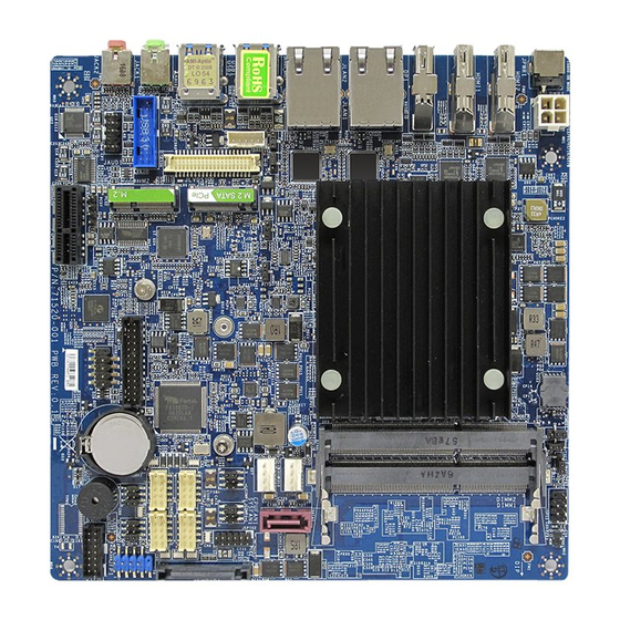
Page 16: Mainboard Layout
1.5.3 Mainboard Layout • Back Panel:... -
Page 17: Layout Content List
1.5.4 Layout Content List 1.5.4.1 Slots Label Function Note Page DIMM1 204-pin DIMM slot 1 If there is only one memory module being installed in the system, install it on this slot first. DIMM2 204-pin DIMM slot 2 PCI_E1 PCI express x1 slot M2_1 2230 M.2 slot E Key 2280 &... -
Page 18: Back Panel Connectors
JPSATA1 SATA Power 15-pin JFP1 System Panel Connector 2 x 5 header, pitch 2.54mm COM1 COM2 Serial Port Connector 1, 2, 3, 2 x 5 wafer, pitch 2.00mm COM3 COM4 JTPM1 LPC debug port and supports TPM 2 x 7 Box header, pitch 2.0mm modules JCASE1 Chassis Intrusion Connector... -
Page 20: Installing Dimm
1.6 Installing DIMM 1.6.1 The SO-DIMM slot is intended for memory modules. Locate the SO-DIMM slot. Align the notch on the DIMM with the key on the slot and insert the DIMM into the slot. Push the DIMM gently downwards until the slot levers click and lock the DIMM in place. -
Page 21: Power Supply
1.7 Power Supply 1.7.1 DC-In 12V Connector: PWR1 This connector is used to provide power to the motherboard. 1.7.2 SATA Power Connector: JPSATA1 This connector is used to provide power to SATA devices. Please use a SATA power cable connect onboard SATA power connector with SATA device’s power connector. -
Page 22: Back Panel
1.8 Back Panel 1.8.1 Back Panel Connectors Item Name Function Description JPWR1 DC-In 12V Jack This jack is used to provide power to motherboard. HDMI1 HDMI Port 1 The High-Definition Multimedia Interface (HDMI) is an all-digital audio/video interface capable of transmitting uncompressed streams. - Page 23 JLAN1/ Gigabit LAN This port allows Gigabit connection to a Local Area JLAN2 (RJ-45) Network (LAN) through a network hub. Refer to the Connectors table below for the LAN port LED indications. ACT/Link LED Speed LED Status Description Status Description No link 10Mbps connection...
-
Page 24: Connectors/ Headers
1.9 Connectors/ Headers 1.9.1 Serial ATA Connectors: SATA1 This connector is a high-speed Serial ATA interface port. Each connector can connect to one Serial ATA device. SATA3.0 standard, which is backward compatible with SATA2.0 Please do not fold the Serial ATA cable into 90-degree angle. Otherwise, data loss may occur during data transmission. -
Page 25: Fan Power Connectors: Cpufan1, Sysfan1
1.9.2 Fan Power Connectors: CPUFAN1, SYSFAN1 The fan power connectors support system cooling fan with +12V. When connecting the wire to these fan connectors, please note that the red wire is designated as “Power” and should be connected to “+12V” pin; the black wire is designated as “Ground”... -
Page 26: Chassis Intrusion Switch Connector: Jcase1
1.9.3 Chassis Intrusion Switch Connector: JCASE1 This connector connects to a 2-pin chassis switch. If the chassis is opened, the switch will be short. The system will record this status and show a warning message on the screen. To clear the warning message, you must enter the BIOS and clear the record. 1.9.4 Front Panel Audio Connector: JAUDIO1 This connector allows you to connect the front panel audio and is compliant with Intel®... -
Page 27: Amplifier Connector: Jamp1
1.9.5 Amplifier Connector: JAMP1 This header provided amplified audio signals to external speakers (2-channels). 1.9.6 Front USB2.0 Headers: JUSB1 This connector is compliant with Intel® I/O Connectivity Design Guide, which is ideal for connecting high-speed USB peripherals such as USB HDD, USB digital cameras, USB MP3 players, USB printers, etc. -
Page 28: Serial Port Connectors: Com1, Com2, Com3, Com4
1.9.7 Serial Port Connectors: COM1, COM2, COM3, COM4 This connector is a 16550A high speed communications port that sends/receives 16 bytes FIFOs. You can attach a serial device to it. COM1 supports RS232/422/485. COM2~4 support RS232. -
Page 29: Lpt Port Connector: Jlpt1
1.9.8 LPT Port Connector: JLPT1 The mainboard provides a 26-pin header for connection to an optional parallel port bracket. The parallel port is a standard printer port that supports Enhanced Parallel Port (EPP) and Extended Capabilities Parallel Port (ECP) mode. 1.9.9 Front Panel Connectors: JFP1 This front panel connector is provided for electrical connection to the front panel switches &... -
Page 30: Usb3.0 Connector: Jusb3
1.9.10 USB3.0 Connector: JUSB3 The USB3.0 port is backwards compatible with USB2.0 devices. It supports up to 5 Gbit/s (Su- perSpeed) data transfer rate. 1. Note that the pins of VCC and GND must be connected correctly to avoid possible damage. -
Page 31: Lvds Inverter Connector: Jinv1
1.9.12 LVDS Inverter Connector: JINV1 The connector is provided for LCD backlight options. 1.9.13 LVDS Connector: JLVDS1 The LVDS (Low Voltage Differential Signal) connector provides a digital interface typically used with flat panels. After connecting an LVDS interface flat panel to the JLVDS1, be sure to check the panel datasheet and set the LVDS jumper to proper power voltage. -
Page 32: Lpc Debug Port Connector: Jtpm1 (With Tpm Support)
1.9.14 LPC Debug Port Connector: JTPM1 (With TPM Support) This connector works as LPC debug port and supports TPM modules through an adapter. -
Page 33: Jumpers
1.10 Jumpers 1.10.1 Clear CMOS Jumper: JCMOS1 There is a CMOS RAM onboard that has a power supply from an external battery to keep the data of system configuration. For normal state (default), the jumper is set on pin location 1 and 2. To clear the CMOS, set the jumper to pin location 2 and 3 for at least 30 seconds while the system is off. -
Page 34: Com1, Com2, Com3 And Com4 Ring-In/ +12V/ +5V Power Select
1.10.2 COM1, COM2, COM3 and COM4 Ring-in/ +12V/ +5V Power Select: JCOMP1, JCOMP2, JCOMP3, JCOMP4 These headers provide ring-in, or 5V, or 12V on the com ports. 1.10.3 ATX/AT Mode Selection: JAT1 This header provides the option to boot the system in the form of ATX mode (default) or AT mode. When the system is set in AT mode, the system power on/off will be controlled directly by the power switch on power supply. -
Page 35: Secondary Rtc Reset Jumper: Jbat1
1.10.4 Secondary RTC Reset Jumper: JBAT1 When the RTC battery is removed, this jumper resets the manageability register bits in the RTC. 1.10.5 TXE F/W Jumper: JTXE1 This jumper is used to enable/disable the Intel TXE F/W. -
Page 36: Lvds Backlight Power Jumper: Jbklvol1
1.10.6 LVDS Backlight Power Jumper: JBKLVOL1 Use this jumper to specify the operation voltage of the LVDS display. 1.10.7 LVDS Backlight Control Jumper: JLVDS_BKL1 Use this jumper to specify the backlight control of the LVDS display. -
Page 37: The Expansion Slots
1.11 The Expansion Slots In the future, you may need to install expansion cards. The following sub-sections describe the expansion slots and the expansion cards that they support. Make sure to unplug the power cord before adding or removing expansion cards. Failure to do so may cause you physical injury and damage mainrboard components. -
Page 38: Pci-E X1 Slot: Pci_E1
1.11.3 PCIe x1 Slot: PCI_E1 The PCI Express slot supports PCIe interface expansion cards. 1.11.4 M.2 Slot (Key M, 2280 & 2242): JM1 Please install the M.2 solid-state drive (SSD) into the M.2 slot as shown below. 1. When adding or removing expansion cards, make sure the system power is OFF. 2. -
Page 39: M.2 Slot (Key E, 2230): M2_1
1.11.5 M.2 Slot (Key E, 2230): M2_1 Please install the Wi-Fi/ Bluetooch card into the M.2 slot as shown below. When adding or removing expansion cards, make sure that you unplug the power supply first. Meanwhile, read the documentation for the expansion card to configure any necessary hardware or software settings for the expansion card, such as jumpers, switches or BIOS configuration. -
Page 40: Chapter 2: Starting Up The System
Chapter 2: Starting Up the System Starting Up Your System After all connections are made, close your computer case cover. Connect the power supply cord into the power supply located on the back of your system case according to your system user’s manual. Turn on your peripheral in following order: Your monitor. -
Page 42: Chapter 3: Bios Setup
Chapter 3: BIOS SETUP This chapter provides information on the BIOS Setup program and allows users to configure the system for optimal use. Users may need to run the BIOS Setup when: 1. An error message appears on the screen at system startup and requests users to run SETUP. 2. -
Page 43: Getting Help
Getting Help After entering the Setup menu, the first menu you will see is the Main Menu. Main Menu The main menu lists the setup functions you can make changes to. You can use the arrow keys ( ↑↓ ) to select the item. -
Page 44: The Menu Bar
3.1 The Menu Bar ▶ Main Use this menu for basic system configurations, such as time, date, etc. ▶ Advanced Use this menu to set up the items of special enhanced features. ▶ Boot Use this menu to specify the priority of boot devices. ▶... -
Page 45: Main
3.2 Main ▶ System Date This setting allows you to set the system date. The date format is <Day>, <Month> <Date> <Year>. ▶ System Time This setting allows you to set the system time. The time format is <Hour> <Minute> <Second>. ▶... -
Page 46: Advanced
3.3 Advanced ▶ Full Screen Logo Display This BIOS feature determines if the BIOS should hide the normal POST messages with the motherboard or system manufacturer’s full-screen logo. When it is enabled, the BIOS will display the full-screen logo during the boot-up sequence, hiding normal POST messages. - Page 47 ▶ Super IO Configuration ▶ Serial Port 1/ 2/ 3/ 4 This setting enables/disables the specified serial port. ▶ Change Settings This setting is used to change the address & IRQ settings of the specified serial port. ▶ Mode Select Select an operation mode for the Serial Port 1.
- Page 48 ▶ H/W Monitor These items display the current status of all monitored hardware devices/ components such as voltages, temperatures and all fans’ speeds. ▶ Smart Fan Configuration ▶ Smart CPUFAN Target, Smart SYSFAN Target The setting enables/disables the Smart Fan function. Smart Fan is an excellent feature which will adjust the CPU/system fan speed automatically depending on the current CPU/system temperature, avoiding the overheating to damage your system.
- Page 49 ▶ CPU Configuration ▶ Intel Virtualization Technology Virtualization enhanced by Intel Virtualization Technology will allow a platform to run multiple operating systems and applications in independent partitions. With virtualization, one computer system can function as multiple “Virtual” systems. ▶ EIST EIST (Enhanced Intel SpeedStep Technology) allows the system to dynamically adjust processor voltage and core frequency, which can result in decreased average power consumption and decreased average heat production.
- Page 50 ▶ Network Stack Configuration ▶ Network Stack The setting enables/disables UEFI Network Stack. ▶ Ipv4 PXE Support, Ipv4 HTTP Support, Ipv6 PXE Support, Ipv6 HTTP Support The setting enables/disables Ipv4 PXE Support, Ipv4 HTTP Support, Ipv6 PXE Support and Ipv6 HTTP Support.
- Page 51 ▶ USB Configuration ▶ Legacy USB Support Set to [Enabled] if you need to use any USB 1.1/2.0 device in the operating system that does not support or have any USB 1.1/2.0 driver installed, such as DOS and SCO Unix. ▶...
- Page 52 ▶ PCI/PCIE Device Configuration ▶ Audio Controller This setting enables/disables the onboard audio controller. ▶ Launch OnBoard LAN OpROM These settings enable/disable the initialization of the onboard/onchip LAN Boot ROM during bootup. Selecting [Disabled] will speed up the boot process. ▶...
-
Page 53: Boot
3.4 Boot ▶ CSM Support This setting enables/disables the support for Compatibility Support Module, a part of the Intel Platform Innovation Framework for EFI providing the capability to support legacy BIOS interfaces. ▶ OS Selection This setting allows users to select the Operating System. ▶... -
Page 54: Security
3.5 Security ▶ Administrator Password Administrator Password controls access to the BIOS Setup utility. ▶ User Password User Password controls access to the system at boot and to the BIOS Setup utility. ▶ Chassis Intrusion The field enables or disables the feature of recording the chassis intrusion status and issuing a warning message if the chassis is once opened. - Page 55 ▶ Trusted Computing ▶ Security Device Support This setting enables/disables BIOS support for security device. When set to [Disable], the OS will not show security device. TCG EFI protocol and INT1A interface will not be available. ▶ SHA-1 PCR Bank, SHA256 PCR Bank These settings enable/disable the SHA-1 PCR Bank and SHA256 PCR Bank.
- Page 56 ▶ Serial Port Console Redirection ▶ Console Redirection Console Redirection operates in host systems that do not have a monitor and keyboard attached. This setting enables/disables the operation of console redirection. When set to [Enabled], BIOS redirects and sends all contents that should be displayed on the screen to the serial COM port for display on the terminal screen.
- Page 57 ▶ Terminal Type To operate the system’s console redirection, you need a terminal supporting ANSI terminal protocol and a RS-232 null modem cable connected between the host system and terminal(s). This setting specifies the type of terminal device for console redirection. ▶...
- Page 58 ▶ Security Configuration ▶ TXE FW Version The setting shows the firmware information of the Intel Trusted Execution Engine (TXE). ▶ TXE HMRFPO The setting enables/disables TXE HMRFPO (Host ME Region Flash Protection Override). ▶ TXE EOP Message This setting determines whether or not to send EOP (Exchange Online Protection) message before entering OS.
-
Page 59: Chipset
3.6 Chipset ▶ DVMT Pre-Allocated This setting defines the DVMT pre-allocated memory. Pre-allocated memory is the small amount of system memory made available at boot time by the system BIOS for video. Pre-allocated memory is also known as locked memory. This is because it is "locked" for video use only and as such, is invisible and unable to be used by the operating system. -
Page 60: Power
3.7 Power ▶ Restore AC Power Loss This setting specifies whether your system will reboot after a power failure or interrupt occurs. Available settings are: [Power Off] Leaves the computer in the power off state. [Power On] Leaves the computer in the power on state. [Last State] Restores the system to the previous status before power failure or interrupt occurred. - Page 61 ** Advanced Resume Events Control ** ▶ PCIE PME This field specifies whether the system will be awakened from power saving modes when activity or input signal of onboard PCIE PME is detected. ▶ USB from S3/S4 The item allows the activity of the USB device to wake up the system from S3/ S4 sleep state. ▶...
-
Page 62: Save & Exit
3.8 Save & Exit ▶ Save Changes and Reset Save changes to CMOS and reset the system. ▶ Discard Changes and Exit Abandon all changes and exit the Setup Utility. ▶ Discard Changes Abandon all changes. ▶ Load Optimized Defaults Use this menu to load the default values set by the motherboard manufacturer specifically for optimal performance of the motherboard. -
Page 63: Chapter 4: Wdt&Gpio
Chapter 4: WDT&GPIO 4.1 WDT Sample Code SIO_INDEX_Port equ 04Eh SIO_DATA_Port equ 04Fh SIO_UnLock_Value equ 087h SIO_Lock_Value equ 0AAh WatchDog_LDN equ 007h WDT_UNIT equ 60h ;60h=second, 68h=minute, 40h=Disabled Watchdog timer WDT_Timer equ 30 ;ex. 30 seconds Sample code: ;Enable config mode dx, SIO_INDEX_Port al, SIO_UnLock_Value dx, al... - Page 64 ;set timer dx, SIO_INDEX_Port al, 0F6h dx, al dx, SIO_DATA_Port al, WDT_Timer dx, al ;set UINT dx, SIO_INDEX_Port al, 0F5h dx, al dx, SIO_DATA_Port al, WDT_UNIT dx, al ;enable reset dx, SIO_INDEX_Port al, 0FAh dx, al dx, SIO_DATA_Port al, dx al, 01h dx, al ;close config mode...
-
Page 65: Gpio Sample Code
4.2 GPIO Sample Code GPI 0 ~ GPI 3 GPI 0 GPI 1 GPI 2 GPI 3 IO Address SIO GPIO Register 92h Sample code GPO 0 ~ GPO 3 GPO 0 GPO 1 GPO 2 GPO 3 IO Address SIO GPIO Register A2h Sample code SIO_INDEX_Port... -
Page 66: Sample Code
Sample Code: #1 : Get GPI 0 status ; Enable config mode mov dx, SIO_INDEX_Port mov al, SIO_UnLock_Value out dx, al jmp short $+2 ;Io_delay jmp short $+2 ;Io_delay out dx, al ; Switch GPIO Configuration for SIO LDN 0x06 mov dx, SIO_INDEX_Port mov al, 07h out dx, al... - Page 67 jmp short $+2 ;Io_delay jmp short $+2 ;Io_delay out dx, al ; Switch GPIO Configuration for SIO LDN 0x06 mov dx, SIO_INDEX_Port mov al, 07h out dx, al mov dx, SIO_DATA_Port mov al, SIO_LDN_GPIO out dx, al ; Set GPO 0 to high mov dx, SIO_INDEX_Port mov al, SIO_GPO_Data out dx, al...
Need help?
Do you have a question about the MX3350N and is the answer not in the manual?
Questions and answers