
Subscribe to Our Youtube Channel
Related Manuals for BCM MX1900J


Summary of Contents for BCM MX1900J
- Page 1 MX1900J Intel® Bay Trail-D Celeron J1900 SoC Mini iTX Motherboard User’s Manual Edition 1.00 – Oct, 2014...
- Page 2 Copyright Notice Copyright © 2011 BCM Advanced Research, ALL RIGHTS RESERVED. No part of this document may be reproduced, copied, translated, or transmitted in any form or by any means, electronic or mechanical, for any purpose, without the prior written permission of the original manufacturer.
- Page 3 Disclaimer BCM Advanced Research reserves the right to make changes, without notice, to any product, including circuits and/or software described or contained in this manual in order to improve design and/or performance. BCM Advanced Research assumes no responsibility or liability for the use of the described...
-
Page 4: Bcm Customer Services
BCM has come to be known. Your satisfaction is our primary concern. Here is a guide to BCM customer services. To ensure you get the full benefit of our services, please follow the instructions below carefully. -
Page 5: Product Warranty
Because of BCM high quality-control standards and rigorous testing, most of our customers never need to use our repair service. If any of BCM products is defective, it will be repaired or replaced at no charge during the warranty period. For out-of-warranty repairs, you will be billed according to the cost of replacement materials, service time, and freight. - Page 6 This manual describes in detail the BCM MX1900J Main board. We strongly recommend that you study this manual carefully before attempting to interface with MX1900J or change the standard configurations. Whilst all the necessary information is available in this manual we would recommend that unless you are confident, you contact your supplier for guidance.
-
Page 7: Table Of Contents
Contents Chapter 1: System Setup ....................Welcome! ............................12 Packing Contents .......................... 12 Special Features ........................... 13 1.3.1 Product Overview .......................... 13 Before you proceed ........................15 Mainboard Overview ........................16 1.5.1 Mounting Holes ..........................16 1.5.2 Mainboard Layout ......................... 17 1.5.3 Layout Content List ........................ - Page 8 1.9.11 LVDS Header: JLVDS1 ......................... 33 1.9.12 Digital I/O Connector: JDIO1 ......................34 1.9.13 The Header: JPSONLOCK1 ......................34 1.10 Jumpers ............................35 1.10.1 ATX/AT Mode Selection: JPSON1 ....................35 1.10.2 Clear CMOS Jumper: CLCMOS1 ....................36 1.10.3 COM1 Ring-In/ +12V/ +5V Select: JCOMPWR1 ................37 1.10.4 mSATA Mode Select: JSATA1 .....................
- Page 9 3.7.10.1 Smart Fan Mode Configurtion ....................... 64 3.7.11 USB Configuration ........................66 Chipset ............................68 3.8.1 North Bridge ..........................69 3.8.1.1 Intel IGD onfiguration ........................70 3.8.1.2 Boot Display Control ........................71 3.8.2 South Bridge ..........................72 3.8.2.1 Azalia HD Audio ..........................73 3.8.2.2 USB Configuration ........................
- Page 10 Mainboard Specifications Model MX1900J Processor Intel® Celeron® J1900 Processor onboard 2 GHz (Intel® Bay Trail-D Platform) Chipset 2 x 204Pin SODIMM sockets supports DDR3 memory module (1.35V ONLY) 1333 Memory MHz up to 8GB (4GB maximum/slot) Display Intel® Integrated Graphic Engine...
- Page 11 2 x USB2.0 Headers (4 ports on headers) RS232 1 x Headers 1 x Header Front Audio 1 x Header Amplifier 1 x Header Front Panel 1 x Header Fan Header 2 x Headers (4-pins) LVDS 1 x Header Inverter Connection Port 1 x Header Onboard Jumpers COM Port Ring-In/ Power Select...
-
Page 12: Chapter 1: System Setup
This chapter describes the mainboard features and the new technologies it supports 1.1 Welcome! The mainboard delivers a host of new features and latest technologies, making it another line of BCM long life mainboards! Before you start installing the mainboard, and hardware devices on it, check the items in your package with the list below. -
Page 13: Special Features
1.3 Product Highlights 1.3.1 Product Overview MX1900J is equipped with quad-core Intel® Celeron® desktop J1900 processor (formerly codenamed BayTrail-D) with speeds of 2.0 GHz delivering outstanding computing, graphical and media performance in a compact and economically efficient form factor. The J1900 technology is a 22nm, leading-edge, and low-power system-on-a chip (SoC) solution designed based on the 4th generation Intel®... - Page 14 • Trusted Platform Module (TPM) Support By combining the onboard TPM 1.2 with TPM security software (provided by the third party), it will enhance the security level of the system. • PRECAUTION: When TPM is enabled and utilized through TPM software, there is possibility that the encrypted data will not be accessible, or recoverable if one of the following situations occurred: 1.
-
Page 15: Before You Proceed
Before you proceed Take note of the following precautions before you install mainboard components or change any mainboard settings. • Unplug the power cord from the wall socket before touching any component inside the system. • Use a grounded wrist strap or touch a safely grounded object or to a metal object, such as the power supply case, before handling components to avoid damaging them due to static electricity. -
Page 16: Mainboard Overview
Mainboard Overview Before you install the mainboard, study the configuration of your chassis to ensure that the mainboard fits into it. Make sure to unplug the power cord before installing or removing the mainboard. Failure to do so can cause you physical injury and damage mainboard components. 1.5.1 Mounting Holes Place the screws into the mounting holes indicated by red squares to secure the mainboard to the chassis. -
Page 17: Mainboard Layout
1.5.2 Mainboard Layout... -
Page 18: Layout Content List
1.5.3 Layout Content List • 1.5.3.1 Slots Label Function Note Page SODIMM_A1 240-pin DDR3L SODIMM slot A1 1. If there is only one memory module being installed in the system, install it on this slot. SODIMM_B1 240-pin DDR3L SODIMM slot B1 MINI_CARD1 Mini PCIe Slot for FULL size card MINI_CARD2... -
Page 19: Back Panel Connectors
JDIO1 Digital I/O Connector 6 x 2 header, pitch 2.00mm JLVDS1 LVDS Panel Connector 20 x 2 header, 1.25mm pitch wire to board connector (WTB) JBKL1 Panel Backlight Connector 5 x 1 header, pitch 2.00mm JPSONLOCK1 PSON Connector 2 x 1 header •... -
Page 20: System Memroy
System Memory 1.6.1 Overview The mainboard comes with two 204-pin Double Data Rate 3 Low voltage (DDR3L) Dual Inline Memory Modules (SODIMM) sockets. A DDR3L module has the same physical dimensions as a DDR SODIMM but has a 204-pin footprint compared to the 240-pin DDR2 DIMM. -
Page 21: Memory Configurations
You may ONLY install 1GB, 2GB, or 4GB DDR3L-1333MHz (PC3-10600); Non-ECC, Un-buffered 1.35V DDR3L memory modules on this board (4GB maximum for each slot). MX1900J does not support DDR/ DDR2/ DDR3 SODIMM modules, DO NOT install DDR/ DDR2/ DDR3 SODIMM modules on this board. -
Page 22: Installing The Ddr3L Sodimm
1.6.3 Installing the DDR3L SODIMM Make sure to unplug the power supply before adding or removing SODIMMs or other peripherals from the system. Failure to do so may cause severe damage to both the mainboard and the peripherals. 1. Locate the SODIMM socket onboard. 2. -
Page 23: Removing The Ddr3L Sodimm
1.6.4 Removing the DDR3L SODIMM Follow these steps to remove a SODIMM. 1. Press the two ejector tables on the slot outward simultaneously 2. Remove the SODIMM module from the socket. Hold the SODIMM module gently when pressing the ejector tabs. The SODIMM might get damaged when it flips out with extra force. -
Page 24: Power Supply
Find the proper orientation and push down firmly until the connector is completely fit. In order to power on MX1900J through this connector, the signal “PSON” must be connected with the “GND” signal on the 20/24 pin ATX power connector. -
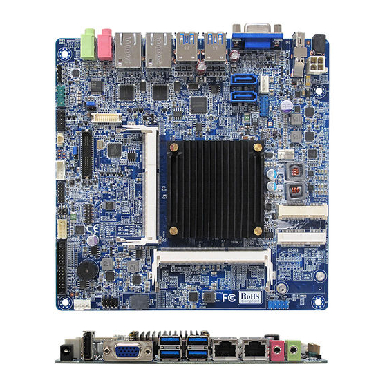
Page 25: Back Panel
Back Panel 1.8.1 Back Panel Connectors Item Name Function Description AC Power The port is for an AC power adapter (DC Output Adapter 12.0V/5.0A). Connector Display Port The display port Connector VGA1 VGA Video Port The VGA15-pin Connector. USB34 USB 3.0 These two 4-pin Universal Serial Bus (USB) ports Connectors are available for connecting USB 3.0 devices. - Page 26 Status Description Status Description No link 10Mbps connection Orange Linked Green 100Mbps connection Blinking Data Orange 1Gbps activity connection AUDIO2 Microphone port This port connects a microphone. (Pink) AUDIO1 Line-out port This port connects a headphone or a speaker. (Lime)
-
Page 27: Connectors/Headers
Connectors/ Headers 1.9.1 Serial ATA 2.0 Connectors: SATA1, SATA2 SATA ports “SATA1” and “SATA2” support SATA2.0 standard. 1. Due to “SATA2” and “MINI_CARD1 (mSATA) are sharing the same SATA channel, only either one of them can be used. Please DO NOT install devices to these two headers at the same time. -
Page 28: Serial Ata Power Connectors: Satapw1
1.9.2 Serial ATA Power Connector: SATAPW1 This connector provides power connection to SATA device. -
Page 29: Cpu & System Fan Connectors: Cpu_Fan1, Sys_Fan1
System Hardware Monitor and Smartfan feature, be sure to use the fan which is specifically designed with speed sensor. In order for MX1900J board to function properly, it is recommended to maintain air flow around MX1900J with ambient temperature not to exceed 33.4... -
Page 30: Front Panel Audio Connector: Aafp1
1.9.4 Front Panel Audio Connector: AAFP1 This connector is prepared for a chassis-mounted front panel audio I/O module that supports HD Audio standard. Connect one end of the front panel audio I/O module cable to this connector. 10. LINE2-JD 9. LINE2L 8. -
Page 31: Front Usb2.0 Headers: Usb56, Usb78
1.9.6 Front USB2.0 Headers: USB56, USB78 Be sure the pins of VCC and GND signals are connected to the USB2.0 headers correctly. Otherwise, it may cause damage to the USB port and/or the connected USB device. 1.9.7 Serial Port Connector: COM1... -
Page 32: Lpt Port Connector: Lpt1
1.9.8 LPT Port Connector: LPT1 LPT1 1. LPT_STB# 2. LPT_AFD# 3. LPT_PD0 4. LPT_ERR# 5. LPT_PD1 6. LPT_INIT# 7. LPT_PD2 8. LPT_SLIN# 9. LPT_PD3 10. GND 11. LPT_PD4 12. GND 13. LPT_PD5 14. GND 15. LPT_PD6 16. GND 17. LPT_PD7 18. -
Page 33: Panel Inverter Connection Port: Jbkl1
1.9.10 Panel Inverter Connection Port: JBKL1 1.9.11 LVDS Header: JLVDS1... -
Page 34: Digital I/O Connector: Jdio1
1.9.12 Digital I/O Connector: JDIO1 This header provides 8-bit general purpose I/O (GPIO) connections to external device. Customer can write their own monitoring program to monitor the status of external device connected with this header. 1.9.13 The Header: JPSONLOCK1 This header is reserved for factory internal use only. -
Page 35: Jumpers
1.10 Jumpers 1.10.1 ATX/AT Mode Selection: JPSON1 This header provides the option to boot the system in the form of ATX mode (default) or AT mode. When the system is set in AT mode, the system power on/off will be controlled directly by the power switchon power supply. -
Page 36: Clear Cmos Jumper: Clcmos1
For normal state (default), the jumper is set on pin location 1 and 2. To clear the CMOS, disconnect all power connections to MX1900J first, then set the CLCMOS1 jumper to pin location 2 and 3 for at least 30 seconds while the system is off. -
Page 37: Com1 Ring-In/ +12V/ +5V Select: Jcompwr1
1.10.3 COM1 Ring-In/ +12V/ +5V Select: JCOMPWR1 Ring (Default) +12V 1.10.4 mSATA Mode Select: JSATA1 Remove this jumper only when there is trouble for BIOS to detect the installed mSATA device on connector “MINI_CARD1”. Auto mode (Default) Force mSATA... -
Page 38: The Expansion Slots
1.11 The Expansion Slots In the future, you may need to install expansion cards. The following sub-sections describe the expansion slots and the expansion cards that they support. Make sure to unplug the power cord before adding or removing expansion cards. Fail to do so may cause injury and damage mainrboard 1.11.1 Installation of Expansion Card... -
Page 39: Mini Pci Express Slot: Mini_Card1, Mini_Card2
1.11.3 Mini PCI Express Slot: MINI_CARD1, MINI_CARD2 The mini PCI express slot supports Mini cards for Wifi, Bluetooth, COM, USB modules, and other cards that comply with the mini card rev. 1.2 specifications. For example, the full size mSATA card that can be installed on a miniPCI express slot “MINI_CARD1”. The half size wifi card can be installed on the miniPCI express slot “MINI_CARD2”. - Page 40 1. Due to the “SATA2” port is sharing the same SATA channel with miniPCI slot “MINI_CARD1”, only either one of them can be use. DO NOT use the “SATA2” port and “MINI_CARD1” slot at the same time. 2. When adding or removing expansion cards, make sure the system power is OFF. 3.
-
Page 41: Chapter 2: Starting Up The System
Chapter 2: Starting Up the System Starting Up Your System After all connections are made, close your computer case cover. Be sure all the switches are off, and check that the power supply input voltage is set to the local voltage, usually in-put voltage is 220V∼240V or 110V∼120V depending on your country’s voltage used. - Page 42 Power off your computer: You must first exit or shut down your operating system before switch off the power switch. If you use Windows Operating Systems, click “Start” button, click “Shut down” and then click “Shut down the computer” The power supply should turn off after windows shut down.
-
Page 43: Chapter 3: Bios Setup
Chapter 3: BIOS Setup BIOS Flash Related Procedure 1. After the BIOS is flashed, shut down the system. 2. Disconnect all power connections from power supply to the mainboard. 3. Clear the CMOS (For at least 30 seconds). 4. Reconnect all power connections from power supply to the mainboard. 5. -
Page 44: Entering Bios Setup Menu
Entering BIOS Setup Menu Power on the computer and by pressing <DEL> immediately allows you to enter BIOS Setup Menu. If you are not able to enter the BIOS menu but you still wish to enter Setup, restart the system to try again by turning it OFF then ON or pressing the “RESET”... -
Page 45: Bios Menu Screen
BIOS Menu Screen When entering the BIOS, the following screen appears. The BIOS menu screen displays the items that allow user to make changes to the system configuration. To access the menu items, press the up/down/right/left arrow key on the keyboard until the desired item is highlighted, then press [Enter] to access the specific menu. -
Page 46: Main Menu
Main Menu This menu gives user an overview of the general system specifications, such as time, date etc. • BIOS Information Displays the auto-detected BIOS information. • System Date The date format is <Date>,<Month>,<Day>,<Year>. • System Time The time format is <Hour>,<Minute>,<Second>. -
Page 47: Advanced Menu
Advanced Menu Select the “Advanced” tab from the BIOS menu screen to enter the Advanced BIOS Setup screen. NOTE: Take caution when change the settings of the Advanced menu items. Incorrect field values can cause the system not to function properly. -
Page 48: Acpi Settings
3.7.1 ACPI Settings • ACPI Sleep State [S3 (suspend to RAM)] Select the highest ACPI sleep state the system will enter when the system entered suspend state. Configuration options: [Suspend Disabled], [S3 (suspend to RAM )] • Wake On LAN Control on S5 [Disable] Enable /Disable WOL function under ACPI S5 State. -
Page 49: Trusted Computing
3.7.2 Trusted Computing Trusted computing (TPM) settings. • Security Deice Support [Disabled] Enable or disable TPM support. Configuration options: [Disabled], [Enabled] • Current Status Information Displays the TPM status information [SUPPORT TURNED OFF]... -
Page 50: Cpu Configuration
3.7.3 CPU Configuration • CPU configuration Displays the CPU information • Intel Virtualization Technology [Enabled] When enable, a VMM can utilize the additional hardware capabilities provided by Virtualization Technology. Configuration options: [Disabled], [Enabled] • Burst Mode [Enabled] Enable/ Disable Intel® Burt Mode. Configuration options: [Disabled], [Enabled]... -
Page 51: Sata Configuration
3.7.4 SATA Configuration • SATA Controller(s) [Enabled] Enable/ Disable Serial ATA Controller. Configuration options: [Disabled], [Enabled] • SATA Mode [IDE Mode] Support IDE, AHCI modes Configuration options: [IDE Mode], [AHCI Mode] • Serial ATA Port 1 [Enabled] Enable/ Disable Serial ATA Port 1 Configuration options: [Disabled], [Enabled]... - Page 52 • Serial ATA Port 1 [Enabled] Enable/ Disable Serial ATA Port 1 Configuration options: [Disabled], [Enabled]...
-
Page 53: Miscellaneous Configuration
3.7.5 Miscellaneous Configuration Set the optimized BIOS settings by selecting the intended to be installed Windows OS. • OS Selection [Windows 7] Optimized BIOS Setting for Windows 8.x or Windows 7. Configuration options : [Windows 8.X], [Windows 7]... -
Page 54: Csm Configuration
3.7.6 CSM Configuration • CSMSupport [Enabled] Enable/ Disable Compatibility Support Module Configuration. Configuration options: [Disabled], [Enabled] • Network [Legacy only] Controls the execution of UEFI or Legacy PXE OpROM. Configuration options: [Legacy only], [UEFI only], [Do not launch] • Storage [Do not launch] Controls the execution of UEFI or Legacy Storage OpROM Configuration option: [Legacy only], [UEFI only], [Do not launch] •... - Page 55 • Other PCI devices [UEFI only] Determines OpROM execution policy for devices other than Network, Storage, or Video Configuration option: [Legacy only], [UEFI only]...
-
Page 56: Ppm Configuration
3.7.7 PPM Configuration • CPU C State Report [Enabled] Enable/ Disable CPU C state report to OS. Configuration options: [Disabled], [Enabled] • Max CPU C-state [C1] This option controls Max C state that the processor will support. Configuration options: [C7], [C6], [C1]... -
Page 57: Txe Configuration
3.7.8 TXE Configuration • AFUDOS 8MB (ME) BIOS Flash [Disabled] Enable this option when update the BIOS through AFUDOS utility with 8MB version BIOS. Configuration options: [Disabled], [Enabled]... -
Page 58: Super Io Configuration
3.7.9 Super IO Configuration • Dep Sleep Function [Disabled] Select to enable/ disable Deep Sleep S5 function. When selected the enabled option, only the power button can power on the system. Configuration options: [Disabled], [Enabled]... -
Page 59: Serial Port 1 Configuration
3.7.9.1 Serial Port 1 Configuration • Serial Port [Enabled] Enable or Disable Serial Port (COM). Configuration options: [Disabled], [Enabled] • Device Setting [IO=3F8h; IRQ=4] • Change Setting [Auto] Select an optimal setting for Super IO device. Configuration options: [Auto], [IO=3F8h; IRQ=4], [IO=3F8h; IRQ=3, 4, 5, 6, 7, 9, 10, 11, 12], [IO=2F8h; IRQ= 3, 4, 5, 6, 7, 9, 10, 11, 12], [IO= 3E8h;... -
Page 60: Parallel Port Configuration
3.7.9.2 Parallel Port Configuration • Parallel Port [Enable] Use this item to enable or disable the onboard parallel port. Configuration options: [Disabled], [Enabled] • Change Settings [Auto] Use this item to select an optional setting for Super IO device. Configuration Options : [Auto], [IO=378h;... -
Page 61: Watch Dog Configuration
3.7.9.3 Watch Dog Configuration • Watch Dog Count Mode [Second(s) Mode] Select Watch Dog Count Mode Configuration options: [Second(s) Mode], [Minute(s) Mode] • Watch Dog Time-out Value [0] Timer will start to count from end of Post. 00-Timeout Disable... -
Page 62: Digital I/O Configuration
3.7.9.4 Digital I/O Configurtaion • Digital I/O Control [Disabled] Enabled/ Disabled Digital I/O Control Configuration options: [Disabled], [Enabled]... -
Page 63: Hardware Monitor
3.7.10 Hardware Monitor Display system health status... -
Page 64: Smart Fan Mode Configuration
3.7.10.1 Smart Fan Mode Configuration •System Smart Fan Target [Enabled] Set to Enable/ Disable system Smart Fan. Configuration options: [Disabled], [Enabled] Once enabled, the available configuration options for minimum system fan speed: [Disabled], [12.5%], [25%], [37.5%], [50%], [62.5%], [75%], [87.5%] •... - Page 65 • CPU MIN. Fan Speed (%) [62.5%] CPU Smart Fan minimum speed settings. Configuration options: [12.5%], [25%]. [37.5%], [50%], [62.5%], [75%], [87.5%] 1. In order to take the advantage of the smart fan feature, the fan installed must have 4-pin type connector. The 3-pin type connector can only run the installed fan at maximum speed.
-
Page 66: Usb Configuration
3.7.11 USB Configuration USB Configuration Parameters • USB Device Display how many USB devices are connected • Legacy USB Support [Enabled] Enables legacy USB support. The “Auto” option disabled legacy support if no USB device is connected. The “Disabled” option will keep USB devices available only for EFI applications. Configuration options: [Enabled], [Disabled], [Auto] •... - Page 67 • EHCI Hand-off [Enabled] This is a wrokaround for the OS without EHCI hand-off support. The EHCI ownership change should be claimed by EHCI driver. Configuraiton options : [Enabled], [Disabled]...
-
Page 68: Chipset
Chipset... -
Page 69: North Bridge
3.8.1 North Bridge • Dsplay Memory Information... -
Page 70: Intel Igd Configuration
3.8.1.1 Intel IGD Configuration • IG Turbo Enable [Enabled] Enable/Disable IGD Turbo Configuration options: [Disabled], [Enabled] • DVMT Pre-Allocated [64M] Select DVMT 5.0 Pre-Allocated (Fixed) graphics memory size used by the internal graphics device. Configuration options: [64M]~ [512M] • DVMT Total Graphics Mem [256M] Select DVMT 5.0 total graphics memory size used by the internal graphics device. -
Page 71: Boot Display Control
3.8.1.2 Boot Display Control • Boot Display Selection [VBIOS Default] Select the video device which will be activated during system post. This feature will be disabled automatically if an external graphic card is installed. Configuration options: [VBIOS Default], [CRT], [Display port], [eDP/LVDS] •... -
Page 72: South Bridge
3.8.2 South Bridge • Restore AC Powre Loss [Always OFF] Select the AC power state when power is re-applied after a power failure. Configuration options: [Always OFF], [Always ON], [Last State] 1. If the option “Always ON” is planning to be used, instead of using this option under BIOS, it is recommended to set the jumper switch “JPSON1”... -
Page 73: Azalia Hd Audio
3.8.2.1 Azalia HD Audio • Audio Controller [Enabled] Control detectionof the Azalia device. Configuration options: [Enabled], [Disabled] • Amplifier GAIN (db) [12dB] Select Amplifier GAIN value. Configuration options: [6dB], [12dB], [18dB], [24dB] • Azalia HDMI Codec [Enabled] Enable/ Disable internal HDMI codec for Azalia. Configuration options: [Enable], [Disabled]... -
Page 74: Usb Configuration
3.8.2.2 USB Configuration • US3.0 (XHCI) Support [Auto] Control the USB XHCI (USB3.0) functions. Configuration options: [Disabled], [Enabled], [Auto] • USB2.0 (EHCI) Support [Disabled] Control the USB EHCI (USB2.0) functions. Configuration options: [Disabled], [Enabled], [Auto]... -
Page 75: Pci Express Configuration
3.8.2.3 PCI Express Configuration • PCI xpress Port 1 [Enabled] Enable/ Disable Mini PCIe card 1 controller (control the “MINI_CARD1” slot). Configuration options: [Disabled], [Enabled] • Speed [Auto] Configure PCIe port speed of Mini PCIe card 1 controller Configuration options: [Auto], [Gen 2], [Gen1] •... - Page 76 • LAN Option ROM [Disabled] Enable/ Disable LAN1 PXE option ROM. Configuration options: [Disabled], [Enabled] • Onboard LAN Controller 2 [Enable] Enable/ Disable LAN2 Controller. Configuration options: [Disabled], [Enabled] • LAN Option ROM [Disabled] Enable/ Disable LAN2 PXE option ROM. Configuration options: [Disabled], [Enabled] •...
-
Page 77: Security
Security • dministrator Password Setup Administrator Password • User Password Setup User Password... -
Page 78: Boot
3.10 Boot Boot Configuration • Setu Prompt Timeout [3] Number of seconds to wait during system post. • Bootup NumLock State [On] Select the keyboard NumLock state Configuration options: [On], [Off] • Customer Logo [Disabled] If a customer logo is added to the BIOS, this option will enable/ disable the display of customer logo during system post. - Page 79 • Fast Boot [Disabled] Enable/ Disable boot with initialization of minimal set of devices required to launch active boot options. Hs no effect for BBS boot options. Configuration options: [Disabled], [Enabled] • Boot mode select [LEGACY] Select boot mode LEGACY/UEFI Configuration options: [LEGACY], [UEFI] •...
-
Page 80: Save & Exit
3.11 Save & Exit • Save changes and Exit Exit system setup after saving the changes. • Discard changes and Exit Exit system setup without saving the changes. • Save changes and Reset Reset system setup after saving the changes. •... -
Page 81: Chapter 4: Application Note
If there is only one memory module being installed, install it at memory slot “SODIMM_A1” only. Due to there is no active cooling mechanism on MX1900J board, it is recommended to maintain the air flow around the MX1900J board at 33.4 C or below.
Need help?
Do you have a question about the MX1900J and is the answer not in the manual?
Questions and answers