
Subscribe to Our Youtube Channel
Related Manuals for BCM MX945GME


Summary of Contents for BCM MX945GME
- Page 1 Intel® Core 2 Duo/Core Core Solo/Pentium Dual-Core/Celeron® M Mini ITX Mainboard MX945GME User’s Manual v1.05 http://www.bcmcom.com...
-
Page 2: Fcc Statement
For detailed information, please always refer to the electronic user's manual. Copyright Notice Copyright © 2006 BCM Advanced Research. ALL RIGHTS RESERVED. No part of this document may be reproduced, copied, translated, or transmitted in any form or by any means, electronic or mechanical, for any purpose, without the prior written permission of the original manufacturer. -
Page 3: Disclaimer
User’s Manual Disclaimer BCM Advanced Research reserves the right to make changes, without notice, to any product, including circuits and/or software described or contained in this manual in order to improve design and/or performance. BCM assumes no responsibility or liability for the use... -
Page 4: Technical Support
Our dealers are well trained and ready to give you the support you need to get the most from your BCM products. In fact, most problems reported are minor and are able to be easily solved over the phone. -
Page 5: Product Warranty
If any of BCM products is defective, it will be repaired or replaced at no charge during the warranty period. For out-of-warranty repairs, you will be billed according to the cost of replacement materials, service time, and freight. -
Page 6: Table Of Contents
CONTENTS FCC Statement ....................i Copyright Notice....................i Trademark ......................i Disclaimer ......................ii Life Support Policy .....................ii Technical Support .....................iii Product Warranty ....................iv Contents......................v Chapter 1 Getting Started................1-1 Mainboard Specifications ................. 1-2 Mainboard Layout ..................1-4 Chapter 2 Hardware Setup ................2-1 Quick Components Guide ................ - Page 7 Chapter 3 BIOS Setup ................... 3-1 Entering Setup ..................3-2 Control Keys..................3-3 Getting Help ..................3-3 General Help <F1>................3-3 The Menu Bar ................... 3-4 Main ......................3-4 Advanced ....................3-6 PC Health....................3-16 Security ....................3-18 System ....................3-20 Boot......................
-
Page 8: Chapter 1 Getting Started
Getting Started Chapter 1 Getting Started Thank you for choosing the MX945GME v2.X Mini ITX mainboard from BCM. Based on the innovative Intel® 945GME & ICH7M con- trollers for optimal system efficiency, the MX945GME accommodates the latest Intel® Core 2 Duo/Core Duo/Core Solo/Pentium Dual-Core/Celeron®... -
Page 9: Mainboard Specifications
MX945GME Mainboard Mainboard Specifications Processor Support - Intel® Core 2 Duo/Core Duo/Core Solo/Pentium Dual-Core/Celeron® M CPU in Socket M - Supports 3 pin CPU Fan Pin-Header with Fan Speed Control Supports FSB 53/667MHz Chipset - North Bridge: Intel® 945GME chipset - South Bridge: Intel®... - Page 10 Getting Started - 1 Digital I/O pinheader (16GPIO) - 4 COM port headers for COM2~COM5 - 1 front panel pinheader Slots - 1 PCI Express x16 slot (supports ADD2 DVI Card) - 1 PCI Express x 1 slot - 1 PCI 32-bit/33MHz slot Form Factor - Mini ITX Mounting...
-
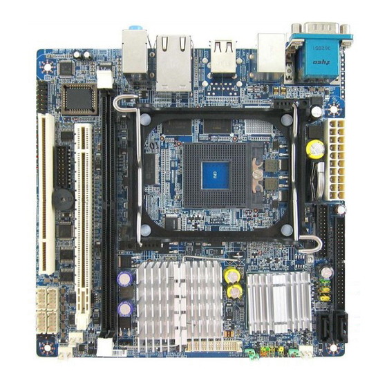
Page 11: Mainboard Layout
MX945GME Mainboard Mainboard Layout MX945GME v2.X Mini ITX Mainboard... -
Page 12: Chapter 2 Hardware Setup
Hardware Setup Chapter 2 Hardware Setup This chapter provides you with the information about hardware setup procedures. While doing the in- stallation, be careful in holding the components and follow the in- stallation procedures. For some components, if you install in the wrong orientation, the components will not work properly. -
Page 13: Quick Components Guide
MX945GME Mainboard Quick Components Guide... -
Page 14: Cpu (Central Processing Unit)
Hardware Setup CPU (Central Processing Unit) ® The mainboard supports Intel Core 2 Duo/Core Duo/Core Solo/Pentium Dual-Core/ ® M processors in Socket M. When you are installing the CPU, make sure the CPU Celeron has a heat sink and a cooling fan attached on the top to prevent overheating. If you do not have the heat sink and cooling fan, contact your dealer to purchase and install them before turning on the computer. -
Page 15: Cpu & Cooler Set Installation
MX945GME Mainboard CPU & Cooler Set Installation 1 . Place the CPU on top of the socket. Make sure to align the gold arrow on the CPU with the arrow key on the socket. 2 . Push the CPU down... - Page 16 Hardware Setup 5 . Mount the cooler set (fan & heatsink bundled) on top of the CPU and fit it into the retention mecha- nism. 7 . Connect power 6 . Secure the metal clips cable from the mounted back to the retention 3-pin mechanism.
-
Page 17: Memory
MX945GME Mainboard Memory The mainboard provides one 240-pin non-ECC DDRII 533/667 DIMM slot and supports up to 2GB system memory. For more information on compatible components, please visit http://www.bcmcom.com. DDRII 240-pin, 1.8V 64x2=128 pin 56x2=112 pin Single-Channel: All DIMMs in GREEN... -
Page 18: Power Supply
Hardware Setup Power Supply ATX 20-Pin System Power Connector: ATX1 This connector allows you to connect to an ATX power supply. To connect to the ATX power supply, make sure the plug of the power supply is inserted in the proper orientation and the pins are aligned. -
Page 19: Back Panel
MX945GME Mainboard Back Panel Serial Port LAN Port Mouse Line-In Line-Out Mic-In VGA Port Keyboard USB Ports LAN Ports Serial Port Connector The serial port is a 16550A high speed communica- tions port that sends/ receives 16 bytes FIFOs. You can attach a serial mouse or other serial devices directly to the connector. -
Page 20: Chassis Intrusion Switch Connector: Jci1
Hardware Setup Connectors Chassis Intrusion Switch Connector: JCI1 This connector connects to a 2-pin chassis switch. If the chassis is opened, the switch will be short. The system will record this status and show a warn- ing message on the screen. To clear the warning, you must enter the BIOS utility and clear the record. -
Page 21: Serial Ata Connectors: Sata1, Sata2
MX945GME Mainboard Serial ATA Connectors: SATA1, SATA2 SATA1~SATA2 are high-speed SATA interface ports and support SATA data rates of 150MB/s. Each SATA con- nector can connect to 1 hard disk device and is fully compliant with Serial ATA 1.0 specifications. -
Page 22: Audio Amplifier Connector: Jamp1
Hardware Setup Audio Amplifier Connector: JAMP1 The JAMP1 is used to connect audio amplifiers to enhance audio performance. Pin Definition SIGNAL JAMP1 AMP_L- AMP_L+ AMP_R- AMP_R+ Front Audio Connector: JAUD1 The JAUD1 connects to an optional audio bracket that provides extra front panel audio IO jacks. -
Page 23: Fan Power Connectors: Cpufan1, Sysfan1
Mainboard Fan Power Connectors: CPUFAN1, SYSFAN1, SYSFAN2 The fan power connectors support system cooling fan with +12V. When connecting the wire to the connectors, always take note that the red wire is the positive and should be connected to the +12V, the black wire is Ground and should be connected to GND. - Page 24 Hardware Setup Serial Port Connector: COM2 – COM5 Each RS232 COM port has similar pinouts. Signal Signal NDCD NSIN NSOUT NDTR NDSR NRTS NCTS VCC_COM [KEY] 2-13...
-
Page 25: Front Usb Connector: F_Usb2
MX945GME Mainboard Front USB Connector: F_USB2 The mainboard provides one USB 2.0 pinheader (op- tional USB 2.0 bracket available) that is compliant with Intel I/O Connectivity Design Guide. USB 2.0 ® technology increases data transfer rate up to a maximum throughput of 480Mbps, which is 40 times faster than USB 1.1, and is ideal for connecting... -
Page 26: Digital Io Connector: J3
Hardware Setup Digital IO Connector: J3 The J3 connects to the General-Purpose Input/Output (GPIO) peripheral module. J3 Pin Definition SIGNAL SIGNAL VCC3 VCC5 N_GPIO10 N_GPIO20 N_GPIO11 N_GPIO21 N_GPIO12 N_GPIO22 N_GPIO13 N_GPIO23 N_GPIO14 N_GPIO24 N_GPIO15 N_GPIO25 N_GPIO16 N_GPIO26 N_GPIO17 N_GPIO27 Parallel Port Header: JLPT1 The mainboard provides a 26-pin header for connec- tion to a parallel port bracket. -
Page 27: Lvds Flat Panel Connector: Jlvds1
MX945GME Mainboard LVDS Flat Panel Connector: JLVDS1 The LVDS (Low Voltage Differential Signal) connec- tor provides a digital interface typically used with flat panels. After connecting an LVDS interfaced flat panel to the JLVDS1, be sure to check the panel... -
Page 28: Jumpers
Hardware Setup Jumpers LVDS Power Selection Jumper: J1 Use this jumper to specify the LVDS power. Signal Name VCC3 LCD_SRC (default VCC3) VCC5 Voltage Select for COM2-COM5: J4 - J7 COM Port Power Jumpers: JCOMP4, JCOMP5 These jumpers specify the operation voltage of the serial ports COM2 – COM5. J4 ->... -
Page 29: Slots
MX945GME Mainboard Slots PCI ( Peripheral Component Interconnect ) Express Slot PCI Express architecture provides a high performance I/O infrastructure for Desktop Platforms with transfer rates starting at 2.5 Giga transfers per second over a PCI Express x1 lane for Gigabit Ethernet, TV Tuners, 1394 controllers, and general pur- pose I/O. -
Page 30: Chapter 3 Bios Setup
BIOS Setup Chapter 3 BIOS Setup This chapter provides information on the BIOS Setup program and allows you to configure the system for optimum use. You may need to run the Setup program when: ² An error message appears on the screen during the system booting up, and requests you to run SETUP. -
Page 31: Entering Setup
BIOS and should be held for reference only. 2 . Upon boot-up, the 1st line appearing after the memory count is the BIOS version. It is usually in the format: MX945GME #70461 BIOS Vx.x... -
Page 32: Control Keys
BIOS Setup Control Keys ↑ > < Move to the previous item ↓ > < Move to the next item ← > < Move to the item in the left hand → > < Move to the item in the right hand <Enter>... -
Page 33: The Menu Bar
MX945GME Mainboard The Menu Bar Main Use this menu for basic system configurations, such as time, date etc. Advanced Use this menu to set up the items of special enhanced features available on your system’s chipset. PC Health This entry monitors your hardware health status. - Page 34 BIOS Setup Main Date (mm:dd:yy) The date format is <Day>, <Month> <Date> <Year>. Time (hh:mm:ss) The time format is <Hour> <Minute> <Second>. IDE Channel 0/1 Master/Slave Press PgUp/<+> or PgDn/<-> to select [Manual], [None] or [Auto] type. Note that the specifications of your drive must match with the drive table.
- Page 35 MX945GME Mainboard Halt On The setting determines whether the system will stop if an error is detected at boot. When the system stops for the errors preset, it will halt on for 15 seconds and then automatically resume its operation. Available options are: [All Errors] The system stops when any error is detected.
-
Page 36: Advanced
BIOS Setup Advanced Advanced BIOS Features The sub-menu is used to configure chipset features for optimal system performance. Quick Power On Self Test Select [Enabled] to reduce the amount of time required to run the power-on self-... - Page 37 MX945GME Mainboard test (POST). A quick POST skips certain steps. We recommend that you nor- mally disable quick POST. Better to find a problem during POST than lose data during your work. Boot Up NumLock Status This setting is to set the Num Lock status when the system is powered on.
- Page 38 BIOS Setup DRAM Timing Selectable Selects whether DRAM timing is controlled by the SPD (Serial Presence Detect) EEPROM on the DRAM module. Setting to [By SPD] enables DRAM timing to be determined automatically by BIOS based on the configurations on the SPD. Selecting [Manual] allows users to configure the following fields manually.
- Page 39 MX945GME Mainboard Use this item to configure the clock frequency of the installed DRAMs. **VGA Setting** The following items allow you to configure the VGA settings of the system. PEG/Onchip VGA Control This setting allows you to select whether to use the onchip graphics processor or the PCI Express card.
- Page 40 BIOS Setup Integrated Peripherals OnChip IDE Device IDE Primary Master/Slave PIO The IDE PIO (Programmed Input/Output) fields let you set a PIO mode for the IDE devices that the onboard IDE interface supports. Modes 0 through 4 provide successively increased performance. In [Auto] mode, the system automatically determines the best mode for each device.
- Page 41 MX945GME Mainboard ME, XP or a third-party IDE bus master driver). If your hard drive and your system software both support Ultra DMA/33, Ultra DMA/66 and Ultra DMA/ 100 , select [Auto] to enable BIOS support. *** On-Chip Serial ATA Setting *** On-Chip Serial ATA This setting specifies the function of the on-chip SATA controller.
- Page 42 BIOS Setup Azalia/AC97 Audio Select Azalia is the codename of “High Definition Audio.” This setting controls the High Definition Audio interface integrated in the Southbridge. Audio Amplifier Control This setting disables/enables the audio amplifier. Amplifier dB When the Audio Amplifier Control is set to [Enabled], users may adjust the amplifier dB range between the lowest useful output and the largest useful output level.
- Page 43 MX945GME Mainboard Serial Port Setting Onboard Serial Port 1 / 2 / 3 / 4 / 5 Select an address for Serial Port 1/2/3/4/5. Serial Port 1 / 2 / 3 / 4 / 5 Use IRQ Select a corresponding interrupt for Serial Port 1/2/3/4/5.
- Page 44 BIOS Setup Power Management Setup ACPI Function This item is to activate the ACPI (Advanced Configuration and Power Man- agement Interface) Function. If your operating system is ACPI-aware, such as Windows 98SE/2000/ME, select [Enabled]. ACPI Suspend Type This item specifies the power saving modes for ACPI function. If your oper- ating system supports ACPI, such as Windows 98SE, Windows ME and Windows 2000, you can choose to enter the Standby mode in S1 (POS) or S3 (STR) fashion through the setting of this field.
- Page 45 MX945GME Mainboard Wake-Up By PCI Card When setting to [Enabled], this setting allows your system to be awakened from the power saving modes through any event on PCI PME (Power Man- agement Event). Power On by Ring An input signal on the serial Ring Indicator (RI) line (in other words, an incoming call on the modem) awakens the system from a soft off state.
-
Page 46: Pc Health
BIOS Setup PC Health Smart Fan Setting 3-17... - Page 47 MX945GME Mainboard Smart System / CPU Fan Temp. Select a temperature setting here, and if the temperature of the CPU/system climbs up to the selected temperature setting, the system will automatically increase the speed of the CPU/system fan to cool down the overheated CPU/ system.
-
Page 48: Security
BIOS Setup Security Set Supervisor Password Supervisor Password controls access to the BIOS Setup utility. Set User Password User Password controls access to the system at boot. Security Option This specifies the type of BIOS password protection that is implemented. Settings are described below: Option Description... -
Page 49: System
MX945GME Mainboard System Machine Type/Model, Processor, Processor Cache Size, Processor Speed, System Memory Type, Video Controller, BIOS Date, BIOS Version These items show the hardware specifications of your system. Read only. 3-20... -
Page 50: Boot
BIOS Setup Boot Hard Disk Boot Priority This setting allows users to set the boot priority of the specified hard disk devices. First press <Enter> to enter the sub-menu. Then you may use the arrow keys ( -¯ ) to select the desired device, then press <+>, <-> or <PageUp>, <PageDown> key to move it up/down in the priority list. -
Page 51: Exit
MX945GME Mainboard Exit Load Fail-Safe Defaults Use this menu to load the default values set by the BIOS vendor for stable system performance. Load Optimized Defaults Use this menu to load the default values set by the mainboard manufacturer specifi- cally for optimal performance of the mainboard.
Need help?
Do you have a question about the MX945GME and is the answer not in the manual?
Questions and answers