
Related Manuals for BCM MX610HD


Summary of Contents for BCM MX610HD
- Page 1 MX610HD Intel® H610E support 12 generation Core™ i9, Core i7, Core i5, Core i3, Pentium, Celeron Mini-ITX Motherboard User’s Manual Ver. 1.0...
-
Page 2: Table Of Contents
1.6.6 eDP voltage selection (EDPPWR1) ....................... 32 1.7 Connectors........................32 1.7.1 Rear panel connectors ........................... 32 1.7.2 CPU and System fan connectors (CPU_FAN1, CHA_FAN1)..............33 1.7.3 System Panel (F_PANEL) ........................34 1.7.4 ATX power connectors (ATX12V1) ......................35 2 MX610HD User’s Manual... - Page 3 2.4.9.1 Console Redirection settings ........................... 60 2.4.10 intel TXT information ..........................62 2.4.11 USB configuration ..........................62 2.4.12 Network Stack Configuration ........................ 64 2.4.13 IP configuration ............................ 65 2.4.14 NVMe Configuration ..........................66 2.4.15 Remote Server Configuration ....................... 67 MX610HD User’s Manual 3...
- Page 4 2.5.2.2 SATA Configuration ............................78 2.5.2.3 USB Configuration ............................79 2.5.2.4 HD audio Configuration ..........................80 2.5.2.5 Serial IO Configuration ........................... 81 2.6 Security ........................... 82 2.7 Boot ..........................83 2.8 Save & Exit ........................84 4 MX610HD User’s Manual...
-
Page 5: Safety Information
If you encounter technical problems with the product, contact a qualified service technician or your retailer. The symbol of the crossed out wheeled bin indicates that the product (electrical and electronic equipment) should not be placed in municipal waste. Check local regulations for disposal of electronic products. MX610HD User’s Manual 5... - Page 6 This device complies with the requirements in Part 15 of the FCC rules. Operation is subject to the following two conditions: This device may not cause harmful interference. This device must accept any interference received, including interference that may cause undesired operation. 6 MX610HD User’s Manual...
-
Page 7: About This Guide
CAUTION: Information to prevent damage to the components when trying to complete a task. IMPORTANT: Instructions that you MUST follow to complete a task. NOTE: Tips and additional information to help you complete a task. MX610HD User’s Manual 7... -
Page 8: Typography
Example: <Ctrl>+<Alt>+<D> Command Means that you must type the command exactly as shown, then supply the required item or value enclosed in brackets Example: At the DOS prompt, type the command line: afudos /i[filename] afudos /iP5P800VM.ROM 8 MX610HD User’s Manual... -
Page 9: Packing List
MX610HD User’s Manual Packing List Before you begin installing your single board, please make sure that the following materials have been shipped: 1 x mini-ITX MX610HD Main board 2 x I/O Shield (Full Size I/O Shield+ Half Size I/O Shield) ... -
Page 10: Revision History
MX610HD User’s Manual Revision History Revision Revision History Date V 0.1 First release version Aug, 2022 V 1.0 Production release version Nov, 2022 10 MX610HD User’s Manual... -
Page 11: Chapter 1 - Product Introduction
MX610HD User’s Manual This chapter describes the motherboard features and the new technologies it supports. Product Introduction MX610HD User’s Manual 11... -
Page 12: Specifications Summary
2 x RS-232/422/485 Headers with Voltage Selection (2.0mm Pitch) Internal I/O 1 x USB 2.0 Headers with Shroud (2 Ports on Header) 1 x USB 3.2 Gen 1 Header with Shroud (2 Ports on Header) 1 x LVDS Header 1 x eDP Header (Optional) 12 MX610HD User’s Manual... - Page 13 1 x Chassis Intrusion Locking Type Header 1 x 4 Pin Mini-Fit Jr DC-In Header Mechanical & Environmental Operating Temperature 0~60°C (32~140°F) Operating Humidity 5%~90% relative humidity, non-condensing Size (L x W) 6.7" (L) x 6.7" (W) (170mm x 170mm) MX610HD User’s Manual 13...
- Page 14 MX610HD User’s Manual Block Diagram 14 MX610HD User’s Manual...
-
Page 15: Before You Proceed
The edge with external ports goes to the rear part of the chassis as indicated in the image below. 1.2.2 Screw Holes Place four screws into the holes indicated by circles to secure the motherboard to the chassis. Do not over tighten the screws! Doing so can damage the motherboard. MX610HD User’s Manual 15... - Page 16 MX610HD User’s Manual Place this side towards the rear of the chassis. 16 MX610HD User’s Manual...
-
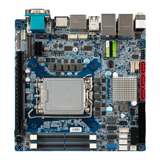
Page 17: Motherboard Layout
M.2 key E slot PCIEx1+USB interface M2M_1 M.2 key M slot PCIEx4+SATA interface Jumpers Label Function Note CLCMOS1 Clear CMOS 1 x 3 header, pitch 2.00mm JPSON1 AT/ATX Mode setting 1 x 3 header, pitch 2.00mm MX610HD User’s Manual 17... - Page 18 BOX header 2x5P, 2.54mm LVDS1 LVDS header WAFER 2x20P, 1.25mm JBKL1 LVDS backlight connector WAFER 1x5P, 2.0mm SMBUS1 SMBus connector WAFER 1x5P, 2.0mm JAMP1 Amplifier Connector WAFER 1x4P, 2.0mm JCASE1 Chassis Intrusion Header WAFER 1x2P, 2.5mm 18 MX610HD User’s Manual...
-
Page 19: Central Processing Unit (Cpu)
Contact your retailer immediately if the PnP cap is missing, or if you see any damage to the PnP cap/socket pins/motherboard components. BCM will shoulder the cost of repair only if the damage is shipment/transit-related. ... - Page 20 To prevent damage to the socket pins, do not remove the PnP cap unless you are installing a CPU. 3. Lift the Load lever with your thumb and forefinger to around 120º angle (C), then pull the PnP cap from the CPU socket to remove (D). 20 MX610HD User’s Manual...
- Page 21 CPU notch. Keying Features Processor Corners 4x 5. Pull back the load lever, then push the load lever (E) until it snaps into the retention tab. MX610HD User’s Manual 21...
-
Page 22: Installing The Cpu Heatsink And Fan
CPU. Making sure that the four fasteners match the holes on the motherboard. Fasten the screws Fastener Motherboard hole Orient the heatsink and fan assembly such that the CPU fan cable is closest to the CPU fan connector. 22 MX610HD User’s Manual... -
Page 23: Uninstalling The Cpu Heatsink And Fan
These are not jumpers! DO NOT place jumper caps on the fan connectors. 1.3.3 Uninstalling the CPU Heatsink and Fan To uninstall the CPU heatsink and fan: 1. Disconnect the CPU fan cable from the connector on the motherboard. MX610HD User’s Manual 23... - Page 24 2. Rotate each fastener counterclockwise 3. Pull up two fasteners at a time in a diagonal sequence to disengage the heatsink and fan assembly from the motherboard. 4. Carefully remove the heatsink and fan assembly from the motherboard. 24 MX610HD User’s Manual...
-
Page 25: System Memory
The DDR5 specification is bringing the maximum potential capacity for a single DDR5 DIMM to 128GB, a theoretical maximum transfer speed of 6400MT/s which is doubling the rate of DDR4, along with the improved power consumption as 1.1V. 262-Pin DDR5 SODIMM sockets MX610HD User’s Manual 25... -
Page 26: Installing A Sodimm
2. Pull the SODIMM down and away from the holder to remove it. Support the DIMM lightly with your fingers when releasing the locking arms. The DIMM might get damaged when it flips out with extra force. 26 MX610HD User’s Manual... -
Page 27: Expansion Card
2. Assign an IRQ to the card if needed. Refer to the tables on the next page. 3. Install the software drivers for the expansion card. 1.5.3 PCI Express x16 slot This motherboard supports 1 PCI Express x16 slot that complies with the PCI Express specifications. MX610HD User’s Manual 27... -
Page 28: Connector
Support PCIe, SATA and USB interface of this connector. 1x M.2 2242/2280/22110 M Key NVMe (PCIe x4 + SATA III) 1 x M.2 2230 E Key with CNVi Support (PCIe x 1 + USB 2.0) M.2 E key M.2 M key 28 MX610HD User’s Manual... -
Page 29: Jumpers
Except when clearing the RTC RAM, never remove the cap on CLRTC jumper default position. Removing the cap will cause system boot failure! Normal (Default) Clear CMOS 1.6.2 AT/ATX Power Mode Select (JPSON1) This jumper allows you to select ATX Mode or AT mode MX610HD User’s Manual 29... -
Page 30: Com Power Setting (Jcompwr1~3)
MX610HD User’s Manual AT mode ATX mode (Default) 1.6.3 COM POWER SETTING (JCOMPWR1~3) This jumper allows you to select COM1~6 to support Ring/+12V/+5V Ring +12V 30 MX610HD User’s Manual... -
Page 31: Lvds Backlight Voltage Selection (Jbklvol)
1.6.4 LVDS backlight voltage selection (JBKLVOL) This jumper allows you to select 3V or 5V for LVDS backlight 1.6.5 LVDS brightness control mode selection (JLVDS_BKL1) This jumper allows you to select control mode for LVDS backlight PWM mode DC mode MX610HD User’s Manual 31... -
Page 32: Edp Voltage Selection (Edppwr1)
HDMI Port The HDMI port Connector LAN1 Gigabit LAN This port allows Gigabit connection to a Local (RJ-45) Area Network (LAN) through a network hub. Connectors Refer to the table below for the LAN port LED indications. 32 MX610HD User’s Manual... -
Page 33: Cpu And System Fan Connectors (Cpu_Fan1, Cha_Fan1)
1A~2.22A (26.64W max.) at +12V. Connect the fan cables to the fan connectors on the motherboard, making sure that the black wire of each cable matches the ground pin of the connector. MX610HD User’s Manual 33... -
Page 34: System Panel (F_Panel)
BIOS settings. Pressing the power switch and holding it for more than four seconds while the system is ON turns the system OFF. 34 MX610HD User’s Manual... -
Page 35: Atx Power Connectors (Atx12V1)
Make sure that your power supply unit (PSU) can provide at least the minimum power required by your system. See the table below for details. MX610HD User’s Manual 35... -
Page 36: Serial Port Connectors (Com1~3)
1.7.6 Serial ATA Connector (SATA1~2 ) SATA 1~4 support SATA III. These connectors are suitable for the SATA signal cables and connect to Serial ATA devices. SATA 1. GND 2. TX+ 3. TX- 4. GND 5. RX- 6. RX+ 7. GND 36 MX610HD User’s Manual... -
Page 37: Usb Connectors (Usb78)
This connector provides 2 USB3.2 Gen1 ports. Connect the optional USB module cable to any of these connectors, then install the module to a slot opening at the back of the system chassis. These USB connectors comply with USB3.2 specification that supports up to 5Gbps connection speed. MX610HD User’s Manual 37... -
Page 38: Bit Gpio Header (Jdio1)
This connector provides a 8 bits input or output for general purpose. 1. SIO_GPIO0 2. SIO_GPIO4 3. SIO_GPIO1 4. SIO_GPIO5 5. SIO_GPIO2 6. SIO_GPIO6 7. SIO_GPIO3 8. SIO_GPIO7 9. SMB_CLK_ 10. SMB_DATA_ RESUME RESUME 11. GND 12. +5Vsb 38 MX610HD User’s Manual... -
Page 39: Front Audio Connector (Fp_Audio1)
8. NC 5. LINE2R 6. MIC2-JD 4. +3.3 3. MIC2R 2. GND 1. MIC2L 1.7.11 Amplifier Connector (JAMP1) This connector allow user to connect an external audio amplifier. JAMP1 1. AMP_L- 2. AMP_L+ 3. AMP_R- 4. AMP_R+ MX610HD User’s Manual 39... -
Page 40: Sm Bus Connector (Smb1)
MX610HD User’s Manual 1.7.12 SM bus connector (SMB1) 5. 3.3V 4. GND 3. SMB_ALT 2. SMB_DATA 1. SMB_CLK 1.7.13 I2C connector (I2C1) 4. GND 3. I2C_SDA 2. I2C_SCL 1. +3.3V 40 MX610HD User’s Manual... -
Page 41: Chassis Intrusion Connector (Jcase1)
17. LVDS_A3- 18. LVDS_A2- 15. LVDS_A3+ 16. LVDS_A2+ 13. GND 14. GND 11. LVDS_A1- 12. LVDS_A0- 9. LVDS_A1+ 10. LVDS_A0+ 7. GND 8. GND 5. DDC_CLK 6. DDC_DATA 3. VDD_+3.3V 4. VDD_+5V 1. VDD_+3.3V 2. VDD_+5V MX610HD User’s Manual 41... - Page 42 MX610HD User’s Manual This chapter tells how to change the system settings through the BIOS Setup menus. Detailed descriptions of the BIOS parameters are also provided. BIOS Step 42 MX610HD User’s Manual...
-
Page 43: Chapter 2 - Bios Setup
The BIOS setup screens shown in this section are for reference purposes only, and may not exactly match what you see on your screen. Visit the system builder’s website to download the latest BIOS file for this motherboard MX610HD User’s Manual 43... -
Page 44: Legend Box
<F3> to load the optimal default values. While moving around through the Setup program, note that explanations appear in the Item Specific Help window located to the right of each menu. This window displays the help text for the currently highlighted field. 44 MX610HD User’s Manual... -
Page 45: Bios Menu Screen
To access the menu items, press the up/down/right/left arrow key on the keyboard until the desired item is highlighted, then press [Enter] to open the specific menu. MX610HD User’s Manual 45... -
Page 46: Main Setup
Use this menu for basic system configurations, such as time, date etc. BIOS Information Displays the auto-detected BIOS information. System Date The date format is <Date>,<Month>,<Day>,<Year>. System Time The time format is <Hour>,<Minute>,<Second>. 46 MX610HD User’s Manual... -
Page 47: Advanced Bios Setup
The Advanced BIOS Setup screen is shown below. The sub menus are described on the following pages. Take caution when changing the settings of the Advanced menu items. Incorrect field values can cause the system to malfunction. MX610HD User’s Manual 47... -
Page 48: Cpu Configuration
When enabled, a VMX can utilize the additional hardware compatibilities provided by Vandorpool Technology Configuration options: [Enable] [Disable] Active Performance –Cores Number of P-core to enable in each processor package Hyper-Threading Enable or disable Hyper-Threading technology Configuration options: [Enable] [Disable] 48 MX610HD User’s Manual... -
Page 49: Power & Performance
When enabled, CPU will switch to minimum speed when all cores enter C state Configuration options: [Enable] [Disable] Package C state limit Maximum package C state limit setting. CPU default : Leaves to factory default value Configuration options: [C0/C1] [C2] [C3] MX610HD User’s Manual 49... -
Page 50: Pch-Fw Configuration
ME State [Enabled] When disabled ME will be put into ME temporarily disabled mode Configuration options: [Enable] [Disable] ME unlock control [Lock] When Set unlock, system will shut down for active function Configuration options: [Lock] [Unlock] 50 MX610HD User’s Manual... -
Page 51: Trusted Computing
MX610HD User’s Manual 2.4.4 Trusted Computing Security device settings TPM Device Selection [dTPM] Select TPM device Configuration options: [dTPM] [PTT] Security Device support [Disabled] Enable or Disable BIOS support security device Configuration options: [Enable] [Disable] MX610HD User’s Manual 51... -
Page 52: Acpi Settings
PCIE# wake from S5 [Disabled] Enable or disable PCIE wake the system from S5. Configuration options: [Disabled] [Enabled] Wake on Ring [Disabled] Enable or disable wake on ring function under ACPI S3/S4/S5. Configuration options: [Disabled] [Enabled] 52 MX610HD User’s Manual... -
Page 53: Nct6126D Super Io Configuration
Configuration options: [Second] [Minute] WatchDog Timeout value Fill watchdog timeout value, 0 means disables Chassis opened warning [Disabled] Select chassis intrusion enabled to Disabled Configuration options: [Disabled] [Enabled] ErP/EuP S5 Support [Disabled] Configuration options: [Disabled] [Enabled] MX610HD User’s Manual 53... -
Page 54: Serial Port 1 Configuration
Configuration options: [Disabled] [Enabled] Change Setting [Auto] Select an optimal settings for super IO device Configuration options: as below COM mode Select [RS232] Configure the COM port Mode Configuration options: [RS232] [RS485 Half Duplex][RS422 Ful Duplex] 54 MX610HD User’s Manual... -
Page 55: Serial Port 2 Configuration
Configuration options: [RS232] [RS485 Half Duplex][RS422 Ful Duplex] 2.4.6.3 Serial Port 3 Configuration Serial Port [Enabled] Enable or Disable serial Port (COM) Configuration options: [Disabled] [Enabled] Change Settings [Auto] Select an optimal settings for super IO device Configuration options: as below MX610HD User’s Manual 55... -
Page 56: Hardware Monitor
MX610HD User’s Manual 2.4.7 Hardware monitor Display Hardware monitor information 56 MX610HD User’s Manual... -
Page 57: Smart Fan
MX610HD User’s Manual 2.4.7.1 Smart FAN Smart FAN Function [Enabled] Smart fan function Enable/Disabled Configuration options: [Enabled] [Disabled][Manual] 2.4.7.1.1 Smart FAN mode Configuration Setting different FAN on this motherboard MX610HD User’s Manual 57... - Page 58 MX610HD User’s Manual CPU_FAN1/CHA_FAN1 FAN Target Smart FAN target temperature Configuration options: Please see below picture CPU_FAN1/CHA_FAN1 MIN.FAN Speed (%) CPU or Chassis Smart FAN minimum settings Configuration options: Please see below picture 58 MX610HD User’s Manual...
-
Page 59: S5 Rtc Wake Settings
MX610HD User’s Manual 2.4.8 S5 RTC wake settings Wake system from S5 [Disabled] MX610HD User’s Manual 59... -
Page 60: Serial Port Console Redirection
Enabled or Disabled system wake on alarm event Configuration options: [Enabled] [Disabled] 2.4.9 Serial Port Console Redirection Display CPU configuration Console Redirection [Disabled] Enabled or Disabled COM1 Console redirection Configuration options: [Disabled][Enabled] 2.4.9.1 Console Redirection settings 60 MX610HD User’s Manual... - Page 61 Stop Bits[1] Stop bits indicate the end of a serial data package Configuration options: [1][2] Flow Control[None] Flow control can prevent data loss from buffer overflow. Configuration options: [None][Hardware RTS/CTS] VT-UTF8 Combo key Support [Enabled] MX610HD User’s Manual 61...
-
Page 62: Intel Txt Information
Enables or disables extended terminal resolution Configuration options: [Enabled] [Disabled] Putty Keypad [VT100] Selects function key and keypad on putty Configuration options: [VT1000] [LINUX][XTERMR6][SCO][ESCN][VT400] 2.4.10 intel TXT information Display Intel TXT information. This depends on CPU sku. 2.4.11 USB configuration 62 MX610HD User’s Manual... - Page 63 USB Mass Storage Driver Support [Enabled] Enable or Disable USB Mass Storage Driver Support Configuration options: [Enabled][Disabled] Mass Storage Devices [Auto] Mass Storage device emulation Type. “Auto” enumerates device according to its media format. MX610HD User’s Manual 63...
-
Page 64: Network Stack Configuration
Enabled or disabled IPv6 PXE boot Support Configuration options: [Enabled][Disabled] PXE boot wait time Wait time in seconds to press ESC key to abort the PXE boot. Media detect count Number of time the presence of media will be checked 64 MX610HD User’s Manual... -
Page 65: Ip Configuration
MX610HD User’s Manual 2.4.13 IP configuration Auto Configuration[Disabled] Allow user to set IP. DisabledIP won’t set Every BootSets IP on every boot On demandUser has to set IP using IPConfig interface. MX610HD User’s Manual 65... -
Page 66: Nvme Configuration
MX610HD User’s Manual 2.4.14 NVMe Configuration Display NVMe controller or Drive information 66 MX610HD User’s Manual... -
Page 67: Remote Server Configuration
Need to do clear Enrollment, if server is changed to DHCP. Configuration options: [Enabled][Disabled] Server Address [Enabled] Management server address to be used if Auto server searching is either disabled or failed. If changed, need to do clear Enrollment if already enrolled with previous IP. MX610HD User’s Manual 67... -
Page 68: Chipset
MX610HD User’s Manual 2.5 Chipset 68 MX610HD User’s Manual... -
Page 69: System Agent (Sa) Configuration
2.5.1 System Agent (SA) Configuration VT-d [Enabled] VT-d capability Configuration options: [Disabled] [Enabled] 2.5.1.1 Memory Configuration Maximum Value of TOLUD. Dynamic assignment would adjust TOLUD automatically based on largest MMIO length of installed graphic controller. MX610HD User’s Manual 69... -
Page 70: Graphic Configuration
Primary Display[Auto] Select which of IGFX/PEG/PCIE graphic device should be primary display or select HG for Hybrid Gfx. Configuration options: [Auto] [IGFX][PEG slot][PCIE] Internal Graphics [Auto] Keep IGFX enabled based on the setup options 70 MX610HD User’s Manual... -
Page 71: Lcd Control
Configuration options: [Auto] [disabled][enabled] PSMI Support [Disabled] PSMI enabled/Disabled Configuration options: [Disabled][Enabled] DVMT Pre-allocated [60M] Select DVMT 5.0 Pre-allocated (Fixed) Graphics memory size used by the internal graphics device. Configuration options: As below picture 2.5.1.2.1 LCD Control MX610HD User’s Manual 71... -
Page 72: Pci Express Configuration
Enable/Disable LCD. LCD is LVDS or eDP panel Configuration options: [Disabled][Enabled] 2.5.1.3 PCI Express Configuration Detect Non-compliance Device [Disabled] Detect Non-compliance Device in PEG Configuration options: [Disabled][Enabled] 2.5.1.3.1 PCI Express Root Port 2 (x16 PEG slot) 72 MX610HD User’s Manual... - Page 73 PCI Express Root Port 2[Enabled] Control the PCI express Root Port Configuration options: [Enabled] [Disabled] ASPM [Disabled] Set the ASPM level Configuration options: [Disaled] [L0s][L1][L0sL1] PCIe Speed [Auto] Configure PCIe Speed Configuration options: [Auto][Gen1][Gen2][Gen3][Gen4][Gen5] MX610HD User’s Manual 73...
-
Page 74: Pch-Io Configuration
Enabled or Disabled boot option for LAN2 controller Configuration options: [Disabled][Enabled] Restore AC Power Loss[Power off] Specify what state to go to when power is re-applied after a power failure Configuration options: [Power on][Power off][Last State] 74 MX610HD User’s Manual... -
Page 75: Pci Express Configuration
Enabled Flash Protection Range Registers Configuration options: [Disabled][Enabled] GPIO Group Control [Disabled] Configure the digital GPIO pins Configuration options: [Disabled][Enabled] Amplifier GAIN(db) [15.3db] Select Amplifier GAIN value Configuration options: [15.3db][21.2db][27.2db][31.8db] 2.5.2.1 PCI Express Configuration MX610HD User’s Manual 75... -
Page 76: Pci Express Root Port 1(X1 Keye)
PCIe Speed [Auto] Select PCI Express Port speed Configuration options: [Auto][Gen1][Gen2][Gen3] [Gen4] Detect Non-compliance device [Disabled] Detect non-compliance PCI express Device, If enabled, it will take more time at Post time. Configuration options: [Disabled][Enabled] 76 MX610HD User’s Manual... -
Page 77: Pci Express Root Port 5(X4 Key M)
PCIe Speed [Auto] Select PCI Express Port speed Configuration options: [Auto][Gen1][Gen2][Gen3] [Gen4] Detect Non-compliance device [Disabled] Detect non-compliance PCI express Device, If enabled, it will take more time at Post time. Configuration options: [Disabled][Enabled] MX610HD User’s Manual 77... -
Page 78: Sata Configuration
Enable or Disable SATA port 2 Configuration options: [Enable ][Disabled] Port 3 [Enabled] Enable or Disable SATA port 3 Configuration options: [Enabled][Disabled] M2 port [Enabled] Enable or Disable SATA on M.2 Key M slot Configuration options: [Enabled][Disabled] 78 MX610HD User’s Manual... -
Page 79: Usb Configuration
Enable or Disable USB standby power Configuration options: [Disabled] [Enabled] USB56 Standby Power[Enabled] Enable or Disable USB standby power Configuration options: [Disabled] [Enabled] USB78 Standby Power[Enabled] Enable or Disable USB standby power Configuration options: [Disabled] [Enabled] MX610HD User’s Manual 79... -
Page 80: Hd Audio Configuration
MX610HD User’s Manual 2.5.2.4 HD audio Configuration HD audio[Enabled] Control Detection of the HD-Audio device. Configuration options: [Disabled] [Enabled] 80 MX610HD User’s Manual... -
Page 81: Serial Io Configuration
MX610HD User’s Manual 2.5.2.5 Serial IO Configuration I2C0 Controller[Enabled] Enabled/Disabled Serial IO Controller Configuration options: [Disabled] [Enabled] I2C2 Controller[Enabled] Enabled/Disabled Serial IO Controller Configuration options: [Disabled] [Enabled] MX610HD User’s Manual 81... -
Page 82: Security
MX610HD User’s Manual 2.6 Security Administrator Password Set Administrator Password User Password Set User Password 82 MX610HD User’s Manual... -
Page 83: Boot
Configuration options: [LEGACY] [UEFI] UEFI USB Key Drive BBS Priorities Specifies the boot device priority sequence from available UEFI USB key Drives. UEFI Application Boot Priorities Specifies the boot device priority sequence from available UEFI Application. MX610HD User’s Manual 83... -
Page 84: Save & Exit
Reset the system after saving the changes. Restore Defaults Restore/Load default values for all the setup option. Launch EFI Shell from filesystem device Attempts to launch EFI shell application from one of the available filesystem devices. AMIFWUpdate Launches AMIFWUpdate 84 MX610HD User’s Manual...
Need help?
Do you have a question about the MX610HD and is the answer not in the manual?
Questions and answers