Emerson Smart Wireless Gateway 1410 Reference Manual
Emerson smart wireless gateway 1410
Hide thumbs
Also See for Smart Wireless Gateway 1410:
- Quick start manual (20 pages) ,
- Reference manual (66 pages) ,
- Reference manual (68 pages)

Related Manuals for Emerson Smart Wireless Gateway 1410


Summary of Contents for Emerson Smart Wireless Gateway 1410
- Page 1 Reference Manual 00809-0200-4410, Rev BA February 2014 Emerson Smart Wireless Gateway 1410...
- Page 3 For information on Rosemount nuclear-qualified products, contact your local Emerson Process Management Sales Representative. PlantWeb is a registered trademark of one of the Emerson Process Management group of companies. Modbus is a registered trademark of Schneider Automation, Inc. All other marks are the property of their respective owners.
-
Page 5: Table Of Contents
Reference Manual Table of Contents 00809-0200-4410, Rev BA February 2014 Contents 1Section 1: Overview Safety messages ............1 Introduction . - Page 6 Table of Contents Reference Manual February 2014 00809-0200-4410, Rev BA 4Section 4: Software setup Overview .............27 System requirements .
- Page 7 Reference Manual Table of Contents 00809-0200-4410, Rev BA February 2014 BAppendix B: Product Certifications Approved Manufacturing Locations ........63 Telecommunications Compliance .
-
Page 9: Safety Messages
The 1410 enclosure is engineered polymer. Use care in handling and cleaning when in explosive environments to avoid an electrostatic discharge. Warning - Explosion Hazard Do not make or break any connections to the 1410 while circuits are live unless area is known to be non-hazardous. Overview... -
Page 10: Introduction
00809-0200-4410, Rev BA February 2014 Introduction The Emerson Smart Wireless Gateway 1410 (Gateway) connects WirelessHART™ self-organiz- ing networks with host systems and data applications. Modbus communications over RS-485 or Ethernet provide universal integration and system interoperability. The optional OPC or EtherNet/IP functionality from the Gateway offers a means to connect to newer systems and applications while providing a richer set of data. -
Page 11: Service Support
Reference Manual Section 1: Overview 00809-0200-4410, Rev BA February 2014 Section 3: Mounting and connection This section describes how to properly mount the Gateway and make electrical connections, including electrical wiring, grounding, and host system connections. This section also describes how to mount the optional remote antenna. -
Page 12: Return Of Materials
00809-0200-4410, Rev BA February 2014 Return of materials To expedite the return process outside of North America, contact your Emerson Process Management representative. Within the United States, call the Emerson Process Management Response Center toll-free number 1 800 654 7768. The center, which is available 24 hours a day, will assist you with any needed information or materials. -
Page 13: 2Section 2: Initial Connection
Verify that the operating atmosphere of the gateway is consistent with the appropriate hazardous locations certifications Do not make or break connections to the 1410 while circuits are live unless the area is know to be non-hazardous Potential electrostatic charging hazard. Enclosure is a polymer, use care when handling ... -
Page 14: System Requirements
Reference Manual Section 2: Initial Connection 00809-0200-4410, Rev BA February 2014 System requirements The following requirements apply to the PC/Laptop used to configure the Gateway. Additional requirements may apply if using the Security Setup Utility or AMS Wireless Configurator. See Section 4: Software setup page 27 for more information. -
Page 15: Connections And Power
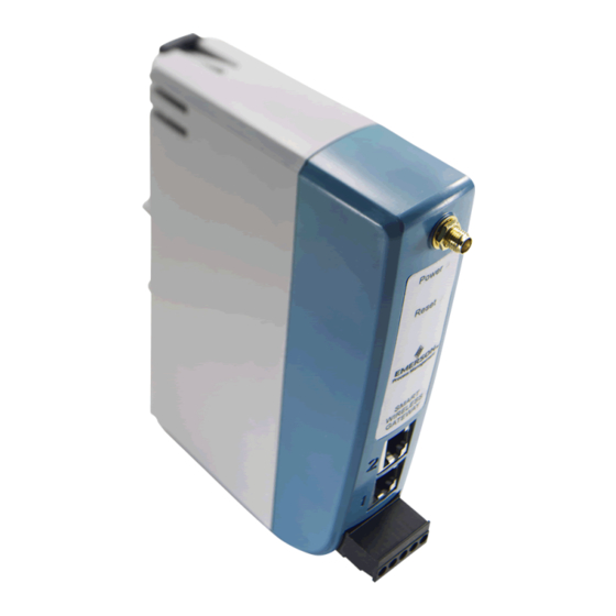
Reference Manual Section 2: Initial Connection 00809-0200-4410, Rev BA February 2014 Internet proxies will need to be disabled through the PC/Laptop’s default internet browser. Disable the proxies with the following procedure: Find and open the default internet browser. Find the Tools menu and select Internet Options. From the Connections tab, click the LAN Settings button. - Page 16 Reference Manual Section 2: Initial Connection 00809-0200-4410, Rev BA February 2014 Figure 2-1. Emerson Smart Wireless Gateway 1410 Housing Diagram Power Reset 24 VDC (nominal) Serial Power Input Modbus A. DIN rail clip. B. SMA connector. C. Power and Reset indicator lights. During normal operation the power indicator will be green. During a reset the reset light will turn red.
-
Page 17: Configure The Gateway
Reference Manual Section 2: Initial Connection 00809-0200-4410, Rev BA February 2014 2.3.3 Configure the gateway It is now possible to log into the Gateway for the first time and begin configuration for placement on a live control network. The following items need to be configured: Security Passwords ... - Page 18 Antivirus and other software tools are not included in the Gateway firmware. These software tools should be installed on any machine connected to the Gateway. Emerson bundles the latest software patches into our standard Gateway firmware updates. These software patches are not anti-malware or antivirus tools in any sense of the word, but do provide the latest in security protection.
-
Page 19: Time Settings
Reference Manual Section 2: Initial Connection 00809-0200-4410, Rev BA February 2014 Logging The Gateway monitors many security events automatically. A complete list of events can be viewed from the Log Settings (Setup>Log Settings) area in the Gateway interface. The Gateway also supports the optional use of a Syslog server. - Page 20 Reference Manual Section 2: Initial Connection 00809-0200-4410, Rev BA February 2014 Figure 2-2. Setup>Time Settings TCP/IP network settings Use caution when making changes to the TCP/IP network settings. If they are lost or entered incorrectly, the Gateway will require a factory reset (see“Resetting to factory defaults”...
- Page 21 Reference Manual Section 2: Initial Connection 00809-0200-4410, Rev BA February 2014 Request the following configuration items from the network administrator: Hostname Domain Name IP address Netmask Gateway Obtaining an IP address from a DHCP server is not recommended, since the Gateway operation will be dependent on the availability of the DHCP server.
-
Page 22: System Backup
Reference Manual Section 2: Initial Connection 00809-0200-4410, Rev BA February 2014 2.3.4 System backup The Gateway has a System Backup and Restore feature that saves all user-configured data. It is best practice that a System Backup be performed periodically throughout the installation and configuration process. -
Page 23: Resetting To Factory Defaults
Reference Manual Section 2: Initial Connection 00809-0200-4410, Rev BA February 2014 2.3.6 Resetting to factory defaults In the event that the user name, password, or IP address of the Gateway is lost, the Gateway can be restored to factory defaults by the procedure below. Note Following this procedure will cause the network to reform and all configuration parameters will be reset to factory defaults. -
Page 25: 3Section 3: Mounting And Connection
Reference Manual Section 3: Mounting and connection 00809-0200-4410, Rev BA February 2014 Section 3 Mounting and connection Overview ..............page 17 Mounting . -
Page 26: Physical Description
Reference Manual Section 3: Mounting and connection 00809-0200-4410, Rev BA February 2014 3.1.2 Physical description The Gateway electronics is enclosed in a polymer housing. The front of the enclosure has connections for power, Ethernet, and serial communications. The unit is designed to be mounted on a DIN rail inside an electronic enclosure. - Page 27 Reference Manual Section 3: Mounting and connection 00809-0200-4410, Rev BA February 2014 To remove the unit, see Figure 3-2. Place a flat or rounded object (such as a screw driver) into the DIN clip and apply a slight pressure downwards on the object. Once the unit is released from the DIN rail pull backwards and down to successfully disengage.
-
Page 28: Remote Antenna
To maintain wireless performance and avoid non-compliance with spectrum regulations, do not change the length of cable or the antenna type. If the supplied remote mount antenna kit is not installed per these instructions, Emerson Process Management is not responsible for wireless performance or non-compliance with spectrum regulations. - Page 29 Reference Manual Section 3: Mounting and connection 00809-0200-4410, Rev BA February 2014 Any spare lengths of coaxial cable should be placed in 1 foot (0,3 m) coils. Figure 3-3. Installation of WL2/WN2 Option Note: Weather proofing is required! The remote mount antenna kit includes coaxial sealant for the cable connections for the lightning arrestor, antenna, and Gateway.
-
Page 30: Connections
Reference Manual Section 3: Mounting and connection 00809-0200-4410, Rev BA February 2014 Connections 3.4.1 Grounding The DIN rail should always be grounded in accordance with national and local electrical codes. The most effective grounding method is a direct connection to earth ground with minimal impedance. -
Page 31: Rs-485
Reference Manual Section 3: Mounting and connection 00809-0200-4410, Rev BA February 2014 Figure 3-5. Emerson Smart Wireless Gateway 1410 Terminal Block Diagram Power Reset 24 VDC (nominal) Serial Power Input Modbus A. 5 screw terminal block. Ethernet connections should use Cat5e shielded cable to connect to an Ethernet hub, switch, or router. -
Page 32: Terminating Resistors
Reference Manual Section 3: Mounting and connection 00809-0200-4410, Rev BA February 2014 Figure 3-6. Convert from Full to Half Duplex 3.4.4 Terminating resistors Three DIP switches are provided to enable various terminating resistors to the RS-485 data bus. The switches are found inside the electronics housing, located behind an access slot on the upper right side. -
Page 33: Power
Reference Manual Section 3: Mounting and connection 00809-0200-4410, Rev BA February 2014 Figure 3-8. Typical Half Duplex (2-wire) Network Up to 4000 ft. (1220 m) Device 2 Device 1 Terminators required only for high data rates Device N and long cable runs (up to 32 possible) 3.4.5... -
Page 35: Overview
Reference Manual Section 4: Software Setup 00809-0200-4410, Rev BA February 2014 Section 4 Software setup Overview ..............page 27 System requirements . -
Page 36: System Requirements
Reference Manual Section 4: Software Setup 00809-0200-4410, Rev BA February 2014 System requirements Table 4-2. PC Hardware Minimum requirements Recommended requirements Intel Core 2 Duo, 2.0 GHz Intel Core 2 Quad, 2.0 GHz or greater 1 GB Memory 3 GB Memory or Greater 1.5 GB free hard disk space 2 GB or more of free hard disk space Note... -
Page 37: Software Installation
Reference Manual Section 4: Software Setup 00809-0200-4410, Rev BA February 2014 Software installation The software can be found on the 2 disk pack, included with the Gateway. Depending on the PC system configuration, installation may take 30-35 minutes. Installing disk one followed by disk two is recommended. -
Page 38: Security Setup Utility
Reference Manual Section 4: Software Setup 00809-0200-4410, Rev BA February 2014 Security setup utility The Security Setup Utility enables secure communications between the Gateway and host system, asset management software, data historians, or other applications. This is done by encrypting the standard data protocols (AMS Wireless Configurator, Modbus TCP, and OPC) used by the Gateway and making them available through various proxies within the Security Setup Utility. -
Page 39: Setup
Reference Manual Section 4: Software Setup 00809-0200-4410, Rev BA February 2014 4.4.1 Setup In the Security Setup Utility add a new proxy for each Gateway based on the communication protocol that is being used. For example, add an OPC proxy for each Gateway that is communicating OPC. -
Page 40: Ams Wireless Configurator
Reference Manual Section 4: Software Setup 00809-0200-4410, Rev BA February 2014 AMS Wireless Configurator AMS Wireless Configurator helps deploy and configure wireless field devices. It provides an integrated operating environment that leverages the full capabilities of WirelessHART, including embedded data trending, charting, and graphical display capabilities provided by enhanced EDDL technology. - Page 41 Reference Manual Section 4: Software Setup 00809-0200-4410, Rev BA February 2014 Figure 4-3. Wireless Network in the Network Configuration Use the following procedure to configure a HART modem for AMS Wireless Configurator: Open the Network Configuration application. Click Add… This is shown in Figure 4-3 Select HART modem and click Install…...
-
Page 42: Licensing And Credits
Reference Manual Section 4: Software Setup 00809-0200-4410, Rev BA February 2014 Licensing and credits The latest licensing agreements are included on each disk of the software pack. This product includes software developed by the OpenSSL Project for use in the OpenSSL Toolkit. -
Page 43: Overview
Reference Manual Section 5: Host Integration 00809-0200-4410, Rev BA February 2014 Section 5 Host integration Overview ..............page 35 Network architecture . -
Page 44: Internal Firewall
Reference Manual Section 5: Host Integration 00809-0200-4410, Rev BA February 2014 RS485 (serial) An RS485 connection supports Modbus RTU protocol. Using this connection type, the Gateway is wired to an RS485 bus which typically leads to a serial I/O card or Modbus I/O card (see Figure 5-2). -
Page 45: Modbus
Reference Manual Section 5: Host Integration 00809-0200-4410, Rev BA February 2014 Figure 5-3. Security Protocols page (internal firewall) Modbus The Gateway supports both Modbus RTU over the RS-485 serial port and Modbus TCP over Ethernet. It functions as a sub device on the Modbus network and must be polled by a Modbus master or client (host system). - Page 46 Reference Manual Section 5: Host Integration 00809-0200-4410, Rev BA February 2014 Figure 5-4. Modbus Communications Page One Modbus Address: When this option is selected, this address is used by the Gateway for Modbus RTU communications. Multiple Modbus Addresses: When this option is selected, a new column for address will appear on the Modbus mapping page.
-
Page 47: Register Mapping
Reference Manual Section 5: Host Integration 00809-0200-4410, Rev BA February 2014 y = Ax - (B - 32768) Where: y = Scaled integer returned by the Gateway A = Gain for scaled integer value x = Measured value from wireless field device B = Offset for scaled integer value Use swapped floating point format?: This setting switches which register is sent first for a floating point value. - Page 48 Reference Manual Section 5: Host Integration 00809-0200-4410, Rev BA February 2014 Figure 5-5. Modbus Register Map Page To add a new data point to the Modbus register map: Click New entry. Complete all of the table entries for the new data point (note that the entry columns may vary based on the Modbus communications settings).
- Page 49 Reference Manual Section 5: Host Integration 00809-0200-4410, Rev BA February 2014 Table 5-1. Device parameters available Parameter Description Data type Primary Variable 32 bit float Secondary Variable 32 bit float Tertiary Variable 32 bit float Quaternary Variable 32 bit float RELIABILITY A measure of connectivity to the 32 bit float...
- Page 50 Reference Manual Section 5: Host Integration 00809-0200-4410, Rev BA February 2014 Predefined Modbus registers In addition to user configurable parameters, the Gateway also supports a list of predefined Modbus registers with diagnostics and test parameters. The following table is a list of the predefined Modbus registers.
- Page 51 Reference Manual Section 5: Host Integration 00809-0200-4410, Rev BA February 2014 Table 5-2. Predefined Modbus Registers Description Register Data type Current Year (1) 49001 32 bit int Current Month (1) 49002 32 bit int Current Day (1) 49003 32 bit int Current Hour (1) 49004 32 bit int...
-
Page 52: Ethernet/Ip
Reference Manual Section 5: Host Integration 00809-0200-4410, Rev BA February 2014 Description Register Data type SYSTEM_DIAG.TEST_UNSIGNED_BYTE 49033 8 bit unsigned int SYSTEM_DIAG.TEST_SHORT 49034 16 bit int SYSTEM_DIAG.TEST_UNSIGNED_SHORT 49035 16 bit unsigned int SYSTEM_DIAG.TEST_INT 49036 32 bit int SYSTEM_DIAG.TEST_UNSIGNED_INT 49038 32 bit unsigned int SYSTEM_DIAG.TEST_FLOAT 49040 32 bit float... - Page 53 Reference Manual Section 5: Host Integration 00809-0200-4410, Rev BA February 2014 Table 5-3. Setup>EtherNet/IP>EtherNet/IP Communication Terms Description Assembly Object Type EtherNet/IP use Static assembly object. EtherNet/IP TCP Port The TCP Port used to access EtherNet/IP TCP data directly from the Gateway.
- Page 54 Reference Manual Section 5: Host Integration 00809-0200-4410, Rev BA February 2014 Figure 5-7. EtherNet/IP Register Map Page Table 5-4. Summary of terms used for the EtherNet/IP mapping page Terms Description Input Instance EtherNet/IP Input Static Assembly Instance - 496 bytes. Output Instance EtherNet/IP Output Static Assembly Instance - 496 bytes.
- Page 55 Reference Manual Section 5: Host Integration 00809-0200-4410, Rev BA February 2014 To add a new data point to the EtherNet/IP register map: Click New entry. Complete all of the table entries for the new data point (note that the entry columns may vary based on the EtherNet/IP communications settings).
-
Page 57: Troubleshooting
Reference Manual Section 6: Troubleshooting 00809-0200-4410, Rev BA February 2014 Section 6 Troubleshooting This section provides basic troubleshooting tips for the Smart Wireless Field Network. To receive technical support by phone: Global Service Center Software and Integration support United States – 1 800 833 8314 ... - Page 58 Reference Manual Section 6: Troubleshooting 00809-0200-4410, Rev BA February 2014 AMS Wireless Configurator Gateway does not appear in AMS 1. Verify the Security Setup Utility is installed on the same PC as AMS Wireless Wireless Configurator Configurator. 2. Setup a wireless network interface using the Network Configuration application. See Section 4: Software setup.
- Page 59 Reference Manual Section 6: Troubleshooting 00809-0200-4410, Rev BA February 2014 Modbus communications Can not communicate using 1. Verify the use of RS-485 Modbus RTU 2. Verify wiring connections. See Section 3: Mounting and connection. 3. Verify if termination or a pull up is required. See Figure 3-7.
- Page 61 Reference Manual Section 7: Glossary 00809-0200-4410, Rev BA February 2014 Section 7 Glossary This glossary defines terms used throughout this manual or that appear in the web interface of the Smart Wireless Gateway. Term Definition Access A list of all devices that are approved to join the network. Each device will also have a Control List unique join key.
- Page 62 Reference Manual Section 7: Glossary 00809-0200-4410, Rev BA February 2014 Term Definition Network Operational function within the Smart Wireless Gateway that automatically handles all Manager device connections and scheduling of wireless data. Network Time Protocol. Used to keep the system time synchronized with a network time server.
-
Page 63: Ordering Information
★ The Standard offering represents the most common options. The starred options (★) should be selected for best delivery. __The Expanded offering is subject to additional delivery lead time. Model Product description Smart Wireless Gateway, 2.4 GHz DSSS, WirelessHART, Webserver, AMS Ready, HART IP 1410 Wireless configuration Standard Standard ★... - Page 64 Standard ★ Oil and Gas Monitor Page Typical model number: 1410 A 2 D5 WX2 NA (1) Single active 10/100 baseT Ethernet port with RJ45 connector. (2) Additional ports disabled. (3) Dual active 10/100 baseT Ethernet ports with RJ45 connectors.
-
Page 65: Functional Specifications
Appendix A: Product Specifications Reference Manual February 2014 00809-0200-4410, Rev BA Functional specifications Input voltage 10.5-30 VDC Class 2 Power Supply Current draw Operating current draw is based on 3.0 Watt power consumption. Operating Region Voltage (VDC) Radio frequency power output from antenna Maximum of 10 mW (10 dBm) EIRP for WL or WX antenna types Maximum of 40 mW (16 dBm) EIRP for WN2 high gain option Environmental... -
Page 66: Physical Specifications
Reference Manual Appendix A: Product Specifications 00809-0200-4410, Rev BA February 2014 Physical specifications Weight 0.70 lb. (0,318 kg) Material of construction Housing Polymer Rail mount Top hat rail EN 50022 35 mm X 7.5 mm and 35 mm x 15 mm Communication specifications Isolated RS485 2-wire communication link for Modbus RTU multidrop connections... -
Page 67: Self-Organizing Network Specifications
Appendix A: Product Specifications Reference Manual February 2014 00809-0200-4410, Rev BA and distributed by ODVA. For details on capabilities please see the Smart Wireless Gateway to Allen Bradley Integration Manual (Document No. 00809-0500-4420) on rosemount.com. Self-organizing network specifications Protocol IEC 62591(WirelessHART), 2.4 - 2.5 GHz DSSS. Maximum network size 25 wireless devices @ 2 seconds or greater 12 wireless devices @ 1 seconds... - Page 68 Reference Manual Appendix A: Product Specifications 00809-0200-4410, Rev BA February 2014 Third party certification Wurldtech: Achilles Level 1 certified for network resiliency National Institute of Standards and Technology (NIST): Advanced Encryption Standard (AES) Algorithm conforming to Federal Information Processing Standard Publication 197 (FIPS-197). Product specifications...
-
Page 69: Dimensional Drawings
Appendix A: Product Specifications Reference Manual February 2014 00809-0200-4410, Rev BA Dimensional drawings Figure A-1. Smart Wireless Gateway RF connector on 1410 is an SMA female. Matching RF cable to antenna should be a SMA male. NOTE: Allow extra space in front of unit... - Page 70 Reference Manual Appendix A: Product Specifications 00809-0200-4410, Rev BA February 2014 Figure A-2. WX2 Basic Antenna Dimensions Dimensions are in millimeters. Figure A-3. Remote Omni-antenna Kit The remote omni-antenna kit includes sealant tape for remote antenna connection, SMA to N-type adapter cable, mounting brackets for the antenna, and lightning arrester.
-
Page 71: Accessories And Spare Parts
Appendix A: Product Specifications Reference Manual February 2014 00809-0200-4410, Rev BA Figure A-4. SMA to N-Type Adapter Cable Dimensions .650 [16,51] Dimensions are in inches (millimeters). Accessories and spare parts Table A-2. Accessories Item description Part number AMS Wireless SNAP-ON™, 1 Gateway License 01420-1644-0001 AMS Wireless SNAP-ON, 5 Gateway Licenses 01420-1644-0002... -
Page 73: Approved Manufacturing Locations
RF spectrum. Nearly every country requires this type of product certification. Emerson is working with governmental agencies around the world to supply fully compliant products and remove the risk of violating country directives or laws governing wireless device usage. -
Page 74: Hazardous Locations Certifications
60 °C) Special Condition for Safe Use: 1. When installed as Division 2 equipment, the 1410 shall be mounted within a tool-secured enclosure which meets the requirements of ANSI/ISA 61010-1 and be capable of accepting the applicable wiring methods per the NEC. - Page 76 February 2014 Standard Terms and Conditions of Sale can be found at www.rosemount.com/terms_of_sale The Emerson logo is a trademark and service mark of Emerson Electric Co. Rosemount. the Rosemount logotype, and SMART FAMILY are registered trademarks of Rosemount Inc. Coplanar is a trademark of Rosemount Inc.
Need help?
Do you have a question about the Smart Wireless Gateway 1410 and is the answer not in the manual?
Questions and answers