Table of Contents
Advertisement
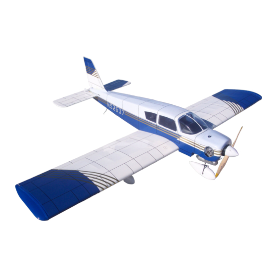
PIPER
INSTRUCTION MANUAL
• Extensive Hardware Included to Save Money
• Pre-Covered Realistic Trim Scheme
• Semi-Symmetrical Airfoil
90
%
PRE-BUILT
ALMOST READY-TO-FLY
TM
TM
WE GET PEOPLE FLYING
Specifications
Wingspan:
. . . . . . . . . . . . . . . . . . . . . . . . . . . . . . . . . . . .
Length:
. . . . . . . . . . . . . . . . . . . . . . . . . . . . . . . . . . .
Wing Area:
. . . . . . . . . . . . . . . . . . . . . . . . . . .
Weight (Approx.):
. . . . . . . . . . . . . . . . .
Recommended Engines:
.40–.46 2-cycle
. . .
.45–.56 4-cycle
62"
45-1/2"
720 sq. in.
6–6.25 lbs.
Advertisement
Table of Contents

Related Manuals for Hangar 9 Piper Cherokee


Summary of Contents for Hangar 9 Piper Cherokee
-
Page 1: Instruction Manual
PIPER WE GET PEOPLE FLYING INSTRUCTION MANUAL • Extensive Hardware Included to Save Money • Pre-Covered Realistic Trim Scheme • Semi-Symmetrical Airfoil Specifications Wingspan: 62" ........Length: 45-1/2"... -
Page 2: Table Of Contents
Table of Contents Introduction Warning Additional Equipment Required Tools and Supplies Required Contents of Kit Field Equipment Required Optional Field Equipment Section 1: Assembling the Wings Section 2: Joining the Wing Halves Section 3: Installing the Aileron Servo Tray Section 4: Mounting the Wing Section 5: Assembling the Fuselage Section 6: Installing the Tail Section 7: Hinging the Vertical &... -
Page 3: Introduction
Introduction Congratulations on your purchase of the Hangar 9 Piper Cherokee. This is the ideal second airplane for modelers who are capable of flying a trainer-type aircraft. In a few short evenings, this 90% pre-built beauty will be ready for its debut at the flying field. -
Page 4: Tools And Supplies Required
Tools and Supplies Required Adhesives Thin CA (cyanoacrylate) glue Thick CA (cyanoacrylate) glue 6-minute epoxy 12-minute epoxy 30-minute epoxy Blue Locktite 242 Canopy glue Tools Drill Drill bits: 1/16′′, 5/32′′ Small Phillips screwdriver Medium Phillips screwdriver Z-bend pliers Pliers Small round file Razor saw Moto-Tool with sanding drum Hobby knife with #11 blade... -
Page 5: Contents Of Kit
Contents of Kit Covered Parts A. Fuselage D. Vertical stabilizer with rudder B. Left wing half with aileron E. Horizontal stabilizer with elevator C. Right wing half with aileron Other 1. Pushrod & accessories 9. Foam wheels (3) 2. 1/8′′ plywood die-cut parts 10. -
Page 6: Field Equipment Required
Field Equipment Required Propeller Glow Plug Wrench Airplane Fuel Glow Plug Manual Fuel Pump Glow Driver... -
Page 7: Optional Field Equipment
Optional Field Equipment Field Box Cleaner & Towels 4-Way Wrench Misc. Tools After-Run Fuel Extra Glow Plugs Starter Power Panel #64 Rubber Bands 12V Sealed Battery... -
Page 8: Section 1: Assembling The Wings
Section 1: Assembling the Wings Parts Needed Tools and Adhesives Needed • Right wing panel with aileron and hinges • 30-minute epoxy • Left wing panel with aileron and hinges • Paper towels • Rubbing alcohol • Mixing stick/epoxy brush •... - Page 9 Section 1: Assembling the Wings CONTINUED Step 6. Mix a small amount of 30-minute epoxy to install the Step 7. Replace the aileron on the right wing half. Make sure aileron onto the wing half. Apply epoxy to the top and bottom of the hinges are properly aligned and that the aileron torque rod the remaining half of each hinge, as well as the aileron torque presses into its respective hole in the aileron.
-
Page 10: Section 2: Joining The Wing Halves
Section 2: Joining the Wing Halves Parts Needed Tools and Adhesives Needed • Right wing panel from Section One • 6-minute epoxy • Left wing panel from Section One • 30-minute epoxy • Three plywood wing joiners • Clips (e.g., clothespins, binder clips) •... - Page 11 Section 2: Joining the Wing Halves CONTINUED Step 5. Allow the epoxy to cure completely prior to removing Step 9. Place the wing halves on the flat surface so the white the clamps. side (bottoms) are facing downward. Using a felt tipped pen, place a mark at the leading edge and trailing edge of the servo Step 6.
- Page 12 Section 2: Joining the Wing Halves CONTINUED Step 12. Coat one half of the dihedral brace with epoxy up to Step 13. Apply a generous amount of epoxy into the wing the center line drawn in Step 6. Install the epoxy-coated side of cavity of the other wing half.
- Page 13 Section 2: Joining the Wing Halves CONTINUED Step 15. Carefully slide the two wing halves together, ensuring Step 16. Apply masking tape to the wing joint to hold the wing they are accurately aligned. Firmly press the two halves together, together securely while the epoxy cures.
-
Page 14: Section 3: Installing The Aileron Servo Tray
Section 3: Installing the Aileron Servo Tray Parts Needed Tools and Adhesives Needed • Plywood aileron tray • Masking tape • Plywood aileron tray supports • Hobby knife • Aileron servo • Felt tipped pen • Wing center tape • 6-minute epoxy •... - Page 15 Section 3: Installing the Aileron Servo Tray CONTINUED Step 6. Using a felt tipped pen, trace around the inside edge of Step 9. Using the sharp hobby knife, carefully cut through the the aileron servo tray and then remove it from the wing. balsa wood and the covering along the lines that were drawn in Step 6 of this section.
- Page 16 Section 3: Installing the Aileron Servo Tray CONTINUED Step 11. Mix a small amount of 6-minute epoxy and apply it to one of the aileron servo supports between the two tabs. Position the aileron servo tray in place as shown and lightly spread epoxy along the joint between the aileron servo tray and the aileron servo support.
- Page 17 Section 3: Installing the Aileron Servo Tray CONTINUED Step 14. Locate the wing center tape and remove the adhesive backing. Starting at the front of the aileron servo tray, wrap the tape completely around the wing joint seam to the rear of the servo tray.
-
Page 18: Section 4: Mounting The Wing
Section 4: Mounting the Wing Parts Needed Tools and Adhesives Needed • Complete wing assembly • Drill 1/4′′ drill bit • Wing dowel rods (2) • Medium Phillips screwdriver • Fuselage Wing hold-down screws/washers (2) • Small round file Note: Blind nuts are already mounted •... - Page 19 Section 4: Mounting the Wing CONTINUED Step 5. Once the wing dowels are dry, trial fit the wing to the Step 7. Bolt the wing to the fuselage. Turn the aircraft upside fuselage by inserting the leading edge of the wing into the dowel down and, using a ruler, hold one end of the ruler on the holes in the fuselage and placing the wing trailing edge in its fuselage reference point you made, and the other end of the ruler...
-
Page 20: Section 5: Assembling The Fuselage
Section 5: Assembling the Fuselage Parts Needed Tools and Adhesives Needed • Fuselage • Canopy glue (e.g., R/C 56 or Pacer 256) • Plywood servo tray • 12-minute epoxy • Front windshield • Masking tape • Clear plastic sheet for side windows •... - Page 21 Section 5: Assembling the Fuselage CONTINUED Step 3. Trim out the opening of the front windshield. It helps to Step 6. Remove any masking tape from the windows before use a felt tipped marking pen to outline the opening before installing the seats.
- Page 22 Section 5: Assembling the Fuselage CONTINUED Step 8. Trim the front windshield and trial fit it to the fuselage. Step 9. Before installing the servo tray, place the servos into Once you are satisfied with the fit, use canopy glue to install the each opening and mark the screw hole locations.
-
Page 23: Section 6: Installing The Tail
Section 6: Installing the Tail Parts Needed Tools and Adhesives Needed • Fuselage • Hobby knife • Horizontal stabilizer with elevator • Ruler • Vertical stabilizer with rudder • Felt tipped pen • Masking tape • Pencil • 30-minute epoxy •... - Page 24 Section 6: Installing the Tail CONTINUED Step 4. Locate the horizontal stabilizer. Using a ruler and a felt Step 6. Check the alignment of the horizontal stabilizer by tipped pen, mark the exact center on the top of the stabilizer. measuring from a fixed point along the center line of the fuselage to the leading edge on each side of the horizontal stabilizer.
- Page 25 Section 6: Installing the Tail CONTINUED Step 8. Remove the horizontal stabilizer from the fuselage. Step 10. Insert the horizontal stabilizer into the fuselage and Using a straight edge and a sharp hobby knife, carefully cut position it in the approximate location. Adjust the alignment as away the covering approximately 1/8′′...
- Page 26 Section 6: Installing the Tail CONTINUED Step 14. Mix approximately 1/4 ounce of 30-minute epoxy to Step 16. Wipe off any excess epoxy with a paper towel and install the vertical stabilizer. Using an epoxy brush or mixing rubbing alcohol, being careful not to disturb the alignment of the stick, spread the epoxy on the vertical stabilizer where it contacts vertical stabilizer.
-
Page 27: Section 7: Hinging The Vertical & Horizontal Stabilizers
Section 7: Hinging the Vertical & Horizontal Stabilizers Parts Needed Tools and Adhesives Needed • Fuselage • 30-minute epoxy • Horizontal stabilizer • Mixing stick • Vertical stabilizer • Paper towels • Rubbing alcohol Step 1. Carefully remove the rudder from the vertical stabilizer Step 5. -
Page 28: Section 8: Installing The Control Horns
Section 8: Installing the Control Horns Parts Needed Tools and Adhesives Needed • Control horns (2) • Drill • Control horn backplate (2) • 1/16′′ drill bit • Control horn screw (4) • Felt tipped pen or pencil • Fuselage •... - Page 29 Section 8: Installing the Control Horns CONTINUED Step 5. To mark the rudder control horn location, measure up Step 7. Drill these holes with a 1/16′′ drill bit and install the 1/2′′ from the fuselage on the left side of the rudder. Mark this rudder control horn using the two screws and backplate location using a felt tipped pen or pencil.
-
Page 30: Section 9: Assembling And Installing The Fuel Tank
Section 9: Assembling & Installing the Fuel Tank Parts Needed Tools and Adhesives Needed • Fuel tank • Medium Phillips screwdriver • Fuel tubing (not supplied) • Hobby knife • Fuel clunk • Aluminum tube, short (pickup) • Aluminum tube, short (optional fill tube) •... - Page 31 Section 9: Assembling & Installing the Fuel Tank CONTINUED Step 4. Slide this tube into the remaining hole in the black Step 6. Locate the silicone fuel tubing and the metal clunk. rubber stopper. Insert the fuel clunk into one end of the fuel tubing. This assembly will be used for the fuel pickup inside the fuel tank.
- Page 32 Section 9: Assembling & Installing the Fuel Tank CONTINUED Step 8. Carefully insert the assembly into the fuel tank and, Step 9. Place the foam fuel tank collar around the neck of the using the self-tapping screw, screw the stopper together firmly. fuel tank and press the fuel tank firmly against the firewall until It helps if the screw has been inserted in the assembly and the stopper inserts into the hole in the firewall.
-
Page 33: Section 10: Installing The Landing Gear
Section 10: Installing the Landing Gear Parts Needed Tools and Adhesives Needed • Main landing gear (2) • Epoxy brush • Landing gear straps — nylon (4) • Pencil • 2.6mm self-tapping screws (8) • 6-minute epoxy • Hobby knife •... - Page 34 Section 10: Installing the Landing Gear CONTINUED Step 5. Remove the landing gear mounting straps and the Step 6. Reposition the landing gear and straps as described landing gear from the wing. Using a 1/16′′ drill bit, drill the four previously.
-
Page 35: Section 11; Installing The Nose Gear
Section 11: Installing the Nose Gear Parts Needed Tools and Adhesives Needed • Nose gear • Medium Phillips screwdriver • Nose gear control horn with 3mm screw • Blue Locktite 242 • Wheel collar with 3mm screw (2) • Plastic spacer Step 1. -
Page 36: Section 12: Assembling And Mounting The Wheel Pants
Section 12: Assembling & Mounting the Wheel Pants Parts Needed Tools and Adhesives Needed • Wheel pants (3) • Drill • 2′′ foam wheels (3) • 5/32′′ drill bit • Wheel collars with screws (3) • Medium Phillips screwdriver • Wheel pant decal sheet •... - Page 37 Section 12: Assembling & Mounting the Wheel Pants CONTINUED Step 4. Slide the wheel pant assembly onto the left landing gear Step 5. Repeat this procedure for the right side of the landing strut until the strut is seated firmly against the slot in the wheel gear and for the nose gear.
-
Page 38: Section 13: Installing The Engine
Section 13: Installing the Engine Parts Needed Tools and Adhesives Needed • Engine • Medium Phillips screwdriver • Engine mounting bracket (2) • Blue Locktite 242 • Engine mounting screws and nuts (4 each) • Fuselage Step 1. Remove the two engine mounting brackets, four Step 3. -
Page 39: Section 14: Installing The Cowling
Section 14: Installing the Cowling Parts Needed Tools and Adhesives Needed • Cowling (blue half/white half) • Instant thin CA glue • Sheet metal screws (8) • CA remover/debonder • Fuselage • Scissors • Trim film • Masking tape • Drill •... - Page 40 Section 14: Installing the Cowling CONTINUED Step 4. Glue the two cowl halves together using thin CA. Step 6. Final trim of the cowl will depend on the type of engine Carefully hold the cowling halves together as you glue them. Be and the location of the spring of the nose wheel in relation to the careful the CA does not run.
-
Page 41: Section 15: Installing The Radio
Section 15: Installing the Radio Parts Needed Tools and Adhesives Needed • 4-channel radio system with four servos and hardware • Drill (not included) • 1/16′′ drill bit • Fuselage • Small Phillips screwdriver • Radio packing foam (not included) •... -
Page 42: Installing The Receiver
Section 15: Installing the Radio CONTINUED Step 5. Remove the servos and, using a 1/16′′ drill bit, drill the Installing the Receiver 12 mounting holes as marked. Re-install the servos, again and Battery Pack noting the position of the output horns. Screw the servos in place using the 12 servo screws, which are included with the Step 6. - Page 43 Section 15: Installing the Radio CONTINUED Installing the Switch Step 10. Remove the switch plate from the fuselage. Using a 1/16′′ drill bit, drill the two mounting holes as marked. Step 8. The switch should be mounted on the left side of the fuselage away from the potentially harmful exhaust gases.
-
Page 44: Section 16: Installing The Linkages
Section 16: Installing the Linkages Parts Needed Tools and Adhesives Needed • Aileron horns (2) • Z-bend pliers • Long (17-3/4′′) threaded rods (2) • Ruler • Wing • Thick CA glue • Heat shrink tubing • Hobby knife • Clevises (5) •... -
Page 45: Rudder Pushrod
Section 16: Installing the Linkages CONTINUED Step 6. Adjust the aileron torque rod length by screwing in or Step 11. Insert the 90-degree bend into the hole of the balsa out until the aileron is exactly in the neutral position when the dowel and saturate the balsa with thick CA glue where the rod servo is centered and the clevis is in the aileron horn. - Page 46 Section 16: Installing the Linkages CONTINUED Step 15. Slide a piece of heat shrink tubing over the end of the Step 18. Screw on a clevis 12 complete turns. Fasten the clevis balsa dowel and shrink it in place using a heat gun. in the third hole from the inside of the rudder control horn.
-
Page 47: Throttle Linkage
Section 16: Installing the Linkages CONTINUED Step 21. Insert the Z-bend into the servo arm. It may be Step 27. Using Z-bend pliers, make a Z-bend at the marked necessary to enlarge the servo arm hole slightly to accept the location on the rod. - Page 48 Section 16: Installing the Linkages CONTINUED Step 33. Using Z-bend pliers, make a Z-bend at the marked Step 39. Be sure that the rudder servo is centered. Using a felt spot on the rod. Remove the excess rod. tipped pen, place a mark on the unthreaded end of the steering pushrod where it passes the nose wheel steering arm.
-
Page 49: Section 17: Plumbing The Engine
Section 17: Plumbing the Engine Parts Needed Tools and Adhesives Needed • Fuselage • Scissors or sharp hobby knife to cut tubing • Engine • Fuel tubing Step 1. Install the muffler per the instructions included with the Step 2. Connect the vent tube from the fuel tank to the pressure engine. -
Page 50: Section 18: Control Throw Recommendations
Section 18: Control Throw Recommendations The following control throws offer the most positive response Aileron: 9/32′′ up, 9/32′′ down and are a good place to begin. After you’ve become more Elevator: 3/8′′ up, 3/8′′ down familiar with the flight characteristics of the Cherokee, adjust the Rudder: 1′′... -
Page 51: Pre-Flight Check
Pre-Flight Check Step 1. Check that all control functions move in the correct Note: Mode II transmitter shown in diagram. direction. If not, use the respective reversing switch to correct the direction. Step 2. Check that each clevis is securely snapped into position. -
Page 52: Pre-Flight At The Flying Field
Pre-Flight at the Flying Field Range Test Your Radio Adjusting the Engine Step 1. Before each flying session, be sure to range check your Step 1. Completely read the instructions included with your radio. This is accomplished by turning on your transmitter with engine and follow the recommended break-in procedure. -
Page 53: Ama Safety Code
AMA Safety Code 1994 Official AMA National Model Aircraft Safety Code I will not operate models with pyrotechnics (any device that explodes, burns, or propels a projectile of any kind) including, but not limited Effective January 1, 1994 to, rockets, explosive bombs dropped from models, smoke bombs, all Model flying must be in accordance with this Code in explosive gases (such as hydrogen-filled balloons), ground mounted order for AMA liability protection to apply... - Page 54 © Copyright 1998, Horizon Hobby Distributors, Inc.
Need help?
Do you have a question about the Piper Cherokee and is the answer not in the manual?
Questions and answers