
Related Manuals for Hangar 9 HAN2990


Summary of Contents for Hangar 9 HAN2990
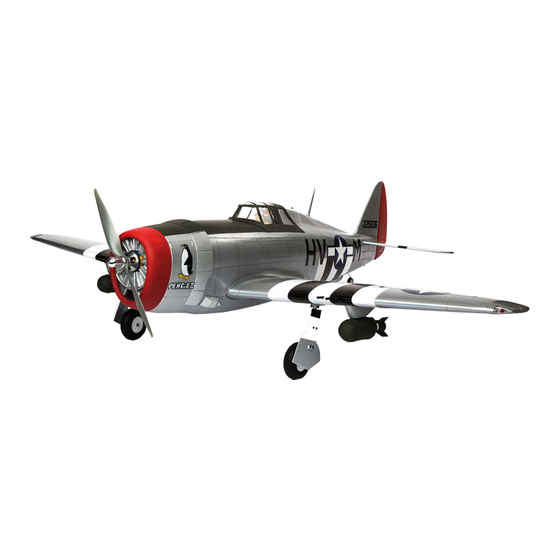
- Page 1 P-47D Thunderbolt 20cc Instruction Manual Bedienungsanleitung Manuel d’utilisation Manuale di Istruzioni...
- Page 2 SPECIFICATIONS • SPEZIFIKATIONEN • SPÉCIFICATIONS • SPECIFICHE 67 in (1700 mm) 825 sq in (53.2 dm2) Total/Totale 58 in (1473 mm) 11–13 lbs (5–6 kg) 2-Stroke Gas: 20cc, 4-Stroke gas/petrol: 20cc 2-Takt Benziner: 20cc, 4-Takt Benzin: 20 cc 2 temps Essence: 20cc, 4 temps essence: 20cc 2-Tempi Gas: 20cc, 4 tempi benzina: 20 cc Electric Power: Power 60, 470Kv Brushless Elektro Antrieb Power: Power 60, 470Kv Brushless...
- Page 3 Part # English Deutsch Français Italiano REPLACEMENT PARTS • ERSATZTEILE • PIÈCES DE RECHANGE • PEZZI DI RICAMBIO A HAN299001 Fuselage with Hatch Rumpf mit Haube Fuselage avec capot Fusoliera con portello B HAN299002 Left Wing with Aileron and Flap Tragfl...
- Page 4 Motore a benzina 20GX 20cc (1.20 cu. in.) HAN116 Fuel Filler with “T” and Overfl ow Fitting Hangar 9 Tanknippel mit T Stück u. Überlauf Fitting Point de remplissage de carburant avec coupleur en T Bocchettone di riempimento carburante con...
- Page 5 Part # English Deutsch Français Italiano REQUIRED TOOLS • BENÖTIGTES WERKZEUG • OUTILS REQUIS • ATTREZZI NECESSARI Box wrench: 1/2-inch Ringschlüssel: 1/2-inch Clé hexagonale: 1/2-inch Chiave esagonale: 1/2-inch Drill Bohrer Mini-perceuse Trapano Drill bit: 1/16-inch, 5/64-inch, 1/8-inch Punte per trapano: 1,5mm, 2mm, 3mm, 4mm, Bohrer: 1,5mm, 2mm, 3mm, 4mm, 4,5mm Forêt : 1,5mm, 2mm, 3mm, 4mm, 4,5mm 5/32-inch, 3/16-inch...
-
Page 6: Before Starting Assembly
NOTICE Batteries Always follow the manufacturer’s instructions when using and disposing of any batteries. Mishandling of Li-Po All instructions, warranties and other collateral documents are subject to change at the sole discretion of Horizon batteries can result in fi re causing serious injury and damage. Hobby, LLC. -
Page 7: Vor Dem Zusammenbau
HINWEIS Propeller Halten Sie lose Gegenstände die sich im Propeller verfangen können weg vom Propeller. Dieses gilt auch für Kleidung Alle Anweisungen, Garantien und anderen zugehörigen Dokumente können im eigenen Ermessen von Horizon Hobby, oder andere Objekte wie zum Beispiel Stifte oder Schraubendreher. LLC. -
Page 8: Avant De Commencer L'assemblage
REMARQUE L’hélice Gardez éloignés tous les éléments qui pourraient être attrapés par l’hélice. Cela inclut les vêtements larges ou les La totalité des instructions, garanties et autres documents est sujette à modifi cation à la seule discrétion d’Horizon objets comme des outils par exemple. Gardez toujours vos mains à distance pour éviter tout cas de blessures. Hobby, LLC. -
Page 9: Precauzioni Per La Costruzione
AVVISO Elica Tenere gli oggetti liberi (vestiti, penne, cacciaviti, ecc.) lontano dall’elica, prima che vi restino impigliati. Bisogna fare Tutte le istruzioni, le garanzie e gli altri documenti pertinenti sono soggetti a cambiamenti a totale discrezione di attenzione anche con le mani perché c’è il rischio di ferirsi anche gravemente. Horizon Hobby, LLC. - Page 10 TRANSPORTATION AND STORAGE TRANSPORT UND LAGERUNG TRANSPORT ET STOCKAGE TRASPORTO E DEPOSITO Use the 3-view drawing at the back of this manual to Mit der Zeichnung aus drei Ansichten am Ende des Utilisez le schéma à 3 vues à l’arrière de ce manuel Fare riferimento al trittico riportato sul retro di questo determine the amount of space required to transport and Handbuchs lässt sich ermitteln, wie viel Platz zum...
-
Page 11: Flap Installation
FLAP INSTALLATION Run your fi nger down the lower surface leading edge of the fl ap to locate the areas for the fl ap hinges. Use Use a piece of low-tack tape to hold the aileron in a hobby knife and #11 blade to remove the covering, position. -
Page 12: Aileron Installation
10. Apply epoxy to each hinge where it will be inserted into AILERON INSTALLATION the fl ap. Insert the hinges as shown in Step 6. 15. Remove the tape and aileron from the wing panel. 11. Apply epoxy to each hinge where it will be inserted into 16. -
Page 13: Aileron Servo Installation
20. Allow the CA to cure for 10 to 15 minutes. Gently pull on 25. Apply epoxy to the area of the control horns that fi ts into the fi xed surface and control surface to make sure the the slots. Use enough epoxy so the control horns will be hinges are glued securely. - Page 14 30. Thread an M2 x 10 sheet metal screw into each hole 35. Secure a 12-inch (300mm) servo extension to the servo using a #1 Phillips screwdriver. Remove the screws using a commercially available fastener (SPMA3054). before proceeding. 31. Apply a small amount of thin CA to harden the threads 36.
-
Page 15: Flap Servo Installation
40. Attach the clevis to the inside hole on the aileron control 45. Slide the keeper tightly against the servo arm. Use pliers horn. to snap the keeper on the pushrod wire. 41. Center the aileron servo using the radio system. With 46. - Page 16 50. Secure an 3-inch (75mm) servo extension to the servo 54. Use the radio system to move the servo to the UP fl ap using a commercially available fastener (SPMA3054). position. Use a felt-tipped pen to mark the pushrod Secure the servo in the wing using a #1 Phillips where it crosses the outer hole in the servo arm.
-
Page 17: Fixed Gear Installation
59. Secure the servo arm to the servo. Secure the clevis to 64. Use a hobby knife and #11 blade to remove the covering the control horn following the same procedures as the from the mounting rails in the wing. Trim the covering aileron linkage. -
Page 18: Retract Installation
69. Slide the M5 washer on the M5 x 45 socket head cap RETRACT INSTALLATION screw. Slide the screw into the wheel. Make sure the wheel rotates freely on the screw. If not, use a hobby Skip this section of the manual if the fixed knife with a #11 blade or 5mm drill bit to remove any gear has been installed on your model. - Page 19 79. Fit the retract frame to the wing. Guide the servo 84. Slide the axle into the retract strut. Tighten the setscrew extension through the wing, exiting the same location as to secure the axle to the strut. Make sure the wheel can the fl...
-
Page 20: Stabilizer And Rudder Installation
88. Check that there is a slight amount of toe-in (roughly 92. Slide the wing panel into position. Guide the fl ap and 1-degree). Adjustments can be made by loosening the aileron leads into the fuselage. setscrews on the retract frame. After adjusting the toe in, check the alignment of the wheel as it retracts into the wheel well to verify that it is not binding in the up position. - Page 21 97. Stand back 8-10 feet (2-3 meters) and check that 102. Use an epoxy brush to apply epoxy to the stabilizer 102. the stabilizer is aligned with the wing. Lightly sand mounting surface for the stabilizer. the stabilizer saddle on the fuselage to correct any misalignment.
-
Page 22: Elevator And Rudder Servo Installation
107. Locate the red rudder control horn. Use medium grit- 112. Secure the receiver in the fuselage using hook and 107. 112. sandpaper to remove the paint from the bottom of the loop tape and hook and loop straps. Locate the remote control horn where it fi... -
Page 23: Tail Wheel Assembly Installation
117. Complete the installation be installing the rudder 122. Remove the nut from the pushrod and install it into the 117. 122. pushrod. Make sure to slide all clevis retainers into tube from inside the fuselage. Thread the nut on the position, and use threadlock on all metal-to-metal pushrod and prepare the clevis with a clevis retainer. - Page 24 126. Use a drill and 7/32-inch (5.5mm) drill bit to enlarge the 131. Align the X-mount on the centerlines on the fi rewall. Use 126. 131. holes to mount the engine. a felt-tipped pen to mark the locations for the mounting positions.
- Page 25 136. Use a press to carefully reposition the motor shaft so it 141. Use a felt-tipped pen to mark the location of the sliding 136. 141. is fl ush with the face of the bell housing. Apply a drop fi rewall on the outside of the motor box. of threadlock on each of the setscrews.
-
Page 26: Gas Engine Installation
146. Remove the battery tray from the fuselage using a #1 151. Use hook and loop tape to mount the speed control to the 146. 151. Phillips screwdriver. Secure the receiver battery in the fuselage. Connect the leads from the motor and speed area below the battery tray. - Page 27 154. Use a drill and 7/32-inch (5.5mm) drill bit to enlarge the 159. Remove the engine from the mounts. Use a drill and 154. 159. holes to mount the engine. 5/32-inch (4mm) drill bit to drill the holes for the engine mounting screws.
- Page 28 164. Remove the fuel tank fl oor from the fuselage by 169. Slide the throttle pushrod into the pushrod tube. Connect 164. 169. removing the four screws with a #1 Phillips screwdriver. the Z-bend in the throttle pushrod to the carburetor arm. Secure the ignition module in the fuselage.
-
Page 29: Fuel Tank Installation
174. Check that the carburetor opens fully. Adjust the settings 179. Attach the clunk included with the kit to the stopper. 174. 179. in the radio if necessary to fully open the carburetor Secure the tubing to the stopper and clunk. without binding the servo. -
Page 30: Cowling Installation
184. Use medium CA to glue the fuel tank braces in the 189. Slide the cowling into position. Attach the propeller to the 184. 189. fuselage. Slide the fuel tank back against the rear brace motor shaft using the hardware included with the engine. once the CA fully cures. -
Page 31: Scale Accessory Installation
194. Apply a coat of 15-minute epoxy to the mounts where 199. Lightly sand the inside edge of the canopy using medium 194. 199. the fi t to the cowling. grit sandpaper. Remove any oils or debris with a paper towel and isopropyl alcohol. - Page 32 204. Remove the covering on the bottom of the wing for the 209. Check that the guns are aligned as shown in the photo. If 204. 209. bomb mounts. there are any alignment issues, use a 15/64-inch (6mm) drill bit to carefully alter the holes. Once aligned, use 15-minute epoxy to glue the guns into position.
-
Page 33: Center Of Gravity
CENTER OF GRAVITY CONTROL THROWS An important part of preparing the aircraft for fl ight is properly balancing the model. Turn on the transmitter and receiver of your model. Check the movement of the rudder using the transmitter. When the stick is moved to the right, the rudder should also move right. Reverse the direction of the servo at the Attach the wing panels to the fuselage. -
Page 34: Preflight Checklist
PREFLIGHT CHECKLIST DAILY FLIGHT CHECKS LIMITED WARRANTY Limitation of Liability HORIZON SHALL NOT BE LIABLE FOR SPECIAL, INDIRECT, • Charge the transmitter, receiver and motor battery for • Check the battery voltage of the transmitter battery. What this Warranty Covers INCIDENTAL OR CONSEQUENTIAL DAMAGES, LOSS OF your airplane. -
Page 35: Warranty And Service Contact Information
Inspection or Services Warranty Requirements WARRANTY AND SERVICE CONTACT INFORMATION If this Product needs to be inspected or serviced and is For Warranty consideration, you must include your compliant in the country you live and use the Product original sales receipt verifying the proof-of-purchase Country in, please use the Horizon Online Service Request date. - Page 36 INSTALLATION DER KLAPPE Mit dem Finger entlang der unteren Vorderkante der Klappe fahren, um die korrekten Stellen für die Klappen- Mit einem kleinen Stück des Klebebands mit geringer Aufhängungen zu fi nden. Mit einem Hobbymesser und Klebekraft das Querruder in Position halten. Dies hält das einer Nr.
- Page 37 10. Epoxid an der Stelle auf jede Aufhängung auftragen, die MONTAGE DES QUERRUDERS in die Klappe eingeführt wird. Die Aufhängungen wie in 15. Klebeband und Querruder von der Tragfl äche entfernen. Schritt 6 einsetzen. 11. Epoxid an der Stelle auf jede Aufhängung auftragen, die 16.
- Page 38 20. Den CA-Klebstoff ca. 10 bis 15 Minuten aushärten 25. Epoxid auf den Bereich der Steuerhörner auftragen, der lassen. Vorsichtig an der festen Fläche und Steuerfl äche in die Schlitze passt. Ausreichend Epoxid verwenden, ziehen, um sicherzustellen, dass die Aufhängungen sodass sich die Steuerhörner vollständig mit den festen sicher verklebt sind.
- Page 39 30. Eine M2 x 10-Blechschraube mit einem Nr.1- 35. Eine 300 mm (12 Zoll) Servoverlängerung am Servo Kreuzschlitzschraubendreher in jedes Loch schrauben. mit einem käufl ich erhältlichen Befestiger (SPMA3054) Die Schrauben vor dem Fortfahren entfernen. befestigen. 31. Eine kleine Menge dünnen CA-Klebstoff zum Härten der 36.
- Page 40 40. Den Gabelkopf im inneren Loch des Steuerhorn des 45. Den Anker an den Servoarm schieben, bis er eng anliegt. Querruders anbringen. Mit einer Zange den Anker auf dem Gestängedraht einschnappen. 41. Den Servo des Querruders mit dem Funksystem 46. Mit Seitenschneidern den Gestängedraht 1,5 mm zentrieren.
- Page 41 49. Den Gabelkopf am Klappen-Steuerhorn befestigen. 53. Die Klappe in die Aufwärtsposition bringen. Wir empfehlen die Verwendung von Klebeband mit geringer Klebekraft, um die Klappe während der nächsten Schritte in Position zu halten. 50. Eine 75 mm (3 Zoll) Servoverlängerung am 54. Mit dem Funksystem den Servo in die Klappen- Servo mit einem käufl...
- Page 42 58. Den Servo mit dem Funksystem in die obere 63. Die Fahrwerkstrebe an der Halterung befestigen. Klappenposition bringen. Den Ruderausschlag im Gewindekleber für die Feststellschraube verwenden, Funksystem anpassen, um die Klappe auf die Hinterkante bevor sie auf dem fl achen Bereich der Strebe angezogen des Flügels auszurichten.
- Page 43 68. Die Halterungen der Fahrwerkklappe auf die Fahrwerk- 72. Die Fahrwerkklappen-Halterungen so platzieren, Streben schieben. Die Position der Halterungen wird bei dass eine 3 mm (1/8 Zoll) große Lücke zwischen der Installation der Fahrwerkklappe justiert. Fahrwerkklappe und Flügel besteht. Vier M3 x 6 Rundkopfschrauben verwenden, um die Fahrwerkklappen an den Fahrwerkklappen-Halterungen zu befestigen.
- Page 44 75. Die Fahrwerkklappen-Halterung nahe der Öffnung in 80. Das einziehbare Fahrwerk mit der beigelegten Hardware der Fahrwerkklappe platzieren. Mit einem Filzstift die am Flügel befestigen. Position der Befestigungsschrauben des Motors auf der Fahrwerkklappe markieren. Bei Metall-Metall-Befestigern stets Gewindekleber verwenden. Es kann erforderlich sein, die dem einziehbaren Fahrwerk beigeliegten Abstandshalter zu verwenden, um sicherzustellen, dass keine Torsionsspannung am Fahrwerk anliegt, wenn es festgezogen wird.
- Page 45 85. Die Funktion des einziehbaren Fahrwerks mit dem INSTALLATION VON STABILISATOR UND Funksystem prüfen. Das Rad muss in der Öffnung SEITENRUDER zentriert sein. Falls nicht, die Montageschrauben lockern und bei Bedarf ausrichten. 89. Den Verriegelungsschalter der Abdeckung zur Vorderseite des Rumpfs bewegen. Dem einziehbaren Fahrwerk liegen Abstandshalter bei.
- Page 46 94. Mit einer scharfen Säge den Heckpfosten am Ende des 99. Mit einem Filzstift den Umriss des Rumpfes auf die Rumpfs entfernen. Mit Sandpapier mit mittlerer Körnung Unterseite des Stabilisators übertragen. den Bereich abfl achen, sodass der Stabilisator in die Öffnung passt.
- Page 47 Der Flügel kann nun vom Rumpf abgenommen werden. 109. Das Seitenruder an das Seitenleitwerk anpassen. 104. 109. Die Spitze des Seitenruders mit der Oberseite des 104. Die zwei silbernen Steuerhörner des Höhenruders Seitenleitwerks ausrichten. Die Aufhängungen verkleben; lokalisieren. Mit Sandpapier mittlerer Körnung die Farbe 15/16 inch hierzu das bereits beschriebene Verfahren für die vom unteren Teil des Steuerhorns entfernen, der in das...
- Page 48 114. Den Höhenruder-Servo mit dem Funksystem zentrieren. MONTAGE DER SPORNRADBAUGRUPPE 114. 119. Das Gestänge nach demselben Verfahren wie die 119. Die Metallbuchse auf das Spornradkabel und daraufhin Querruder- und Klappengestänge montieren. Das das Spornrad schieben. Gewindekleber auf die Gestänge wird mit der Öffnung im Höhenruder-Servoarm M3-Feststellschraube auftragen.
-
Page 49: Montage Des Elektromotors
124. Die Spornradabdeckung wieder anbringen. 128. Die Mittelinien der Schablone auf die Mittellinien des 124. 128. Motorkastens ausrichten. Mit Klebeband die Schablone am Motorkasten sichern. Sicherstellen, dass alle An der vorderen Innenkante der Spornradabdeckung Bohrstellen klar erkennbar sind, wenn die Schablone am kann sich eine hölzerne Querstange befinden, die Motorkasten befestigt wird. - Page 50 133. Die dem Motor beiliegenden Blindmuttern auf der 138. Die X-Halterung am Motor anbringen. Einen Tropfen 133. 138. Rückseite der Motorkasten-Platte einsetzen. Gewindekleber auf jeder der dem Motor beiliegenden Schrauben platzieren, daraufhin mit einem Nr. 2-Kreuzschlitzschraubendreher die Schrauben festziehen, mit denen die Halterung am Motor montiert wird.
- Page 51 143. Ist das Epoxid vollständig ausgehärtet, den dreieckigen 148. Klettband an der Akkuhalterung befestigen. Zwei 143. 148. Schaft in der Innenseite des Motorkastens montieren. Klettbänder durch die Öffnungen der Akkuhalterung Den dreieckigen Schaft so schneiden, dass er die führen. Blindmuttern nicht abdeckt und genau in die Ecken des Motorkastens passt.
- Page 52 MONTAGE DES GASMOTORS 157. Den Motor in die Halterung einsetzen und mit einer 157. Klemme in Position halten. Den Motor so positionieren, dass sich die Vorderseite der Unterlegscheibe des Motors Wurde ein elektrischer Motor installiert, mit dem 159 mm (6 Zoll) vor dem Brandschott befi ndet. Abschnitt „Montage der Motorhaube“...
- Page 53 162. Mit einem 4-mm-Bohrer (5/32 Zoll) das Loch für das 166. Den Schalter für den Empfänger und das Zündmodul 162. 166. Gasgestänge bohren. Das Loch in der Nähe der Halterung im Rumpf montieren. Die Schalter befi nden sich und des vorstehenden Abschnitts des Brandschotts nach der Installation auf gegenüberliegenden Seiten lokalisieren.
- Page 54 171. Bei im Servo befestigtem Servoarm den Sender 176. Prüfen, ob sich die Drossel schließt. Das Gestänge nach 171. 176. einschalten und Gas- und Trimhebel in die mittige Bedarf justieren. Position bringen. Den Servoarm am Servo parallel zur Mittellinie des Servos platzieren. Justierungen können zudem mit dem Funksystem vorgenommen werden, wenn ein Computer-Funksystem verwendet wird.
-
Page 55: Montage Der Motorhaube
181. Eine 127-mm-Kraftstoffl eitung (5 Zoll) an der Füllleitung Den Sternmotor trimmen, NUR GAS. 181. 186. des Kraftstoffbehälters sichern. Die Überlauf-Leitung 186. Die Motorattrappe wie dargestellt trimmen, sodass Luft kann an der Entlüftung sowie an der verbleibenden über den Motor fl ießen und den Vergaser reinigen kann. Leitung zur Pendel-Leitung angebracht werden, die Das Material in der Mitte der Motorattrappe für die am Ende am Vergaser angebracht wird. - Page 56 191. Die Position der Halterungen mit einem Filzstift an der 196. Die Kraftstoffl eitungen und den Schalldämpfer 191. 196. Innenseite der Motorhaube markieren. Sicherstellen, dass befestigen. Sicherstellen, dass alle Verbindungen am sich die Motorhaube beim Zeichnen der Markierungen Motor befestigt werden, sodass diese nicht vibrieren und nicht bewegt.
- Page 57 201. Die Abdeckung von der Oberseite des Rumpfs entfernen, 206. Die Bomben mit zwei M3 x 10 Schrauben und zwei M3 201. 206. um die Antenne anzubringen. Die Antenne in die Muttern an den Bombenhalterungen befestigen. Mit vorinstallierte Mutter im Rumpf setzen. einem Nr.
-
Page 58: Der Schwerpunkt
DER SCHWERPUNKT RUDERAUSSCHLAG Ein wichtiger Teil bei der Vorbereitung des Flugzeugs für den Flug ist das ordnungsgemäße Ausbalancieren des Den Sender und Empfänger des Modells einschalten. Die Bewegung des Seitenruders mit der Fernsteuerung Modells. prüfen. Wird der Steuerhebel nach rechts bewegt, sollte sich auch das Seitenruder nach rechts bewegen. Die Richtung auf dem Servo am Empfänger bei Bedarf umkehren. -
Page 59: Garantie Und Service Informationen
VORFLUGKONTROLLE TÄGLICHER FLUG CHECK GARANTIE UND SERVICE Horizon behält sich vor, alle eingesetzten Komponenten zu prüfen, die in den Garantiefall einbezogen werden INFORMATIONEN • Laden Sie den Sender- ,Empfänger- und Zündakku • Überprüfen Sie die Spannung des Senderakkus. können. Die Entscheidung zur Reparatur oder zum für Ihr Flugzeug. -
Page 60: Garantie Und Service Kontaktinformationen
Sicherheitshinweise Fragen, Hilfe und Reparaturen Bitte legen Sie dem Produkt einen Kaufbeleg bei, sowie ACHTUNG: Kostenpfl ichtige Reparaturen nehmen wir Dieses ist ein hochwertiges Hobby Produkt und kein Ihr lokaler Fachhändler und die Verkaufstelle können eine ausführliche Fehlerbeschreibung und eine Liste aller nur für Elektronik und Motoren vor. -
Page 61: Installation Des Volets
INSTALLATION DES VOLETS Parcourez le bord d’attaque de la surface inférieure du volet avec votre doigt pour trouver les emplacements des Utilisez un morceau de ruban à faible adhérence pour charnières du volet. Utilisez un couteau et une lame n° maintenir l’aileron en place. - Page 62 10. Appliquez de la colle époxy sur chaque charnière qui INSTALLATION DE L’AILERON s’insérera dans le volet. Insérez les charnières comme 15. Retirez le ruban et l’aileron du panneau de l’aile. indiqué dans l’étape 6. 11. Appliquez de la colle époxy sur chaque charnière qui 16.
-
Page 63: Installation Du Servo De L'aileron
20. Laissez la CA sécher pendant 10 à 15 minutes. Tirez 25. Appliquez de la colle époxy sur la partie des renvois délicatement sur la surface fi xe et la surface de de commande qui rentre dans les fentes. Utilisez commande pour vérifi... - Page 64 30. Vissez une vis à tôle M2 x 10 dans chaque trou à l’aide 35. Fixez une rallonge de servo de 300 mm (12 po) au servo d’un tournevis cruciforme n° 1. Retirez les vis avant de à l’aide d'une attache disponible dans le commerce continuer.
- Page 65 40. Fixez la manille sur le trou intérieur du renvoi de 45. Glissez la butée fermement contre le bras de servo. commande de l’aileron. Utilisez une pince pour enclencher la butée sur le fi l de barre de liaison. 41. Centrez le servo de l’aileron à l’aide du système radio. 46.
- Page 66 50. Fixez une rallonge de servo de 75 mm (3 po) au servo 54. Utilisez le système radio pour mettre le servo en position à l’aide d'une attache disponible dans le commerce volet relevé. Utilisez un stylo-feutre pour marquer la (SPMA3054).
- Page 67 59. Fixez le bras de servo sur le servo. Fixez la manille au 64. Utilisez un couteau et une lame n° 11 pour retirer renvoi de commande en suivant les mêmes procédures l’entoilage des rails de montage dans l’aile. Taillez que pour la tringlerie de l’aileron.
- Page 68 69. Glissez la rondelle M5 sur la vis d’assemblage à six pans INSTALLATION DU SYSTÈME DE RENTRÉE creuse M5 x 45. Glissez la vis dans la roue. Veillez à ce que la roue pivote librement sur la vis. Si ce n’est pas Passez ce chapitre du manuel si le train le cas, utilisez un couteau avec une lame n°...
- Page 69 79. Insérez le châssis de rentrée dans l’aile. Guidez la 83. Posez une entretoise en nylon sur l’axe. rallonge de servo à travers l’aile, en la faisant sortir au même endroit que les fi ls de servos de volet et d’aileron. Assurez-vous de marquer chaque fil de servo de façon à...
- Page 70 88. Vérifi ez la présence d'un léger pincement (environ 1 92. Remettez le panneau d’aile dans sa position. Guidez les degré). Des ajustements peuvent être effectués en fi ls de volet et d’aileron dans le fuselage. desserrant les vis de fi xation sur le châssis de rentrée. Après avoir ajusté...
- Page 71 97. Reculez de 2 ou 3 mètres (8-10 pieds) et vérifi ez que le 102. Utilisez une brosse spéciale pour appliquer la colle 102. stabilisateur est aligné avec l’aile. Poncez légèrement le époxy sur la surface de montage du stabilisateur pour le pontet du stabilisateur sur le fuselage pour corriger tout stabilisateur.
- Page 72 107. Localisez le renvoi de commande rouge de la gouverne 112. Fixez le récepteur dans le fuselage à l’aide de sangles 107. 112. de direction. Utilisez un papier abrasif de grain moyen et de bandes velcro. Repérez le récepteur à distance en pour retirer la peinture du bas du renvoi de commande à...
-
Page 73: Installation Du Moteur Électrique
117. Terminez l’installation en installant la barre de liaison de 122. Retirez l’écrou de la barre de liaison et installez-le dans 117. 122. la gouverne de direction. Assurez-vous de glisser toutes le tube par l’intérieur du fuselage. Filetez l’écrou sur la les bagues de retenue de manille en place, et utilisez du barre de liaison et préparez la manille avec une bague de frein-fi... - Page 74 126. Utilisez une perceuse et une mèche de 5,5 mm (7/32 po) 131. Alignez le support en X sur les lignes de centre sur 126. 131. pour agrandir les trous pour monter le moteur. le pare-feu. Utilisez un stylo-feutre pour marquer l’emplacement des positions de montage.
- Page 75 136. Utilisez une presse pour repositionner soigneusement 141. Utilisez un stylo-feutre pour marquer l’emplacement 136. 141. l’arbre du moteur de manière à ce qu’il soit affl eurant destiné au pare-feu coulissant à l’extérieur du boîtier du avec la façade du lanterneau. Appliquez une goutte de moteur.
-
Page 76: Installation Du Moteur À Essence
146. Retirez la tablette de batterie du fuselage à l’aide d'une 151. Utilisez une bande velcro pour monter le variateur de 146. 151. tournevis cruciforme n° 1. Fixez la batterie du récepteur vitesse au fuselage. Raccordez les fi ls d’alimentation du dans la zone sous la tablette de batterie. - Page 77 154. Utilisez une perceuse et une mèche de 5,5 mm (7/32 po) 159. Retirez le moteur de ses supports. Utilisez une perceuse 154. 159. pour agrandir les trous pour monter le moteur. et une mèche de 4 mm (5/32 po) pour percer les trous pour les vis de montage du moteur.
- Page 78 164. Retirez le plancher du réservoir de carburant du fuselage 169. Faites glisser la barre de liaison des gaz dans le tube de 164. 169. en retirant les quatre vis avec un tournevis cruciforme n° barre de liaison. Connectez la partie en Z dans la barre 1.
- Page 79 174. Vérifi ez que le carburateur s’ouvre entièrement. Ajustez 179. Fixez le plongeur inclus avec le kit sur le bouchon. Fixez 174. 179. les réglages au niveau de la radio si nécessaire pour le tube sur le bouchon et le plongeur. ouvrir entièrement le carburateur sans affecter le servo.
-
Page 80: Installation Du Capot
184. Utilisez une CA moyenne pour coller les supports du 189. Glissez le capot en place. Fixez l’hélice à l’arbre du 184. 189. réservoir de carburant dans le fuselage. Remettez le moteur à l’aide de la quincaillerie fournie avec le moteur. réservoir de carburant en le faisant glisser contre le Positionnez le capot de manière à... - Page 81 194. Appliquez une couche de colle époxy 15 minutes sur les 199. Poncez légèrement le bord intérieur de la verrière à 194. 199. montants à l’endroit où ils s'insèrent dans le capot. l’aide d'un papier abrasif à grain moyen. Retirez toute trace d’huile ou d’impuretés avec du papier absorbant imprégné...
- Page 82 204. Retirez l’entoilage en bas de l’aile pour les supports de 209. Vérifi ez que les mitrailleuses sont alignées, comme 204. 209. bombes. indiqué sur la photo. S'il y a un problème d’alignement, utilisez une mèche de 6 mm (15/64 po) pour modifi er soigneusement les trous.
-
Page 83: Centre De Gravité
CENTRE DE GRAVITÉ DÉBATTEMENTS Une des étapes importantes de la préparation d’un modèle est son équilibrage. Mettez l’émetteur et le récepteur sous tension. Contrôlez les mouvements de la dérive en utilisant votre émetteur. Quand le manche est vers la droite, la dérive doit s’orienter vers la droite. Inversez la direction du servo à Fixez les panneaux d’aile sur le fuselage. -
Page 84: Contrôles Systématiques
CHECKLIST D’AVANT VOL CONTRÔLES SYSTÉMATIQUES GARANTIE ET RÉPARATIONS Limitation des dommages Horizon ne saurait être tenu pour responsable de • Chargez la batterie de votre émetteur, de réception • Contrôlez la tension de la batterie de l’émetteur. Durée de la garantie dommages conséquents directs ou indirects, de pertes et d’allumage. -
Page 85: Coordonnées De Garantie Et Réparations
Questions, assistance et réparations Garantie et réparations ATTENTION: Nous n’effectuons de réparations Votre revendeur spécialisé local et le point de vente Les demandes en garantie seront uniquement traitées payantes que pour les composants électroniques ne peuvent effectuer une estimation d’éligibilité à en présence d’une preuve d’achat originale émanant et les moteurs. - Page 86 INSTALLAZIONE DEL FLAP Far scorrere il dito fi no al bordo di attacco del fl ap per localizzare le aree delle cerniere del fl ap. Utilizzare un Utilizzare un pezzo di nastro a bassa adesione per tenere taglierino e una lama #11 per rimuovere il rivestimento, l’alettone in posizione e allineare, nel contempo, il fl...
- Page 87 10. Applicare colla epossidica su ogni cerniera, nel punto INSTALLAZIONE DELL’ALETTONE in cui sarà inserita nel fl ap. Inserire le cerniere come 15. Rimuovere il nastro e l’alettone dal pannello dell’ala. illustrato nel passaggio 6. 11. Applicare colla epossidica su ogni cerniera, nel punto in 16.
-
Page 88: Installazione Del Servo Dell'alettone
20. Lasciare asciugare la colla cianoacrilica per 10 - 15 25. Applicare colla epossidica nell’area delle squadrette da minuti. Tirare delicatamente la superfi cie fi ssata e inserire nelle fessure. Utilizzare una quantità di colla controllare che le cerniere siano incollate saldamente. epossidica suffi... - Page 89 30. Con un cacciavite a croce #1, inserire in ogni foro una 35. Fissare al servo una prolunga da 300 mm usando un vite per lamiera M2 x 10. Prima di procedere rimuovere elemento di fi ssaggio in commercio (SPMA3054). le viti.
- Page 90 40. Fissare la forcella al foro interno sulla squadretta 45. Far scorrere il fermo contro il braccio del servo. Usare dell’alettone. delle pinze agganciare il fermo al cavetto dell’asta. 41. Centrare il servo dell’alettone usando il radiocomando. 46. Utilizzare un tronchesino per tagliare il cavetto dell’asta a Con l’alettone centrato, utilizzare un pennarello per 1,5 mm dal fermo.
- Page 91 50. Fissare al servo una prolunga da 75 mm usando un 54. Utilizzare il radiocomando per muovere il servo in elemento di fi ssaggio in commercio (SPMA3054). Fissare posizione di fl ap sollevato. Utilizzare un pennarello per il servo nell’ala con un cacciavite a croce #1 e le viti segnare l’asta di comando nel punto in cui incrocia il foro fornite con il servo.
- Page 92 59. Fissare il braccio del servo al servo. Fissare la forcella 64. Utilizzare un taglierino e una lama #11 per rimuovere il alla squadretta seguendo le stesse procedure previste rivestimento dalle guide di montaggio nell’ala. Tagliare il per il rinvio dell’alettone. Utilizzare sempre frenafi letti rivestimento all’interno dell’apertura.
- Page 93 69. Far scorrere la rondella M5 sulla vite a testa incassata 73. Controllare che ci sia un piccolo angolo di convergenza M5 x 45. Infi lare la vite nella ruota. Verifi care che la ruota (1 grado circa). Le regolazioni possono essere effettuate giri liberamente sulla vite.
- Page 94 77. Far scorrere i supporti del portello del carrello di 82. Infi lare l’assale nella ruota. Verifi care che la ruota giri atterraggio sulla gamba del carrello. Inserire la gamba liberamente sull’assale. In caso contrario, utilizzare un dell’elemento retrattile nel telaio del carrello. Fissare la taglierino con lama #11 o una punta per trapano da 5 gamba serrando i due grani di pressione con una chiave mm per rimuovere eventuali irregolarità...
- Page 95 86. Fissare i portelli del carrello di atterraggio ai relativi 90. Sollevare la parte posteriore della capottina dalla supporti usando gli elementi di fi ssaggio forniti con gli fusoliera. Farla scorrere indietro e rimuoverla dalla elementi retrattili. I supporti dovrebbero poter essere fusoliera.
- Page 96 95. Posizionare lo stabilizzatore. La striscia nera sullo 100. Con un righello, tagliare accuratamente il rivestimento 100. stabilizzatore deve essere rivolta verso la parte superiore di 3 mm all’interno della linea disegnata sulla parte della fusoliera. inferiore dello stabilizzatore per rimuovere il rivestimento dal centro dello stabilizzatore.
- Page 97 105. Far scorrere il dito lungo la parte inferiore (lato senza la INSTALLAZIONE DEI SERVO DI ELEVATORE E 105. 110. striscia nera) dell’elevatore per localizzare l’area delle TIMONE squadrette. Utilizzare un taglierino e una lama #11 per rimuovere il rivestimento, lasciando esposta la fessura 110.
-
Page 98: Installazione Del Ruotino Di Coda
115. Installare l’asta di comando dell’altro elevatore. 120. Rimuovere il portello del ruotino di coda dalla fusoliera. 115. 120. Questo modello include un portello di plastica per i modellisti che vogliono installare il ruotino di coda retrattile opzionale. La procedura di installazione del ruotino di coda retrattile non è... - Page 99 INSTALLAZIONE DEL MOTORE ELETTRICO 129. Per forare il vano motore, usare una punta di trapano da 129. 2 mm facendo riferimento alla dima di foratura. Se si sta installando un motore a benzina o glow, passare alla prossima sezione. Questa sezione tratta l’installazione del motore consigliato.
- Page 100 134. L’albero del motore deve essere riposizionato in modo 139. Fissare al motore l’adattatore dell’elica. Applicare una 134. 139. da permettere l’installazione dell’adattatore dell’elica. goccia di frenafi letti su ognuna delle viti. Usare una Per rimuovere dal collare il grano di pressione, usare chiave esagonale da 2,5 mm per serrare le viti che una chiave esagonale da 1,5 mm.
- Page 101 144. Fissare il supporto del motore all’ordinata parafi amma 149. Reinstallare il supporto della batteria nella fusoliera 144. 149. utilizzando quattro dadi a calotta M4, quattro viti per usando gli elementi di fi ssaggio precedentemente metallo M4 x 20, quattro dadi M4 e otto rondelle M4. rimossi.
- Page 102 INSTALLAZIONE DEL MOTORE A BENZINA 157. Sistemare il motore nei supporti e tenerlo in posizione 157. con un morsetto. Regolare il motore in modo che la superfi cie del disco di trasmissione si trovi 159 mm Se è stato installato un motore elettrico, passare avanti rispetto all’ordinata parafi...
- Page 103 162. Utilizzare un trapano e una punta da 4 mm per realizzare 166. Montare l’interruttore del ricevitore e il modulo di 162. 166. il foro dell’asta di comando del gas. Localizzare il accensione nella fusoliera. Una volta installati, gli foro vicino al supporto e alla sporgenza dall’ordinata interruttori si troveranno sui lati opposti della fusoliera.
- Page 104 171. Senza il braccio del servo sul servo, accendere il 176. Controllare che il gas si chiuda. Regolare il rinvio come 171. 176. radiocomando e centrare lo stick e il trim del gas. necessario. Installare il braccio del servo sul servo in parallelo all’asse del servo.
-
Page 105: Installazione Della Cappottatura
181. Fissare un tubo del carburante da 127 mm al tubo di Tagliare il motore radiale, SOLO MOTORI A BENZINA. 181. 186. riempimento del serbatoio. Il tubo di troppopieno può 186. Tagliare il motore radiale posticcio per consentire essere installato sullo sfi ato, così come il restante tubo al all’aria di passare sul motore e arrivare al carburatore. - Page 106 191. Con un pennarello, contrassegnare la posizione dei 195. Applicare colla epossidica sulla cappottatura in 191. 195. supporti all’interno della cappottatura. Verifi care che la corrispondenza dei supporti. Allineare la cappottatura cappottatura non si muova durante questa operazione. alla fusoliera come spiegato precedentemente. Prima di Prestare attenzione a che i supporti aderiscano procedere, lasciare asciugare completamente la colla all’interno della cappottatura.
- Page 107 200. Utilizzare colla per capottine o adesivo a contatto per 205. Fissare i supporti delle bombe alla parte inferiore dell’ala 200. 205. fi ssare la capottina all’abitacolo. Utilizzare un nastro a usando due viti per metallo M2,6 x 10 e due rondelle bassa adesione per tenere in posizione la capottina fi...
-
Page 108: Corse Dei Comandi
BARICENTRO CORSE DEI COMANDI Una parte molto importante nella preparazione del modello riguarda il suo bilanciamento. Accendere trasmittente e ricevente del modello. Verifi care il movimento del timone agendo sulla trasmittente. Quando si sposta lo stick verso destra il timone deve andare a destra. Se necessario, invertire la direzione del Fissare i pannelli delle ali alla fusoliera. -
Page 109: Lista Dei Controlli Prima Del Volo
LISTA DEI CONTROLLI PRIMA DEL VOLO CONTROLLI DI VOLO GIORNALIERI GARANZIA Questa garanzia non copre danni dovuti ad un’installazione errata, ad un funzionamento errato, • Caricare le batterie di trasmettitore, ricevitore • Controllare la tensione della batteria del trasmettitore. Periodo di garanzia ad una manutenzione o un tentativo di riparazione e accensione motore usando i caricabatterie Non volare se la tensione è... -
Page 110: Contatti Per La Garanzia E L'assistenza
Domande, assistenza e riparazioni Garanzia e riparazione ATTENZIONE: Le riparazioni a pagamento sono Il vostro negozio locale e/o luogo di acquisto non Le richieste in garanzia verranno elaborate solo se è disponibili solo sull’elettronica e sui motori. Le possono fornire garanzie di assistenza o riparazione presente una prova d’acquisto in originale proveniente riparazioni a livello meccanico, soprattutto per senza previo colloquio con Horizon. - Page 111 31-inches (787.40mm) -inches (419.10mm) -inches (679.45mm) P-47D Thunderbolt 20cc...
- Page 112 © 2017 Horizon Hobby, LLC. Hangar 9, Evolution, AS3X, EC5 and the Horizon Hobby logo are trademarks or registered trademarks of Horizon Hobby, LLC. The Spektrum trademark is used with permission of Bachmann Industries, Inc. All other trademarks, service marks and logos are the property of their respective owners.
Need help?
Do you have a question about the HAN2990 and is the answer not in the manual?
Questions and answers