Table of Contents
Advertisement
Quick Links
SHERWOOD INDUSTRIES IS AN ENVIRONMENTALLY RESPONSIBLE COMPANY. THIS MANUAL IS PRINTED ON RECYCLED PAPER.
PLEASE SAVE THESE INSTRUCTIONS FOR FUTURE REFERENCE
OWNERS MANUAL
INSTALLER:
Leave this manual with the wood stove.
CONSUMER:
Retain this manual for future reference.
PLEASE READ THIS ENTIRE MANUAL BEFORE INSTALLATION AND USE OF THIS WOOD
BURNING ROOM HEATER. FAILURE TO FOLLOW THESE INSTRUCTIONS COULD RESULT
IN PROPERTY DAMAGE, BODILY INJURY OR EVEN DEATH.
O- T L
Tested &
Portland
Listed By
Oregon USA
C
US
OMNI-Test Laboratories, Inc,
Report # 268-S-06b-2
Version Française: www.enviro.com/fr.html
Cabello
Contact your local building or fire officials,
This heater meets the U. S. Environmental Protection Agencies emission limits
for wood heaters sold after July 1st, 1990. Under specific conditions this heater
has been shown to deliver heat at rates ranging from 11,479 to 34,196 BTU per
hour for the 1200 and from 9,425 to 31,780 BTU per hour for the 1700.
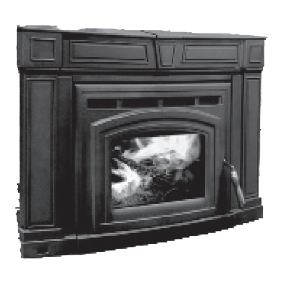
Models: 1200-C & 1700-C Insert
or the authority having jurisdiction about
restrictions and installation inspection
requirements in your area.
50-2627
Advertisement
Table of Contents

Related Manuals for Enviro 1200 Insert


Summary of Contents for Enviro 1200 Insert
- Page 1 11,479 to 34,196 BTU per hour for the 1200 and from 9,425 to 31,780 BTU per hour for the 1700. OMNI-Test Laboratories, Inc, Report # 268-S-06b-2 50-2627 Version Française: www.enviro.com/fr.html...
-
Page 2: Table Of Contents
Removal of Cast Side Panels..............26 Removal of Cast Bottom..............26 Removal of Cast Side Bracket...............27 Removal of Fan Assembly..............27 Door Latch Adjustment...............28 Parts Diagram....................29 Parts List......................30 Rating Label....................31 Electrical shock Label..................32 Warranty......................33 Installation Data Sheet..................34 Thank you for purchasing your Enviro Fireplace. -
Page 3: Safety Precautions
Safety Precautions FOR SAFE INSTALLATION AND OPERATION OF YOUR “ENVIRO” WOOD STOVE, PLEASE CAREFULLY READ THE FOLLOWING INFORMATION: ● Please read this entire manual before you install and use your new wood stove. Failure to follow instructions may result in property damage, bodily injury or even death. Be aware that local Codes and Regulations may override some items in this manual. -
Page 4: Operating Instructions
Wear gloves when handling damaged glass door assembly to prevent personal injury. When the glass door assembly is being transported, it must be wrapped in newsprint and tape and/or a strong plastic bag. The glass must be purchased from an ENVIRO dealer. No substitute materials are allowed. FIRE EXTINGUISHER AND SMOKE DETECTION: All homes with a solid fuel burning stove should have at least one fire extinguisher in a central location known to all in the household and a smoke detection device in the room containing the stove. -
Page 5: Building Your Fire
Operating Instructions CREOSOTE - ITS FORMATION AND NEED FOR REMOVAL: When wood is burned slowly, it may produce tar and other organic vapors, which combine with expelled moisture to form creosote. The creosote vapors condense in the relatively cool chimney of a slow-burning fire. - Page 6 Operating Instructions d) Regulate the heat output of the stove by adjusting the air controls to allow a larger fire and vice versa. A short period of experimentation with the control settings will allow you to regulate the heat output to keep your home comfortable.
- Page 7 Operating Instructions f) Fully open the air controls of the wood stove and close the door until it is slightly open, allowing for much needed air to be introduced into the firebox. Never leave the door fully open, as sparks from the kindling may fly out of the stove, causing damage or injury.
- Page 8 Operating Instructions 6. Is it normal for soot to cover the glass at the beginning of a fire? Your stove has been built with an air-wash system that will help keep the glass clear when the firebox has reached a good operating temperature and has a good draft. Normally, a hot stove will keep the glass clean, but if you must clean the glass, use a soft cloth with no abrasive and clean only when the unit is cold.
-
Page 9: How It Works
Operating Instructions Operating Instructions How it Works : ORK S Exhaust Smoke " Ceramic baffle; reflects heat down Convection Heat to burn the particles in the smoke. Primary air; window air wash (cooler air to Secondary air tubes; keep the glass clean). creates a second burn on the particles in the smoke for a more efficient... -
Page 10: Specifications
Cold chimney temperatures create creosote. eneral peciFicationS Table 1: 1200-C & 1700-C General Information. Model 1200 Insert 1700 Insert 31⅝ in x 18¼ in 31⅝ in x 22¾ in Minimum Install Width x Depth... -
Page 11: Clearances To Combustibles - 1200-C Insert
Specifications - 1200-c i learanceS omBuStiBleS nSert Table 2: 1200-C Insert Clearance to Combustibles. A Minimum clearance to an unshielded side wall 14 in (254 mm) B Minimum clearance to an unshielded 8” (203 21 in (533 mm) mm) mantel C Minimum top facing (protruding ¾”... -
Page 12: Clearances To Combustibles - 1700-C Insert
Specifications - 1700-c i learanceS omBuStiBleS nSert Table 5: 1700-C Insert Clearance to Combustibles. Minimum clearance to an unshielded side 14 in (254 mm) wall Minimum clearance to an unshielded 8” 24 in (610 mm) (203 mm) mantel Minimum top facing (protruding ¾” 19.5 in (495 mm) [19 mm]) clearance Minimum side facing (protruding ¾”... -
Page 13: Dimensions - 1200-C Insert
Specifications - 1200-c i imenSionS nSert... -
Page 14: Dimensions - 1700-C Insert
Specifications - 1700-c i imenSionS nSert... -
Page 15: Installation
Installation Failure to follow these instructions carefully could cause personal injury or property damage. emoval allet • r emove the bricks form the unit before starting. • Remove the two lag bolts (shown in Figure 6) that secure the unit to the pallet from inside the firebox. -
Page 16: Masonry Fireplace Installation
Installation aSonrY ireplace nStallation Unless you are experienced, we recommend installation by your dealer or a professional installer. Install only in a masonry fireplace with a good-condition chimney at least 15 ft (4.6 m) high, both of which have been constructed in accordance with the building code. Refer to Tables 4 and 7 for minimum masonry fireplace dimensions. - Page 17 Installation The flue collar is removable for installations into fireplaces with low openings. A) Remove the rear two (2) secondary air tube and C-Cast Ceramic Baffles, if installed (see ). Remove the eraMic affLe nstaLLation secondary air tubes by placing a screwdriver (any style except flat head) into one of the air holes and tapping it with a hammer/mallet to the left.
-
Page 18: Surround Panel Sealed Installation For Usa Only
Installation Leveling Legs Figure 14: Removable flue collar in place. Figure 15: Leveling legs. 3. There are four (4) leveling legs (shown in Figure 15), two (2) on each side, one at the back and one at the front of the unit. Adjust the legs using a ⅜” wrench to ensure the unit is stable. 4. -
Page 19: Modifications For Installation With
Installation uSa o nStallation Sing lock late If this unit is to be installed into a masonry fireplace or a zero- clearance fireplace with a direct connection you must install a non-combustible seal-off device such as a block-off plate or damper adapter. - Page 20 Installation the fireplace opening. Remove the template and cut a 6¼” diameter hole centered on this mark. 4. Using the template make the block-off plate of 24 Stainless steel chimney gauge or thicker steel. Drill two (2) holes in each connector must extend flange for mounting the plate.
-
Page 21: Model 1200-C Brick Placement & Tube Locations
Installation 1200-c B & t odel rick lacement ocationS COMPLETE THE STOVE AND CHIMNEY INSTALLATION BEFORE INSTALLING BRICKS. 1. Place the three (3) full size bricks along each side of the firebox and one (1) full size brick on either side of the back of the firebox. -
Page 22: Model 1700-C Brick Placement & Tube Locations
Installation 1700-c B & t odel rick lacement ocationS COMPLETE THE STOVE AND SMOKE PIPE INSTALLATION BEFORE PLACING THESE BRICKS. 1. Place the four (4) full size bricks along each side of the firebox and one (1) full size brick on either side of the back of the firebox. -
Page 23: C-Cast Ceramic Baffle Installation
Installation eramic aFFle nStallation 1. Slide the right C-Cast Ceramic Baffle in over the secondary air tubes at the top of the firebox. The tab must be on the top and pointing towards the center and the smooth side is to face down. 2. -
Page 24: Fan Wiring Diagrams
Installation iring iagram This appliance, when installed, must be electrically connected and grounded in accordance with local codes or in the absence of local codes, with the current CSA C22.1 CANADIAN ELECTRICAL CODE. Part 1, SAFETY STANDARDS FOR ELECTRICAL INSTALLATIONS, or THE NATIONAL ELECTRICAL CODE ANSI / NFPA 70 in the USA. -
Page 25: Disassembly
Disassembly CAUTION: ENSURE POWER CORD IS UNPLUGGED AND UNIT IS COLD BEFORE ATTEMPTING ANY DISASSEMBLY. emoval Figure 25: Removal of Cast Top Parts 1. Remove the three piece cast top from the unit by lifting up and forward. (For re-assembly, ensure that slots in the brackets are fully seated on the bolts) 2. -
Page 26: Removal Of Cast Side Panels
Disassembly emoval anelS 1. Lift cast sides straight up, then forward to remove. If sides are not moving, loosen (but do not remove) the three 1/4-20 screws on the side casting using a 3/8” wrench. 2. The Fan Controller assembly is mounted to Left Side Cast. -
Page 27: Removal Of Cast Side Bracket
Disassembly emoval racket 1. Use a 3/8” socket to remove the four screws holding the cast side mounting bracket to the firebox. 2. Lift the bracket up and out to remove it. Right Side Left Side Figure 29: Lower Front Casting Removal emoval SSemBlY 1. -
Page 28: Door Latch Adjustment
Disassembly atch djuStment Over time as the door gasket fully compresses to the face of the firebox, it may be necessary to adjust the door latch position to maintain a tight seal. Signs that the door latch may need adjusting are if the door handle feels overly loose when closed, or if you notice wood is being burnt faster than normal. -
Page 29: Parts Diagram
Parts Diagram... -
Page 30: Parts List
Parts List Parts List Cabello 1200/1700 Reference # Description Part # 120 CERAMIC FAN TEMP SENSOR (ALL MODELS) EC-001 FPI BURNER SWITCH EC-026 WOOD INSERT FAN CONTROLLER (75V) 115V EC-039 DOMESTIC POWER CORD (115V) EC-042 HEYCO STRAIN RELIEF EC-044 WOODSTOVE DOOR GASKET (7FT) EF-168 EFW GLASS WITH TAPE 10-000... -
Page 31: Rating Label
Rating Label Adjacent wall / Mur adjacent Figure 33: Rating Label Sample... -
Page 32: Electrical Shock Label
Electrical Shock Label lectrical hock aBel located on near electrical cord DO NOT REMOVE THIS LABEL / NE PAS ENLEVER CETTE ÉTIQUETTE LISTED SOLID FUEL SPACE HEATER / IDENTIFIE COMME UN FOYER A COMBUSTIBLE SOLIDE LISTED SO ATTENTION! DANGER! DANGER Risque de choc électrique. -
Page 33: Warranty
Exclusions conditions herein set forth, this product against defects in material and workmanship An expanded list of exclusions is available at www.enviro.com/help/warranty.html during the specified warranty period starting from the date of original purchase at retail. This warranty does not cover: In the event of a defect of material or workmanship during the specified warranty period, ƒ... -
Page 34: Installation Data Sheet
NAME OF INSTALLER: SERIAL NUMBER:___________________________ _________________________________________ DATE OF PURCHASE: ______________ (dd/mm/yyyy) ADDRESS: DATE OF INSTALLATION:___________ (dd/mm/yyyy) _________________________________________ _________________________________________ INSTALLER’S SIGNATURE: _________________________________________ _________________________________________ PHONE:___________________________________ MANUFACTURED BY: SHERWOOD INDUSTRIES LTD. 6782 OLDFIELD RD. SAANICHTON, BC, CANADA V8M 2A3 www.enviro.com April 25, 2013 C-13851...
Need help?
Do you have a question about the 1200 Insert and is the answer not in the manual?
Questions and answers