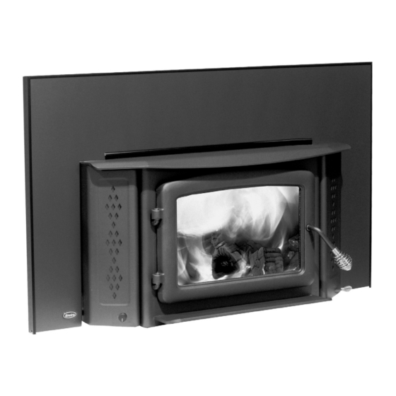
Enviro Kodiak 1200 Fireplace Freestanding Owner's Manual
Enviro - sherwood industries ltd. wood stove owner's manual
Hide thumbs
Also See for Kodiak 1200 Fireplace Freestanding:
- Owner's manual (58 pages) ,
- Owner's manual (56 pages) ,
- Owner's manual (55 pages)
Table of Contents
Advertisement
Quick Links
SHERWOOD INDUSTRIES IS AN ENVIRONMENTALLY RESPONSIBLE COMPANY. THIS MANUAL IS PRINTED ON RECYCLED PAPER.
PLEASE KEEP THESE INSTRUCTIONS FOR FUTURE REFERENCE
OWNER'S MANUAL
Models: 1200 & 1700 Insert and 1200 & 1700 Fireplace Freestanding
Contact your local building or fire officials, or the authority having jurisdiction
about restrictions and installation inspection requirements in your area.
PLEASE READ THIS ENTIRE MANUAL BEFORE INSTALLATION AND USE OF THIS WOOD
BURNING ROOM HEATER. FAILURE TO FOLLOW THESE INSTRUCTIONS COULD RESULT
IN PROPERTY DAMAGE, BODILY INJURY OR EVEN DEATH.
O- T L
Tested &
Beaverton
Listed By
Oregon USA
C
OMNI-Test Laboratories, Inc,
Kodiak
B Y : S H E R W O O D I N D U S T R I E S L T D
This heater meets the U. S. Environmental Protection Agencies
emission limits for wood heaters sold after July 1st, 1990.
Under specific conditions this heater has been shown to deliver
heat at rates ranging from 11,479 to 34,196 BTU per hour for
the 1200 and from 9,425 to 31,780 BTU per hour for the 1700.
Wood Stove
50-1040
Advertisement
Table of Contents


Need help?
Do you have a question about the Kodiak 1200 Fireplace Freestanding and is the answer not in the manual?
Questions and answers