Enviro Kodiak 1200 Owner's Manual
Insert and fireplace freestanding
Hide thumbs
Also See for Kodiak 1200:
- Owner's manual (50 pages) ,
- Owner's manual (58 pages) ,
- Owner's manual (56 pages)
Table of Contents
Advertisement
SHERWOOD INDUSTRIES IS AN ENVIRONMENTALLY RESPONSIBLE COMPANY. THIS MANUAL IS PRINTED ON RECYCLED PAPER.
PLEASE KEEP THESE INSTRUCTIONS FOR FUTURE REFERENCE.
OWNER'S MANUAL
Models: 1200 & 1700 Insert and 1200 & 1700 Fireplace Freestanding
INSTALLER: Leave this manual with the wood stove.
CONSUMER: Retain this manual for future reference.
Contact your local building or fire officials, or the authority having jurisdiction
about restrictions and installation inspection requirements in your area.
PLEASE READ THIS ENTIRE MANUAL BEFORE INSTALLATION AND USE OF THIS WOOD
BURNING ROOM HEATER. FAILURE TO FOLLOW THESE INSTRUCTIONS COULD RESULT
IN PROPERTY DAMAGE, BODILY INJURY OR EVEN DEATH.
O- T L
Tested &
Portland
Listed By
Oregon USA
C
US
OMNI-Test Laboratories, Inc,
Report # 268-S-01-2, 268-S-04b-2
Report # 268-S-06b-2
Report # 268-S-05-2, 268-S-06-2
Version Française: www.enviro.com/fr.html
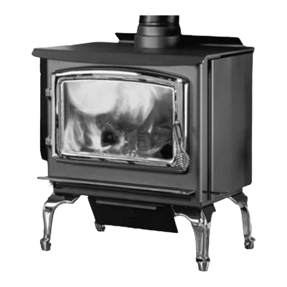
Kodiak
Wood Stove
B Y : S H E R W O O D I N D U S T R I E S L T D
This heater meets the U. S. Environmental Protection Agencies emission limits
for wood heaters sold after July 1st, 1990. Under specific conditions this heater
has been shown to deliver heat at rates ranging from 11,479 to 34,196 BTU per
hour for the 1200 and from 9,425 to 31,780 BTU per hour for the 1700.
50-1040
Advertisement
Table of Contents

Related Manuals for Enviro Kodiak 1200


Summary of Contents for Enviro Kodiak 1200
-
Page 1: Wood Stove
11,479 to 34,196 BTU per OMNI-Test Laboratories, Inc, hour for the 1200 and from 9,425 to 31,780 BTU per hour for the 1700. Report # 268-S-01-2, 268-S-04b-2 Report # 268-S-06b-2 Report # 268-S-05-2, 268-S-06-2 50-1040 Version Française: www.enviro.com/fr.html... -
Page 2: Table Of Contents
Table of Contents Safety Precautions.....................3 Operating Instructions..................4 Building Your Fire...................6 Air Control.....................9 How It Works..................10 Specifications....................11 1200 Specifications................11 1700 Specifications:................12 Clearances To Combustibles - 1200 Insert..........13 Clearances To Combustibles - 1700 Insert..........14 Clearances To Combustibles - 1200 Freestanding........15 Clearances To Combustibles - 1700 Freestanding........16 Dimensions - 1200 Insert..............17 Dimensions - 1700 Insert..............18 Dimensions - 1200 Freestanding............19... -
Page 3: Safety Precautions
Safety Precautions FOR SAFE INSTALLATION AND OPERATION OF YOUR “ENVIRO” WOOD STOVE, PLEASE CAREFULLY READ THE FOLLOWING INFORMATION: ● Please read this entire manual before you install and use your new woodstove. Failure to follow instructions may result in property damage, bodily injury or even death. Be aware that local Codes and Regulations may override some items in this manual. -
Page 4: Operating Instructions
Operating Instructions FIRST START When first installed, the chimney, firebricks and steel are cold and it usually takes several hours on a fairly high burn for them to become hot and dry enough for the stove to function well. We recommend during the unit’s first burn that a door and window are opened to vent the smoke and fumes created from the unit’s paint curing. - Page 5 Wear gloves when handling damaged glass door assembly to prevent personal injury. When the glass door assembly is being transported, it must be wrapped in newsprint and tape and/or a strong plastic bag. The glass must be purchased from an ENVIRO dealer. No substitute materials are allowed. CLEANING THE PLATED SURFACES: Painted faces should be wiped with a damp cloth periodically.
-
Page 6: Building Your Fire
Operating Instructions FAILURE TO INSPECT AND CLEAN YOUR CHIMNEY SYSTEM REGULARLY CAN RESULT IN A CHIMNEY FIRE, WHICH COULD DAMAGE THE CHIMNEY OR CAUSE A HOUSE FIRE. CHIMNEY OR RUN AWAY FIRE: 1. Call local fire department (or dial 911) 2. - Page 7 Operating Instructions They are clean and efficient but they are also very hot and gloves are useful. Keep a small steel shovel and whisk nearby for moving a log or lifting a fallen ember and for keeping the hearth clean. a) Before attempting to add fuel to the stove, OPEN the damper control fully by pulling it all the way out.
- Page 8 Operating Instructions 2. What type of wood is best to use as firewood? Both hardwood and softwood burn well in this stove. Both woods contain about 8,000 BTU/lb (18,570 KJ/Kg), but hardwood is generally more dense, will weigh more per cord, and burns a little slower and longer.
-
Page 9: Air Control
Operating Instructions 8. What can cause a poor draft? The most common factors for poor draft are: a) Air supply b) Environmental conditions c) Cold chimney temperature d) Poor chimney installation and maintenance e) Atmospheric pressure a) Air supply – Inside the home, normal household appliances such as clothes dryers and forced-air furnaces compete for air, resulting in air starvation to the fire. -
Page 10: How It Works
Operating Instructions orks Smoke " Ceramic baffle; Primary air; reflects heat down window airwash. to burn up smoke. Secondary air tubes; Pilot air. creates a secondary burn on the particles in the smoke. Dry seasoned wood Slider plate; used for air flow control. Intake air. -
Page 11: Specifications
Specifications 1200 s peCiFiCAtions Table 1: 1200 General Information. Model 1200 Freestanding 1200 Insert Flat Top Step Top 27¾” x 21½” Width x Depth 25” x 22 ” (635 mm x 570 mm) (705 mm x 546 mm) 28 ¼” 31 ¼”... -
Page 12: 1700 Specifications
Specifications 1700 s peCiFiCAtions Table 2: 1700 General Information. Model 1700 Freestanding 1700 Insert Flat Top Step Top 27¾” x 26” Width x Depth 25” x 26 ” (635 mm x 684 mm) (705 mm x 660 mm) 28 ¼” 31 ¼”... -
Page 13: Clearances To Combustibles - 1200 Insert
Specifications - 1200 i leArAnCes omBustiBles nsert Table 3: 1200 Insert Clearance to Combustibles. A Minimum clearance to an unshielded side wall 10” (254 mm) B Minimum clearance to an unshielded 8” (203 21” (533 mm) mm) mantel C Minimum top facing (protruding ¾” [19 mm]) 17½”... -
Page 14: Clearances To Combustibles - 1700 Insert
Specifications - 1700 i leArAnCes omBustiBles nsert Table 6: 1700 Insert Clearance to Combustibles. Minimum clearance to an unshielded side wall 10” (254 mm) Minimum clearance to an unshielded 8” (203 24” (610 mm) mm) mantel Minimum top facing (protruding ¾” 19½”... -
Page 15: Clearances To Combustibles - 1200 Freestanding
Specifications - 1200 F leArAnCes omBustiBles reestAnding MAINTAIN THESE MINIMUM CLEARANCES TO UNSHIELDED COMBUSTIBLES* Adjacent wall Alcove Back wall Back wall Front Front Front Hearth Alcove Table 9: 1200 Freestanding Clearance to Combustibles. Single Wall Pipe Double Wall Pipe** Double Wall Pipe Top vent out back with Heat Efficiency wall with min. -
Page 16: Clearances To Combustibles - 1700 Freestanding
Specifications - 1700 F leArAnCes omBustiBles reestAnding MAINTAIN THESE MINIMUM CLEARANCES TO UNSHIELDED COMBUSTIBLES* Adjacent wall Alcove Back wall Back wall Front Front Front Hearth Alcove Table 10: 1700 Freestanding Clearance to Combustibles. Single Wall Pipe Double Wall Pipe** Double Wall Pipe Top vent out back with Heat Efficiency wall with min. -
Page 17: Dimensions - 1200 Insert
Specifications - 1200 i imensions nsert " (683mm) " (574mm) " (566mm) " (705mm) " (860mm) " (516mm) " (1171mm) Min 13 " (337mm) Max 14 " (380mm) Regular Surround " (709mm) 5" " Oversized (127mm) (419mm) Surround " (709mm) "... -
Page 18: Dimensions - 1700 Insert
Specifications - 1700 i imensions nsert " (684mm) " (566mm) " (705mm) " (860mm) " (1171mm) " (630mm) Min. 17 " (452mm) Max. 19 " (495mm) Regular Surround " (709mm) 21" 5" Oversized (533mm) (127mm) Surround " (709mm) " (484mm) "... -
Page 19: Dimensions - 1200 Freestanding
Specifications - 1200 F imensions reestAnding " 25" (570mm) (635mm) " " " (151mm) (153mm) (419mm) " " " (402mm) (769mm) (252mm) " (760mm) " (718mm) 20" " (508mm) (98mm) 10" (254mm) Legs same height " " (375mm) (619mm) " (670mm) Figure 8: 1200 Freestanding Flat Top Dimensions. -
Page 20: Dimensions - 1700 Freestanding
Specifications - 1700 F imensions reestAnding 25" (635mm) " " (684mm) (492mm) " 21" " (151mm) (534mm) (153mm) " " (403mm) (252mm) " (769mm) " (718mm) 10" (254mm) Pedestal same height " (586mm) " " " (659mm) (622mm) (98mm) Figure 10: 1700 Freestanding Flat Top Dimensions. "... -
Page 21: Freestanding Side Dimensions For Fan Kit
Specifications reestAnding imensions 4" (104mm) " (137mm) " (69mm) " (264mm) Figure 12: 1200 Freestanding with Fan Kit Dimensions. 4" (102 mm) " (137 mm) " (263 mm) " (128 mm) Figure 13: 1700 Freestanding with Fan Kit Dimensions. -
Page 22: Installation
Installation Please read and understand these instructions before installing pedestal or ash pan and leg option. Failure to follow these instructions carefully could cause personal injury or property damage. All screws are pre-installed on the base of the unit. emovAl Allet •... -
Page 23: Legs And Ash Pan Installation - Freestanding
Installation nstAllAtion reestAnding • Place the unit on the pallet on its back. • Attach the Leg Adaptor Plate to Note: Pre-installed on 1200 the bottom of the unit using the supplied screws • 1700 Only: Attach the air channel box to the front of the pedestal spacer using two (2) T-20 screws •... -
Page 24: Modifications For Installation With
Installation ” (484 odiFiCAtions nstAllAtion witH intel nsert The Kodiak has a factory height of 19 ” (497mm) and it can be reduced to 19 ” (484mm) by modifying the unit and the surround panel. Surround Panel: 1. Fasten the Surround Spacer to the inner top surface of the Surround Panel using the four (4) T-20 screws (refer to Figure 19). -
Page 25: Hearth Protection Examples
Installation eArtH roteCtion xAmples Table 11: Examples of Hearth Pad Sizing Using Clearances From Tables 9 &10 (refer to Figures 22 & 23). Canada 1200 1700 1200 1700 (A) Minimum Width 40½” (1028mm) 36½” (926mm) 46” 50½” 42” 46½” (B) Minimum Depth (1168mm) (1283mm) (1067mm) - Page 26 Installation Optional USA 6" (152mm) Coverage CND 8" (203mm) USA 6" (152mm) CND 8" (203mm) USA 6" (152mm) CND 8" (203mm) USA 6" Door Opening (152mm) CND 8" (203mm) USA 16" (406mm) Door Opening CND 18" (457mm) Optional Optional Coverage Coverage USA 16"...
- Page 27 Installation...
-
Page 28: Outside Air Kit
Installation utside It is mandatory to use outside air for installations in mobile homes. Rear of pedestal A 4” (10.2 cm) fresh air adaptor kit is available. This adaptor can be installed either on the back pedestal or through the floor under the pedestal. -
Page 29: Chimney Installation Through Wall
Installation HimneY nstAllAtion HrougH Here are four (4) methods of combustible wall chimney connector pass-throughs. Information was provided from NFPA 211. Minimum chimney clearance to brick Method A. 12” (304.8 mm) Clearance to Combustible Wall Member: and combustibles 2 inches (50.8 mm) Using a minimum thickness 3.5”... -
Page 30: Installation Of A Listed, Factory Built Chimney - Freestanding
Installation nstAllAtion oF isted ACtorY uilt HimneY reestAnding This is a generic set of instructions; always follow the chimney manufacturer’s instructions explicitly. Also refer to “r ”. eCommended eigHts Set floor protector and stove in location in accordance with the “c - 1200 Learances oMbustibLes... - Page 31 Installation and in any area within 10 feet (304.8 cm) of the roof ridge, the chimney must be 2 feet Storm Collar Roof radiation (60.9 cm) above the ridge. Roof flashing shield (if required) Refer to Figure 30. Roof Note: Increasing the chimney Insulated chimney height above the roof may help your unit to draft better.
- Page 32 Installation AsonrY HimneY nstAllAtion reestAnding DO NOT CONNECT THIS UNIT TO OR USE IN CONJUCTION WITH ANY AIR DISTRIBUTION DUCTWORK UNLESS SPECIFICALLY APPROVED FOR SUCH INSTALLATIONS DO NOT CONNECT THIS UNIT TO A CHIMNEY FLUE SERVING ANOTHER APPLIANCE. A non-combustible floor protector is required under all freestanding units; refer to “c Learances oMbustibLes 1200 f...
-
Page 33: Masonry Fireplace Installation - Freestanding
Installation AsonrY ireplACe nstAllAtion reestAnding Unless you are experienced, we recommend installation by your dealer or a professional Rain Cap installer. Steel Plate or Flashing Chimney Support and Clamp Many venting manufacturers have listed kits available to connect a stove to a masonry fireplace. Always follow the vent manufacturer’s installation Rigid Stainless Steel Liner... - Page 34 Installation These connectors must be installed in accordance with the manufacturer’s instructions. Use only Spark arrestor cap specified components. The chimney and pipe must extend at least 10 feet (2.4 m) above the stove and Roof flashing At least 3 feet (0.9 m) above the highest point of the roof. 3 feet (914 mm) Install a rain cap with spark arrestor at the top that Roof...
-
Page 35: Masonry Fireplace Installation - Insert
Installation AsonrY ireplACe nstAllAtion nsert Unless you are experienced, we recommend installation by your dealer or a professional installer. Install only in a masonry fireplace with a good-condition chimney at least 15 ft (4.6 m) high, both of which have been constructed in accordance with the building code. Refer to Tables 5 and 8 for minimum masonry fireplace dimensions. - Page 36 Installation The flue collar is removable for installations into fireplaces with low openings. a) Remove the rear two (2) secondary air tube and C-Cast Ceramic Baffles, if installed (see c-c eraMic affLe ). Remove the secondary air nstaLLation tubes by placing a screwdriver (any style except flat head) into one of the air holes and tapping it with a hammer/mallet to USA 16”...
-
Page 37: Surround Panel Sealed Installation For Usa Only - Insert
Installation Figure 41: Removable flue collar in place. 4. Screw or nail the provided metal plate with the wording “THIS FIREPLACE HAS BEEN ALTERED TO ACCOMMODATE A FIREPLACE INSERT AND SHOULD BE INSPECTED BY A QUALIFIED PERSON Leveling Legs PRIOR TO THE RE-USE AS A CONVENTIONAL FIREPLACE.”... -
Page 38: Installation Using A Block-Off Plate For Usa Only - Insert
Installation usA o nstAllAtion sing loCk lAte nsert If this unit is to be installed into a masonry fireplace or a zero-clearance fireplace with a direct connection you must install a non-combustible seal-off device such as a block-off plate or damper adapter. By installing a block-off plate you seal the chimney, ensuring that no smoke enters the home and sealing the chimney to encourage draft. - Page 39 Installation 5. Mount the block-off plate using masonry screws in a masonry fireplace and sheet metal screws on a zero- clearance fireplace (screws Mantel need only be long enough to penetrate the first layer of Stainless steel chimney metal). Damper must connector must extend be removed 12"...
-
Page 40: Model 1200 Brick Placement & Tube Locations
Installation 1200 B & t odel riCk lACement oCAtions COMPLETE THE STOVE AND SMOKE PIPE INSTALLATION BEFORE PLACING THESE BRICKS. Tube E Tube D Tube A 1. Place the three (3) full size bricks along each side of the firebox and one (1) full size brick on either side of the back of the firebox. -
Page 41: Model 1700 Brick Placement & Tube Locations
Installation 1700 B & t odel riCk lACement oCAtions COMPLETE THE STOVE AND SMOKE PIPE INSTALLATION BEFORE PLACING THESE BRICKS. Tube C Tube B 1. Place the four (4) full size Tube A bricks along each side of the firebox and one (1) full size brick on either side of the back of the firebox. -
Page 42: Door Installation
Installation nstAllAtion Please inspect all components for damage. If damage has occurred, please contact the courier company, dealer, or distributor and have components repaired or replaced before installation. Remove the door from the packaging. Inspect the door assembly for damage. 1. -
Page 43: C-Cast Ceramic Baffle Installation
Installation erAmiC AFFle nstAllAtion 1. Slide the right C-Cast Ceramic Baffle in over the secondary air tubes at the top of the firebox. The tab must be on the top and pointing towards the center and the smooth side is to face down. 2. - Page 44 Installation Black White Black White controller temperature sensor Power Supply Figure 54: Freestanding Fan Kit Wiring Diagram. Black Fan temperature sensor Black Black Black Black Black Rocker Switch Manual White Auto controller Black Power Supply Figure 55: Fireplace Insert Fan Kit Wiring Diagram.
-
Page 45: Optional Fan Installation - Freestanding
Installation ptionAl nstAllAtion reestAnding Refer to f before installing your optional fan iring iagraM kit. 1. Remove the fan assembly from the box and inspect for any damage to the assembly. If damage is noticed call your dealer, distributor or courier company and have components replaced before installing kit. -
Page 46: Fireplace Poker Hangers - Freestanding
Installation ireplACe oker Angers reestAnding A fireplace poker can be hung at the back of the unit, on either side, when not in use. Figure 58: Fireplace poker hanging. emovAl Hrouds nsert 1. If the surround panel is installed, remove it by lifting the panel straight up then out. -
Page 47: Installation Of The Surround Panel - Insert
Installation nstAllAtion urround Anel nsert Installation of Trim: The trim set for your surround panel must be installed before installing the surround panel onto the unit, if not already done. 1. Attach one side trim to the top trim, using a corner bracket (see Figure 60) to secure pieces together. -
Page 48: Rating Label
LISTED SOLID FUEL SPACE HEATER / IDENTIFIE COMME UN FOYER A COMBUSTIBLE SOLIDE Serial No. / No. De Serié: Listed By Oregon USA XXXXXXXX Model / Modèle: Kodiak 1200 FS Kodiak 1200 Insert Kodiak 1700 FS Kodiak 1700 Insert Report/Rapport no. 268-S-04-2... -
Page 49: Parts List
Damper Handle Spring - Nickel 10-005 Door Handle Spring - Brass 10-006 Door Handle Spring - Nickel 10-007 Enviro Logo Gel Decal 50-322 1200 Leg Kit with ash drawer - Nickel 50-979 1200 Leg Kit with ash drawer - Gold 50-980... - Page 50 Parts List Reference # Description Part # Pumice Bricks - 4½” X 9” (114mm x 229mm) 50-1105 Pumice Bricks - 4½” X 4½” (114mm x 114mm) 50-1106 1200 & 1700 Cast Ash Plug 50-1120 Door Handle Assembly (Rod, Cast Latch, Brass Spring) 50-1121 1200 &...
-
Page 51: Parts Diagram - Freestanding
Parts Diagram - Freestanding... -
Page 52: Parts Diagram - Pedestals & Legs
Parts Diagram - Pedestals & Legs... -
Page 53: Parts Diagram - Fireplace Insert
Parts Diagram - Fireplace Insert Common parts are shown in Parts Diagram - Freestanding. -
Page 54: Warranty
Exclusions conditions herein set forth, this product against defects in material and workmanship An expanded list of exclusions is available at www.enviro.com/help/warranty.html during the specified warranty period starting from the date of original purchase at retail. This warranty does not cover: In the event of a defect of material or workmanship during the specified warranty period, ƒ... -
Page 55: Installation Data Sheet
NAME OF INSTALLER: SERIAL NUMBER:___________________________ _________________________________________ DATE OF PURCHASE: ______________ (dd/mm/yyyy) ADDRESS: DATE OF INSTALLATION:___________ (dd/mm/yyyy) _________________________________________ INSTALLER’S SIGNATURE: _________________________________________ _________________________________________ _________________________________________ PHONE:___________________________________ MANUFACTURED BY: SHERWOOD INDUSTRIES LTD. 6782 OLDFIELD RD. SAANICHTON, BC, CANADA V8M 2A3 www.enviro.com April 26, 2013 C-13823...
Need help?
Do you have a question about the Kodiak 1200 and is the answer not in the manual?
Questions and answers
How do you remove the door from an Enviro Kodiak wood stove insert?