Table of Contents
Advertisement
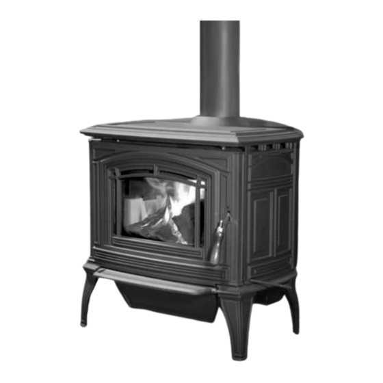
Boston 1200 FS & Boston 1700 FS
OWNER`S MANUAL
O- T L
Tested &
Portland
Listed By
Oregon USA
C
US
OMNI-Test Laboratories, Inc,
Report # 268-S-05-2, 268-S-06c-2
Report # 268-S-06b-2
Version Française: www.enviro.com/fr.html
W O O D S T O V E I N S E R T
PLEASE READ THIS ENTIRE MANUAL BEFORE INSTALLATION AND USE OF THIS
WOOD BURNING ROOM HEATER. FAILURE TO FOLLOW THESE INSTRUCTIONS
COULD RESULT IN PROPERTY DAMAGE, BODILY HARM, OR EVEN DEATH.
CONTACT YOUR BUILDING OR FIRE OFFICIALS ABOUT RESTRICTIONS AND
INSTALLATION INSPECTION REQUIREMENTS IN YOU AREA.
THIS HEATER MEETS THE 2015 U. S. ENVIRONMENTAL PROTECTION AGENCY'S CRIB-
WOOD EMISSION LIMITS FOR WOOD HEATERS SOLD AFTER MAY 15, 2015.
SPECIFIC CONDITIONS THIS HEATER HAS BEEN SHOWN TO DELIVER HEAT AT RATES
RANGING FROM 11,479 TO 34,196 BTU PER HOUR FOR THE 1200 AND FROM 9,425 TO
31,780 BTU PER HOUR FOR THE 1700. THESE STOVES HAVE BEEN CERTIFICATION TESTED
TO STANDARDS UL-1482-11 AND ULC-S627-00. CERTIFICATION TESTING COMPLETED BY
OMNI-TEST LABORATORIES.
INSTALLER: LEAVE THIS MANUAL WITH THE WOOD STOVE.
CONSUMER: RETAIN THIS MANUAL FOR FUTURE REFERENCE.
UNDER
50-2439
Advertisement
Table of Contents

Related Manuals for Enviro Boston 1200 FS


Summary of Contents for Enviro Boston 1200 FS
- Page 1 Boston 1200 FS & Boston 1700 FS W O O D S T O V E I N S E R T OWNER`S MANUAL PLEASE READ THIS ENTIRE MANUAL BEFORE INSTALLATION AND USE OF THIS WOOD BURNING ROOM HEATER. FAILURE TO FOLLOW THESE INSTRUCTIONS COULD RESULT IN PROPERTY DAMAGE, BODILY HARM, OR EVEN DEATH.
-
Page 2: Table Of Contents
Table of Contents Safety Precautions.....................3 Efficiencies and Emissions...................4 Operating Instructions..................5 Building Your Fire...................7 Air Control....................10 How It Works..................11 Specifications....................12 1200 Specifications................11 1700 Specifications................13 Clearances to Combustibles - 1200............14 Clearances to Combustibles - 1700............15 Dimensions - 1200................16 Dimensions - 1700................17 Installation......................18 Removal From Pallet................18 Hearth Protection Examples..............19 Outside Air Kit..................22... -
Page 3: Safety Precautions
Safety Precautions FOR SAFE INSTALLATION AND OPERATION OF YOUR “ENVIRO” WOOD STOVE, PLEASE CAREFULLY READ THE FOLLOWING INFORMATION: ● Please read this entire manual before you install and use your new woodstove. Failure to follow instructions may result in property damage, bodily injury or even death. Be aware that local Codes and Regulations may override some items in this manual. -
Page 4: Efficiencies And Emissions
1200 oston Rates: This manual describes the installation and operation of the Enviro Boston 1200 wood heater. This heater meets the 2015 U.S. Environmental Protection Agency’s wood emission limits for wood emission limits sold after May 15, 2015. Under specific test conditions this heater has been shown to deliver heat at rates ranging from 11,500-34,000 Btu/hr. -
Page 5: Operating Instructions
Operating Instructions FIRST START When first installed, the chimney, firebricks and steel are cold and it usually takes several hours on a fairly high burn for them to become hot and dry enough for the stove to function well. We recommend during the unit’s first burn that a door and window are opened to vent the smoke and fumes created from the unit’s paint curing. - Page 6 Wear gloves when handling damaged glass door assembly to prevent personal injury. When the glass door assembly is being transported, it must be wrapped in newsprint and tape and/or a strong plastic bag. The glass must be purchased from an ENVIRO dealer. No substitute materials are allowed. FIRE EXTINGUISHER AND SMOKE DETECTION: All homes with a solid fuel burning stove should have at least one fire extinguisher in a central location known to all in the household.
-
Page 7: Building Your Fire
Operating Instructions uilding Proper operation of your stove will help to ensure safe, efficient heating. Please take a few moments to review these simple operating procedures. IMPORTANT: Please be aware when loading your stove that the air tubes in the rear are lower. 1. - Page 8 Operating Instructions e) CAUTION: DO NOT PLACE FUEL OR COMBUSTIBLE MATERIAL WITHIN SPACE HEATER INSTALLATION CLEARANCES OR WITHIN THE SPACE REQUIRED FOR CHARGING AND ASH REMOVAL. LOGS SHOULD BE KEPT IN A BIN OR CONTAINER TO REDUCE THE RISK OF LOGS ROLLING INTO THE UNIT’S CLEARANCES. f) HOW TO AVOID OVERFIRING: To avoid overfiring, do not overfill your firebox.
- Page 9 Operating Instructions longer. Cutting firewood so that it will fit horizontally, front to back, makes it easier loading and less likely for the fuel to roll on the glass. Except for a cold start, there is no need to crisis-cross the logs. Ideal length for the logs used in the 1200-C would be about 16“...
-
Page 10: Air Control
Operating Instructions a) Air supply – Inside the home, normal household appliances such as clothes dryers and forced-air furnaces compete for air, resulting in air starvation to the fire. This creates a condition in the house known as negative pressure. When a house experiences negative pressure, the combustion gases can be drawn from the chimney and into the house. -
Page 11: How It Works
Operating Instructions orks When shutting down the stove, fully open the air control. This allows the chimney temperatures to remain as high as possible for as long as possible. Cold chimney temperatures create creosote. If all of these steps are followed, there should be no visible emissions. Warning - This adjustment should not be altered for increased firing for any reason. -
Page 12: Specifications
Specifications 1200 s pEcifications Model 1200 Freestanding 30” x 25” (762 mm Width x Depth x 635 mm) 31.75” Height with legs (806mm) 16.1” x 18.25” x Fire box size 11.15” (409 mm x 464 mm (depth x width x height) x 283 mm) 1.85 feet 3 Capacity... -
Page 13: 1700 Specifications
Specifications 1700 s pEcifications Model 1700 Freestanding 30” x 29” (762 mm Width x Depth x 736 mm) 31.75” Height with legs (806mm) 20.65” x 18.25” x Fire box size 11.95” (525 mm x (depth x width x height) 464 mm x 304 mm) 2.5 feet 3 (0.0708 Capacity meter 3 ) -
Page 14: Clearances To Combustibles - 1200
Specifications - 1200 f lEarancEs omBustiBlEs rEEstanding MAINTAIN THESE MINIMUM CLEARANCES TO UNSHIELDED COMBUSTIBLES* Adjacent wall Alcove Back wall Back wall Front Front Front Hearth Alcove Table 2: 1200 Freestanding Clearance to Combustibles. Single Wall Pipe Double Wall Pipe** Top vent out back wall with min. -
Page 15: Clearances To Combustibles - 1700
Specifications - 1700 f lEarancEs omBustiBlEs rEEstanding MAINTAIN THESE MINIMUM CLEARANCES TO UNSHIELDED COMBUSTIBLES* Adjacent wall Alcove Back wall Back wall Front Front Front Hearth Alcove Table 10: 1700 Freestanding Clearance to Combustibles. Single Wall Pipe Double Wall Pipe** Top vent out back wall with min. -
Page 16: Dimensions - 1200
Specifications - 1200 f imEnsions rEEstanding 25.00" (635mm) 22.25" (565mm) 5.50" 30.00" (140mm) (762mm) 10.00" (254mm) 16.00" (406mm) 31.75" 30.50" (806mm) (775mm) 17.00" 29.125" (432mm) (740mm) Sherwood Industries Ltd. UNLESS OTHERWISE SPECIFIED Figure 5: 1200 Freestanding Dimensions. MATERIAL ALL DIMENSIONS IN INCHES TOLERANCE General Angles... -
Page 17: Dimensions - 1700
Specifications - 1700 f imEnsions rEEstanding 29.00" (737.00 mm) 26.00" (660 mm) 30.00" 4.75" (762 mm) (121 mm) 10.00" 16.00" (254 mm) (406 mm) 30.5" (775 mm) 17.00" 29.125" (432 mm) (740 mm) Figure 5b: 1700 Freestanding Step Top Dimensions. -
Page 18: Installation
Installation Emoval allEt • Remove the screws which are securing the shipping brackets to the unit. • Remove the lag bolts and discard the brackets. Figure 6: Bolts to remove. -
Page 19: Hearth Protection Examples
Installation EartH rotEction xamplEs Table 11: Examples of Hearth Pad Sizing Using Clearances From Tables 9 &10 (refer to Figures 22 & 23). Canada 1200 1700 1200 1700 (A) Minimum Width 40½” (1028mm) 36½” (926mm) 46” 50½” 42” 46½” (B) Minimum Depth (1168mm) (1283mm) (1067mm) - Page 20 Installation USA 6" (152mm) CND 8" (203mm) USA 6" (152mm) CND 8" (203mm) Door Opening USA 16" (406mm) CND 18" (457mm) Figure 7: General Parallel Installation (refer to Tables 11 & 12). Optional Coverage USA 6" (152mm) CND 8" (203mm) USA 6"...
- Page 21 Installation...
-
Page 22: Outside Air Kit
Installation utsidE It is mandatory to use outside air for installations in mobile homes. A 4” (10.2 cm) fresh air adaptor kit is available. This kit can be installed on Rear of Ash Box the back of the Ash Box. If outside air is to be used in conjunction with the convection fan kit, there is a separate outside air adapter which connects to the bottom of the Ash Box. -
Page 23: Chimney Installation Through Wall
Installation HimnEy nstallation HrougH Here are four (4) methods of combustible wall chimney connector pass-throughs. Information was provided from NFPA 211. Minimum chimney clearance to brick Method A. 12” (304.8 mm) Clearance to Combustible Wall Member: and combustibles 2 inches (50.8 mm) Using a minimum thickness 3.5”... -
Page 24: Installation Of A Listed, Factory Built Chimney
Installation nstallation of istEd actory uilt HimnEy This is a generic set of instructions; always follow the chimney manufacturer’s instructions explicitly. Also refer to “r ”. EcommEndEd EigHts Set non combustible floor protector and stove in location in accordance with the “C LearanCes ”. - Page 25 Installation roof ridge, the chimney must be 2 feet (60.9 cm) above the ridge. Refer to Figure 14. Storm Collar Note: Increasing the chimney Roof radiation height above the roof may Roof flashing shield (if required) help your unit to draft better. Roof This greater draft can decrease Insulated chimney...
-
Page 26: Masonry Chimney Installation
Installation asonry HimnEy nstallation DO NOT CONNECT THIS UNIT TO A CHIMNEY FLUE SERVING ANOTHER APPLIANCE. A non-combustible floor protector is required under all freestanding units; refer to “C LearanCes ”. When venting into a masonry chimney, the floor protector must be installed directly below ombustibLes the chimney vent and 2”... -
Page 27: Masonry Fireplace Installation
Installation asonry irEplacE nstallation rEEstanding Unless you are experienced, we recommend installation by your dealer or a professional Rain Cap installer. Steel Plate or Flashing Chimney Support and Clamp Many venting manufacturers have listed kits available to connect a stove to a masonry fireplace. Always follow the vent manufacturer’s installation Rigid Stainless Steel Liner... - Page 28 Installation Chimney must be removable to allow for transportation of the mobile home. Spark arrestor cap CAUTION: THE STRUCTURAL INTEGRITY OF THE MOBILE HOME FLOOR, WALL, AND Roof flashing CEILING/ROOF MUST BE MAINTAINED. At least 3 feet (914 mm) OUTSIDE AIR : Roof Connection from the stoves air intake to the outside is mandatory, (MOBILE HOMES ONLY) either...
-
Page 29: Model 1200 Brick Placement & Tube Locations
Installation 1200 B & t odEl rick lacEmEnt ocations COMPLETE THE STOVE AND SMOKE PIPE INSTALLATION BEFORE PLACING THESE BRICKS. Tube E Tube D Tube A 1. Place the three (3) full size bricks along each side of the firebox and one (1) full size brick on either side of the back of the firebox. -
Page 30: Model 1700 Brick Placement & Tube Locations
Installation 1700 B & t odEl rick lacEmEnt ocations COMPLETE THE STOVE AND SMOKE PIPE INSTALLATION BEFORE PLACING THESE BRICKS. Tube C Tube B 1. Place the four (4) full size Tube A bricks along each side of the firebox and one (1) full size brick on either side of the back of the firebox. -
Page 31: C-Cast Ceramic Baffle Installation
Installation Eramic afflE nstallation 1. Slide the right C-Cast Ceramic Baffle in over the secondary air tubes at the top of the firebox. The tab must be on the top and pointing towards the center and the smooth side is to face down. Right Ceramic Baffle 2. -
Page 32: Optional Fan Installation
Installation Black Black White Black White controller temperature sensor Power Supply Figure 24: Freestanding Fan Kit Wiring Diagram. ptional nstallation rEEstanding Refer to F before installing your iring iagram optional fan kit. 1. Remove the fan assembly from the box and inspect for any damage to the assembly. -
Page 33: Disassembly
DISASSEMBLY Emoval of idEs and To remove the cast sides, lift off the Cast Top and then unscrew the slider knob and then remove the two top bolts using a 3/8” socket. The Cast Side may then be lifted up. The door may be taken off by first lifting off the Cast Top and then removing the two bolts from the top door hinge, using a 3/8”... -
Page 34: Rating Label
Serial No. / No. De Serié: Tested & LISTED SOLID FUEL SPACE HEATER / IDENTIFIE COMME UN FOYER A COMBUSTIBLE SOLIDE Listed By Boston 1200 FPI Venice 1200 FPI 1200 KI FPI Boston 1200 FS Kodiak 1200 FS 268-S-06c-2 268-S-05-2 268-S-05-2 268-S-04b-2 268-S-04b-2 Certified for use in Canada &... -
Page 35: Parts List
Convection Blower 50-2493 FPI Fan Controller - 115V EC-039 Fan Controller Knob EC-040 Domestic power cord - 115V EC-042 Boston 1200 FS Fan Kit 50-2417 Boston 1700 FS Fan Kit 50-2572 Fresh Air Kit (for fan) 50-2440 Fresh Air Kit EF-186... -
Page 36: Parts Diagram - Freestanding
Parts Diagram - Freestanding... -
Page 37: Warranty
Sherwood Industries Ltd. (“Sherwood”) hereby warrants, subject to the terms and conditions herein set forth, this product against defects in material and workmanship An expanded list of exclusions is available at www.enviro.com/help/warranty.html during the specified warranty period starting from the date of original purchase at retail. -
Page 38: Installation Data Sheet
NAME OF INSTALLER: MODEL:___________________________________ SERIAL NUMBER:___________________________ _________________________________________ DATE OF PURCHASE: ______________ (dd/mm/yyyy) ADDRESS: DATE OF INSTALLATION:___________ (dd/mm/yyyy) _________________________________________ INSTALLER’S SIGNATURE: _________________________________________ _________________________________________ _________________________________________ PHONE:___________________________________ MANUFACTURED BY: SHERWOOD INDUSTRIES LTD. 6782 OLDFIELD RD. SAANICHTON, BC, CANADA V8M 2A3 www.enviro.com May 4, 2015 C-14623...
Need help?
Do you have a question about the Boston 1200 FS and is the answer not in the manual?
Questions and answers