Table of Contents
Advertisement
Quick Links
Advertisement
Table of Contents

Related Manuals for JAI CV-M10


Summary of Contents for JAI CV-M10
- Page 1 Progressive Scan Camera CV-M10 Operation Manual (Rev.F)
-
Page 2: Declaration Of Conformity
CV-M10BX/CV-M10RS DECLARATION OF CONFORMITY AS DEFINED BY THE COUNCIL DIRECTIVE 89/336/EEC EMC (ELECTROMAGNETIC COMPATIBILITY) WE HEREWITH DECLARE THAT THIS PRODUCT COMPLIES WITH THE FOLLOWING PROVISIONS APPLYING TO IT. EN-50081-1 EN-50082-1... -
Page 3: Table Of Contents
7.4.2. Non interlaced mode ... 10 7.5. Gamma Correction ... 10 7.6. Gain Control/RS 232C control ... 10 7.6.1. Gain control on CV-M10 ... 10 7.7. CV-M10RS Serial Interface for Controls ... 10 7.7.1. RS232C Cable Connect ... 10 8. Jumper settings ... 11 8.1. -
Page 4: General
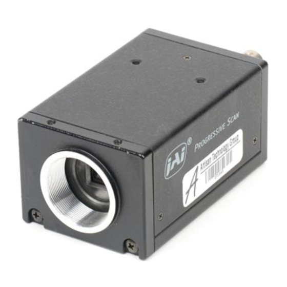
1. General The CV-M10 is a compact monochrome progressive scan camera designed for automated imaging applications. The 1/2" CCD with square pixels offers a superb image quality. The high-speed shutter function and asynchronous random trigger mode allows the camera to capture high quality images of fast moving objects. The dual tapped video output allows the camera to operate with a high frame rate. -
Page 5: Locations And Functions
4. Locations and Functions 1. Lens mount of C-mount type. *1) 2. Interline-transfer CCD sensor with on-chip micro lenses. 3. Video output 1. VS 1.0 Vp-p. *2) 4. Video output 2. VS 1.0 Vp-p. (Only in 2 :1 interlaced mode.) *2) 5. -
Page 6: Pin Assignment
5. Pin Assignment 5-1. 12-pin Multi-connector (DC-IN/SYNC.) Type: HR10A-10R-12PB-01 (Hirose) male seen from rear. Notes: *1) Signals on pin no. 6, 7 and 9 can be changed by jumper setting. See "8. Jumper Settings" for more information. *2) In Edge Pre-select and Pulse Width Control mode do not input ext. VD signal. 5.2. -
Page 7: Functions And Operation
6. Functions and Operation Apart from the standard continuous operation, the CV-M10 features two external asynchronous trigger modes, Edge Pre- select and Pulse Width Control mode. These 2 external trigger modes can operate with either H reset or H non-reset. In Edge Pre-select and H reset, the internal HD is reset on the falling edge of the trigger and the exposure starts. -
Page 8: External Trigger Mode
6.3. External Trigger Mode External trigger mode of CV-M10 allows 2 different driving modes: Edge Pre-select mode. (Asynchronous reset and exposure start by an ext. trigger) Pulse Width Control mode. (Exposure control by the low period of the ext. trigger) For both there are two trigger modes. -
Page 9: Timing Diagram For Edge Pre-Select
The resulting video signal will start to be read out after the trigger rising edge. The WEN pulse indicates the start of valid video signal. Refer to timing charts for details. A new trigger pulse must not be applied before the video read out has been finished. To use this mode: Set: SW1-4 on BX rear to OFF for random trigger. -
Page 10: Timing Diagram For Pulse Width Control
CV-M10BX/CV-M10RS 6.5. Timing diagram for Pulse Width Control Pulse width control mode (H Reset) Pulse width control mode (H Non Reset) - 7 -... -
Page 11: Mode Settings
CV-M10BX/CV-M10RS 7. Mode Settings 7.1. Mode Setting by Switch The mode setting switch SW1 on rear for CV-M10BX and CV-M10RS is different for switch SW1-1 to SW1-3 and SW1-7 to SW1- 8. For BX the shutter values can be selected in 3 ranges depending of the internal SW1 on the PK 8206 board. The switch select between Normal, High speed or Low speed. -
Page 12: Shutter Time Select
The shutter select is for CV-M10BX done with the internal SW1 on PK8206 and SW1 on rear. For CV-M10 RS only the normal shutter range can be selected by the SW1 on rear. The high speed and low speed range can only be selected by RS 232C. -
Page 13: Non Interlaced Mode
By shift to the low speed range it can take up to 20 sec. before the camera operates correctly. 7.7. CV-M10RS Serial Interface for Controls The RS-232C serial interface specification for CV-M10 is: 9600 Baud, 8 data bit, 1 start bit, 1 stop bit, and no parity. Functions, which can be controlled by the RS-232C interface, are: Shutter speed All shutter times as shown in 7.2.2... -
Page 14: Jumper Settings
8. Jumper settings Switch off the power before making any mode or jumper settings. The following modes are available with jumper setting: Input/Output Mode of HD/VD signal. (HD/VD input is factory setting) Termination of HD/VD input. (75 ohm is factory setting.) Trigger input termination. -
Page 15: Locations Of Jumper
8.6. Locations of Jumper Jumpers positions are shorted with a 0 ohm resistor or by a soldering between the 2 points. To remove the solder tin from a jumper position, use a special tin remover such as desolder wick. 8.6.1. Location of Jumper on PK8189A On this board the jumpers for HD/VD input, output and 75ohm termination are found. -
Page 16: Location Of Jumper For Cv-M10Bx On Pk8206A
8.6.3. Location of Jumper for CV-M10BX on PK8206A Jumpers for selecting random trigger modes for CV-M10BX. It is edge pre-select, pulse width control, H reset and H non- reset. Jumper for trigger input 75 ohm termination is also found here. 8.6.4. -
Page 17: Internal Adjustments On Bx
9. Internal adjustments on BX For CV-M10BX there are internal potentiometers for adjusting the two video outputs. Do not touch these adjustments unless you are familiar with video camera adjusting. The potentiometers are found on the PK8206A board in CV-M10BX. For CV-M10RS the same adjustments can be done via RS232C with the camera control tool. -
Page 18: Cv-M10Rs Camera Control Tool
CV-M10BX/CV-M10RS 10. CV-M10RS Camera Control Tool A camera control tool for CV-M10RS is available. It runs under Windows 98 and NT. After installation a bar is shown on the screen. From here windows for each function group can be opened for camera control. -
Page 19: Levels Window
CV-M10BX/CV-M10RS 10.5. Levels Window 10.6. Files and Camera 10.7. Communication Window - 16 -... -
Page 20: External Appearance And Dimensions
CV-M10BX/CV-M10RS 11. External Appearance and Dimensions Unit : mm (inch) - 17 -... -
Page 21: Specifications
12. Specifications Model CV-M10 CCD Sensor 1/2" Interline-Transfer Type Image Area 6.4mm (H) x 4.8mm (V) Number of Elements 659(H) x494(V) EIA/VGA corresponded782(H) x 582(V) CCIR Cell Size 9.9 m(H) x 9.9 m(V) Scanning System 1) Non-interlace read-out to scan full 525 lines in 1/30 sec (EIA) -
Page 22: Appendix
(shown as white dots) may appear on the video monitor screen. 13.3. References 1. This manual can and datasheet for CV-M10 can be downloaded from www.jai.com 2. Camera control software can be downloaded from www.jai.com 3. Specifications for the EIA CCD sensor ICX 074AL can be found on www.jai.com 4. -
Page 23: Users Record
11. User’s Record Camera type: Revision: Serial No. Users Mode Settings Users Modifications 15. Index No index. CV-M10BX/CV-M10RS CV-M10BX/CV-M10RS CCIR/EIA (Revision F) - 20 -... - Page 24 Fax +45 4491 8880 Phone +81 45 933 5400 www.jai.com Fax +81 45 931 6142 www.jai-corp.co.jp JAI America, Inc., USA Suite 450 23046 Avenida de la Carlota Laguna Hills, CA 92653 Phone +1 949 472 5900 Fax +1 949 472 5908...
Need help?
Do you have a question about the CV-M10 and is the answer not in the manual?
Questions and answers