
Related Manuals for Extron electronics SW2 RGBHV


Summary of Contents for Extron electronics SW2 RGBHV
- Page 1 SW RGB and SW YUV A Series Wideband and Component Video and Audio Switchers 68-648-01 Rev. C Printed in USA 09 04...
- Page 2 Precautions Safety Instructions • English Warning This symbol is intended to alert the user of important operating and maintenance Power sources • This equipment should be operated only from the power source indicated on the product. This equipment is intended to be used with a main power system with a grounded (servicing) instructions in the literature provided with the equipment.
- Page 3 Quick Start — SW RGB and YUV A Switchers Installation Step 6 — Audio Outputs SW2 RGBHV A / SW4 RGBHV A / SW6 RGBHV A: Step 1 — Remove power Cable audio models for stereo audio output (6). Turn off power to the input and output devices, SW6 YUV A: Connect a digital audio device to this and remove the power cords from them.
- Page 4 Switch inputs in normal switch mode Press and release the desired input button. Adjust audio level (SW2 RGBHV A / SW4 RGBHV A / SW6 RGBHV A only) Press A. Press and release the desired input button.
-
Page 5: Table Of Contents
Switcher Operations ......................3-4 Power ..........................3-4 Switching inputs ........................ 3-4 Audio gain and attenuation (SW2 RGBHV A, SW4 RGBHV A, and SW6 RGBHV A only) .. 3-4 ................3-5 Example — Adjusting the audio level single input .................. 3-7 Audio level reset —... - Page 6 Table of Contents, cont’d Chapter 4 • Remote Control ....................4-1 Simple Instruction Set ...................... 4-2 Host-to-switcher instructions .................... 4-2 Switcher-initiated (unsolicited) messages ................ 4-3 Error responses ........................4-3 Timeout ..........................4-3 Using the Command/Response table ................4-3 Symbol definitions ......................
-
Page 7: Chapter 1 • Introduction
SW RGB and YUV A Switchers Chapter One Introduction About the Switchers Features... -
Page 8: About The Switchers
The models available are: • SW2 RGBHV (two RGB video inputs) • SW2 RGBHV A (two RGB inputs and two balanced or unbalanced stereo or mono audio inputs) • SW4 RGBHV (four RGB video inputs) •... -
Page 9: Features
Features Audio switching models Inputs — These switchers input 2, 4, or 6 stereo audio signals, balanced or unbalanced, on 3.5 mm, 5-pole captive screw terminals. Outputs — The selected audio input is buffered and output, balanced or unbalanced, on a 3.5 mm, 5-pole captive screw terminal. Audio gain/attenuation —... -
Page 10: All Models
Introduction, cont’d All models Bandwidth — Bandwidth is 350 MHz (-3 dB). This high bandwidth allows the switchers to switch all of the high-resolution video signals with no loss of signal quality. Input signal sensing — The switcher continuously monitors all inputs to sense when the input signal is active or inactive. -
Page 11: Chapter 2 • Installation
SW RGB and YUV A Switchers Chapter Two Installation Installation Overview Mounting the Switcher Cabling and Rear Panel Views... -
Page 12: Installation Overview
Installation Installation, cont’d Installation Overview Install an SW RGB or SW YUV A Series switcher as follows: Turn off the input and output devices, and unplug their power cables. If desired, mount the switcher in a rack, under furniture, or through furniture. See Mounting the Switcher below. - Page 13 Use 2 mounting holes on opposite corners. False front panel uses 2 front holes. IT C IV E (2) 4-40 x 3/16" Screws D IO V & D IO IT C /S A -d B Figure 2-1 — Rack mounting an SW2 switcher Mounting Screws (2 Plcs) Drill pilot holes Each Side...
-
Page 14: Under-Furniture Mounting The Switcher
Installation, cont’d Under furniture mounting the switcher The SW2 switcher models can be mounted under a table or other horizontal surface with an optional Extron under-desk mounting kit (part #70-077-01). The SW4 and SW6 switcher models can be mounted under a table or other horizontal surface with an optional Extron 1U under-desk mounting kit (part #70-222-01). -
Page 15: Through-Furniture Mounting The Switcher
Drill 1/4" (6.4 mm) deep, 3/32" (2 mm) diameter pilot holes in the table or desk at the marked screw locations from the underside/inside (concealed side) of the furniture, where the switcher will be located. Insert the four wood screws into the pilot holes. Fasten each screw into the installation surface until just less than 1/4"... -
Page 16: Cabling And Rear Panel Views
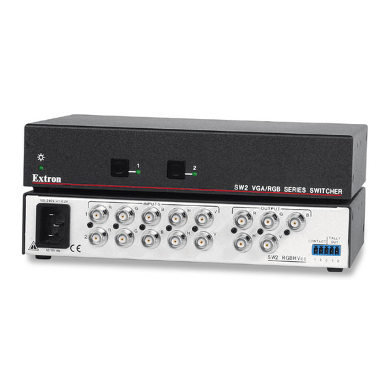
SW 2 models are in half-rack width enclosures and the rest of the models are in full- rack width enclosures. Figure 2-5 shows an SW2 RGBHV video switcher. Figure 2-6 shows an SW4 RGBHV A video and audio switcher. Figure 2-7 shows an SW6 YUV A component video and audio switcher. -
Page 17: Inputs
Digital Audio Figure 2-8 — Video input and output connections Balanced or unbalanced audio input connections (SW2 RGBHV A, SW4 RGBHV A, and SW6 RGBHV A only) — Each input has a 3.5 mm, 5-pole captive screw connector for balanced or unbalanced stereo audio input. -
Page 18: Output
Ensure that the captive screw connector is plugged into the desired input or output. Balanced or unbalanced audio output connectors (SW2 RGBHV A, SW4 RGBHV A, and SW6 RGBHV A only) — These 3.5 mm, 5-pole captive screw connectors output the selected unamplified, line level audio. -
Page 19: Remote Connection
Remote connection Remote connector — Connect a host device, such as a computer or touch panel control, or a remote contact closure device to the switcher via this 9-pin D connector (figure 2-11) for remote control of the switcher. See chapter 4, Remote Control, for definitions of the SIS commands, details on how to install and use the control software, and information on how to make a remote contact closure device. - Page 20 Installation, cont’d 2-10 SW RGB and YUV A Switchers • Installation...
-
Page 21: Chapter 3 • Operation
SW RGB and YUV A Switchers Chapter Three Operation Controls and Indicators Switcher Operations Optimizing the Audio (SW2, SW4, and SW6 RGBHV A only) Troubleshooting — If No Image Appears... -
Page 22: Controls And Indicators
LEDs. All models have an Auto/Manual mode selection switch on the rear panel. Figure 3-1 shows the front panel of an SW2 RGBHV switcher. Figure 3-2 shows the front panel of an SW6 RGBHV A switcher. These two examples show all of the combinations of button combinations and enclosure sizes that you may encounter with your particular switcher. -
Page 23: Audio Controls And Indicators
1 dB decrease in the audio level. See Audio gain and attenuation in this chapter. On the SW2 RGBHV A, this button and LED are secondary functions of the Input 1 button and LED. On the SW6 RGBHV A, this button and LED are secondary functions of the Input 5 button and LED. -
Page 24: Switcher Operations
(audio follow). Even if audio was previously broken away, audio follows the video on front panel input selection. Audio gain and attenuation (SW2 RGBHV A, SW4 RGBHV A, and SW6 RGBHV A only) Audio switchers have audio gain and attenuation adjustments. The audio level of each input can be adjusted through a range of –18 dB to +24 dB to ensure that there... -
Page 25: Example - Adjusting The Audio Level
Press and hold the Audio Conf/Save button until the Conf/ Press and hold. Save LED begins to blink, then release the Conf/Save button. The +dB and –dB LEDs display the polarity (+ or –). The lit CONF/SAVE +dB LED indicates a positive (gain) level. The lit –dB LED Conf/Save blinks. - Page 26 Operation, cont’d If the +dB and –dB LED are both lit they indicate 0 dB. Otherwise, you can determine the exact gain or attenuation using the following procedure. If one or more input LEDs are lit AND the +dB LED is/are lit, press and release the button repeatedly until the highest-numbered lit input LED goes out.
-
Page 27: Audio Level Reset - Single Input
Audio level reset — single input Reset the audio level for an input to 0 dB as follows: The switcher must be in normal (manual) mode. Press and release an input button to select an input. Press and hold the Audio Conf/Save button until the Conf/Save LED begins to blink, then release the Conf/Save button. -
Page 28: Troubleshooting - If No Image Appears
Operation, cont’d Troubleshooting — If No Image Appears Ensure that all devices are plugged in and powered on. The switcher is receiving power if the front panel Power LED (if equipped) is lit. Ensure an active input is selected on the switcher or that the switcher is in autoswitch mode. -
Page 29: Chapter 4 • Remote Control
SW RGB and YUV A Switchers Chapter Four Remote Control Simple Instruction Set Windows-Based Control Program Contact Closure Infrared Remote Control... -
Page 30: Simple Instruction Set
Remote Control Remote Control, cont’d The SW RGB and SW YUV A Series switchers can be remotely controlled via the switcher’s rear panel Remote connector (figure 4-1). Remote control devices can • A host device (such as a computer or control system) •... -
Page 31: Switcher-Initiated (Unsolicited) Messages
Switcher-initiated (unsolicited) messages When a local event, such as a front panel operation or error condition, occurs, the switcher responds by sending a message to the host. The switcher-initiated messages are listed below. (C) Copyright 2002, Extron Electronics, SW6 RGBHV {or appropriate model}, Vx.xx The switcher issues the copyright message when it first powers on. -
Page 32: Symbol Definitions
Remote Control, cont’d ASCII to HEX Conversion Table Space Symbol definitions Input and output numbers in commands may be entered as either 1-, 2-, or 3- digit numbers. All input and output numbers are specified as 3-digit numbers in the response. CR/LF (carriage return/line feed) (0x0D 0A) CR (carriage return, no line feed) •... - Page 33 Command/Response table for SIS commands (Continued) Command ASCII Command Response Additional description (host to switcher) (switcher to host) Input signal sensing Request all inputs’ status Sig• • •...• Each response is the signal status of an input, starting from input 1; n is the maximum number of inputs for this model.
-
Page 34: Windows-Based Control Program
Remote Control, cont’d Windows-Based Control Program The Universal Switcher Control Program, part #29-031-01, is compatible with MicrosSoft Windows 3.1, 3.11, 95/98, and above, and provides remote control of the following: • Input selection (including audio breakaway for models with video and audio) •... -
Page 35: Using The Help System
Using the help system For information about program features, you can access the help program in any of the following ways: • From the Extron Electronics program group, double-click on the Universal Switcher Control Program Help icon. • From within the Windows-based switcher control program, click on the Help entry on the task bar. - Page 36 Remote Control, cont’d SW RGB and YUV A Switchers • Remote Control...
-
Page 37: Appendix A • Specifications And Part Numbers
SW RGB and YUV A Switchers A ppendix A Specifications and Part Numbers Specifications Part Numbers... -
Page 38: Specifications
Switching speed ......5 ms (max.) Video input Number/signal type SW2 RGBHV/RGBHV A 2 RGBHV, RGBS, RGsB, RsGsBs, component video, S-video, composite video (or digital audio) SW4 RGBHV/RGBHV A 4 RGBHV, RGBS, RGsB, RsGsBs, component video, S-video, composite video (or digital audio) -
Page 39: Digital Audio
Sync Input type ........RGBHV (except SW6 YUV A), RGBS, RGsB, RsGsBs Output type ........RGBHV (except SW6 YUV A), RGBS, RGsB, RsGsBs Input level ........Analog or TTL, 0.5V to 5.0V p-p Output level ........5.0V p-p, unterminated, for V output; H output follows input Input impedance ...... - Page 40 4.4 cm H x 44.5 cm W x 21.6 cm D (Depth excludes connectors.) Product weight SW2 RGBHV ..... 2.4 lbs (1.1 kg) SW2 RGBHV A ....2.5 lbs (1.1 kg) All other models ....7.0 lbs (3.2 kg) Shipping weight SW2 RGBHV, SW2 RGBHV A 5 lbs (2.4 kg)
-
Page 41: Part Numbers
Part Numbers SW RGBHV switcher part numbers Switcher Part # SW2 RGBHV video switcher 60-491-01 SW2 RGBHV A video and audio switcher 60-491-21 SW4 RGBHV video switcher 60-492-01 SW4 RGBHV A video and audio switcher 60-492-21 SW6 RGBHV video switcher... -
Page 42: Assorted Connectors
Specifications, cont’d Plenum BNC-5 Mini HR Cable Part # Plenum BNC-5 Mini HR bulk, 500', 1000' 22-103-02, -03 BNC-5 RC and BNC-6 RC Cable Part # BNC-5 RC bulk, 500', 1000' 22-127-02, -03 Assorted connectors BNC connectors Part # RG6/SHR male crimp connectors, qty. 50 100-075-51 BNC Mini HR crimp connectors, qty. - Page 43 FCC Class A Notice Note: This equipment has been tested and found to comply with the limits for a Class A digital device, pursuant to part 15 of the FCC Rules. These limits are designed to provide reasonable protection against harmful interference when the equipment is operated in a commercial environment.
- Page 44 Extron Electronics, USA Extron Electronics, Europe Extron Electronics, Asia Extron Electronics, Japan 1230 South Lewis Street Beeldschermweg 6C 135 Joo Seng Road, #04-01 Daisan DMJ Building 6F Anaheim, CA 92805 3821 AH Amersfoort PM Industrial Building 3-9-1 Kudan Minami The Netherlands Singapore 368363 Chiyoda-ku, Tokyo 102-0074 Japan 714.491.1500...
Need help?
Do you have a question about the SW2 RGBHV and is the answer not in the manual?
Questions and answers