HP ProCurve 5400zl Installation And Getting Started Manual
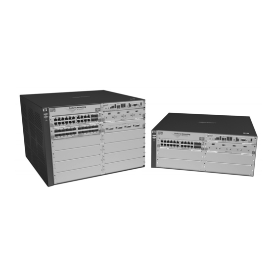
Procurve 5400xl series switches and zl power supply shelf
Hide thumbs
Also See for ProCurve 5400zl:
- Reference manual (765 pages) ,
- Installation and getting started manual (135 pages) ,
- Quickspecs (101 pages)

Related Manuals for HP ProCurve 5400zl


Summary of Contents for HP ProCurve 5400zl
- Page 1 ProCurve Series 5400zl Switches Power over Ethernet Devices www.procurve.com Installation and Getting Started Guide...
- Page 3 ProCurve Series 5400zl Switches Installation and Getting Started Guide...
- Page 4 The only warranties for HP products and services are set forth in the express warranty statements accompanying such products and services. Nothing herein should be construed as constituting an additional warranty.
-
Page 5: Table Of Contents
Contents 1 Introducing the ProCurve Series 5400zl Switches Front of the Switch ..........1-5 LEDs . - Page 6 8. (Optional) Connect a Power Supply Shelf to the switch ..........2-22 9.
- Page 7 Downloading New Code ........5-13 HP Customer Support Services ........5-13 Before Calling Support .
- Page 8 Cables ........... . B-2 Mode Conditioning Patch Cord for Gigabit-LX .
-
Page 9: D Recycle Statements
D Recycle Statements Waste Electrical and Electronic Equipment (WEEE) Statements ..D-1 Index... -
Page 11: Introducing The Procurve Series 5400Zl Switches
Introducing the ProCurve Series 5400zl Switches The ProCurve Series 5400zl Switches include the Switch 5406zl, 5412zl and their bundles, the Switch 5406zxl-48G and Switch 5412zl-96G. They are multi- port modular switches that provide Layer 3 routing features, and that feature low latency for high-speed networking. - Page 12 Introducing the ProCurve Series 5400zl Switches N o t e The 5406zl-48G bundle (J8699A) does ship with one power supply, the J8712A. Figure 1-2. ProCurve Switch 5406zl-48G bundle (J8699A) with two 10/100/1000-T zl Modules...
- Page 13 Introducing the ProCurve Series 5400zl Switches Switch 5412zl, Switch 5412zl-96G. The Switch 5412zl is available as an open 12-slot chassis (J8698A) and as the Switch 5412zl-96G bundle (J8700A) with four 24-port 10/100/1000-T zl Modules pre-installed. Figure 1-3. ProCurve Switch 5412zl (J8698A)
- Page 14 Introducing the ProCurve Series 5400zl Switches N o t e The 5412zl-96G bundle (J8700A) ships with two power supplies, the J8712A. Figure 1-4. ProCurve Switch 5412zl-96G (J8700A) See “Switch Features” on be installed in the ProCurve Series 5400zl Switches (modules available when this manual was printed).
-
Page 15: Front Of The Switch
Front of the Switch Power Locator LED and Fault LEDs Module Link and Mode LEDs with Link and Mode LEDs for each port located on each module Figure 1-5. Front of 5406zl-48G Switch This illustration shows the 5406zl-48G (J8699A), but the labeling and descrip- tions apply to all of the ProCurve Series 5400zl switches. -
Page 16: Leds
Introducing the ProCurve Series 5400zl Switches Front of the Switch LEDs As described in the next two tables, there are LEDs on the switch chassis and on the switch modules that keep you informed of the status of the switch and the network connections. - Page 17 LEDs State Meaning Mgmt A Management module is present and fault free. (green/Orange) The switch is powered off. Blinking There is a fault on the Management module. If any PoE modules are installed. (green/Orange) If no PoE modules are installed. Blinking Internal PoE fault.
- Page 18 Introducing the ProCurve Series 5400zl Switches Front of the Switch LEDs State Meaning LED Mode Select Indicates that the port Mode LEDs are displaying network activity information. (5 green LEDs) Indicates that the port Mode LEDs are lit for ports that are in Full Duplex Mode. Indicates which ports are supplying PoE power.
-
Page 19: Led Mode Select Button And Indicator Leds
LED Mode Select Button and Indicator LEDs To optimize the amount of information that can be displayed for each of the switch ports, the Series 5400zl Switches use a Mode LED for each port. The operation of this LED is controlled by the LED Mode Select button on the switch chassis, and the current selection is indicated by the mode indicator LEDs near the button. -
Page 20: Console Port
Introducing the ProCurve Series 5400zl Switches Front of the Switch • Slow Blinking = Internal PoE fault on this port. • Fast Blinking = This port is denied PoE power or has an external load fault. Mode LED: • On = PoE power is be supplied on this port •... -
Page 21: Back Of The Switch
Restoring Factory Default Configuration - When pressed with the ■ Reset button in a specific pattern, the Clear button clears any configura- tion changes you may have made through the switch console, the web browser interface, or SNMP management, and restores the factory default configuration to the switch. -
Page 22: Power Connector
Introducing the ProCurve Series 5400zl Switches Back of the Switch Power Connector The Series 5400zl Switches do not have a power switch; they are powered on when connected to an active AC power source. The Series 5400zl Switches automatically adjust to any voltage between 100-127 and 200-240 volts when using the J8712A power supply, and 200-240 volts only when using the J8713A power supply, and either 50 or 60 Hz.There are no voltage range settings required. -
Page 23: Switch Features
Switch Features The features of the Series 5400zl Switches include: 6 or 12 slots for installing any of the available Switch zl Modules. ■ Supported Modules: As of this printing, the supported zl modules include: • 24-port 10/100/1000-T zl PoE Module (J8702A) -- which can provide Power over Ethernet (PoE) power to 802.3af compliant (and some pre-standard) devices. - Page 24 ProCurve Manager—an SNMP-based graphical interface that is used to manage your entire network, included with your new switch. • Supported by ProCurve Network Manager—an HP OpenView appli- cation that accurately displays your switch on network maps and provides a graphical interface for configuring and monitoring your switch.
-
Page 25: Installing The Series 5400Zl Switches
Installing the Series 5400zl Switches The Series 5400zl Switches are easily installed. They come with an accessory kit that includes the brackets for mounting the switch in a standard 19-inch telco rack, or in an equipment cabinet. The switches have rubber feet already attached so they can be securely located on a horizontal surface. - Page 26 Installing the Series 5400zl Switches Included Parts Region Australia/New Zealand China Continental Europe Denmark Japan Switzerland United Kingdom/ Hong Kong/Singapore United States/Canada/ Mexico South Africa Taiwan Israel Thailand J a p a n P o w e r C o r d W a r n i n g J8712A J8713A 8120-5335...
-
Page 27: Installation Procedures
Installation Procedures Summary Follow these easy steps to install your switch. The rest of this chapter provides details on these steps. Prepare the installation site environment into which you will be installing the switch is properly prepared including having the correct network cabling ready to connect to the switch, and having a good location for the switch. - Page 28 Installing the Series 5400zl Switches Installation Procedures Connect the switch to a power source is mounted, plug it in to the nearby main power source. Connect a Power Supply Shelf to use a Power Supply Shelf with your switch. To do so you must connect the external power supply using the EPS cables supplied with the Power Supply Shelf.
-
Page 29: Installation Precautions
Installation Precautions Follow these precautions when installing your Series 5400zl Switch: W A R N I N G ■ Devices installed in a rack or cabinet should be mounted as low as possible, with the heaviest device at the bottom and progres- sively lighter devices installed above. - Page 30 C a u t i o n s ■ If the switch is to be shipped in a rack, use only an HP 10000 series rack and a rail mounting kit (5070-0145) for each switch. Ensure the power source circuits are properly grounded, then use the ■...
-
Page 31: Prepare The Installation Site
1. Prepare the Installation Site Cabling Infrastructure Ensure the cabling infrastructure meets the necessary network specifications. See the following table for cable types and lengths, and see appendix B, “Switch Ports and Network Cables” on Table 2-1. Port Type Cable Type 10/100/1000BASE-T For either 10, 100 Mbps or 1000 Mbps operation:... -
Page 32: Installation Location
Installing the Series 5400zl Switches Installation Procedures Port Type Cable Type 10-GbE SR Multimode fiber-optic cable designed for Gigabit Ethernet: 62.5/125 μm (core/cladding) diameter or 50/125 μm, 850 nm, low metal content, complying with the ITU-T G.652 and ISO/IEC 793-2 Type B1 standards. 9/125 μm (core/cladding) diameter, 1480 nm, 10-GbE LR low metal content, single mode fiber-optic... -
Page 33: Install Switch Modules
2. Install Switch Modules Install switch modules into the slots as shown in the illustration below. For installation details, see the instructions in the manual that comes with the module. C a u t i o n Make sure you install only ProCurve Switch zl Modules. Avoid any electrostatic discharge problems by handling the modules only by their bulkheads. - Page 34 Installing the Series 5400zl Switches Installation Procedures Insert module into the guides and slide it in until it is fully inserted. Figure 2-1. Module Being Installed in a Chassis 2-10 Open extractor handles...
- Page 35 Installing the Series 5400zl Switches Installation Procedures Use the extractor handles to seat the module completely. Then tighten the retaining screws on the module until they are secure, but do not overtighten them. Figure 2-2. Generic Chassis with Module Fully Installed 2-11...
-
Page 36: Optional) Install Another Power Supply
Installing the Series 5400zl Switches Installation Procedures 3. (Optional) Install Another Power Supply C a u t i o n The Series 5400zl switches are designed to provide continuously operating PoE power in the event of a single power supply failure with only a loss of PoE power to lower priority ports. - Page 37 C a u t i o n The switch power supplies are hot swappable; they can be installed while the switch is receiving power from the supply in the other slot. But, as indicated by the caution statement on the power supply, the supply must not be connected to AC power before being installed or removed.
- Page 38 Installing the Series 5400zl Switches Installation Procedures Once the power supply is installed, tighten the four retaining screws that hold it in place. The screws can be tightened with either a flat-bladed or Torx T-10 screwdriver. Be careful not to overtighten the screws. Figure 2-4.
-
Page 39: Verify The Switch Passes Self Test
4. Verify the Switch Passes Self Test After you have installed any modules and the optional second power supply, but before mounting the switch in its network location, you should first verify it is working properly by plugging it into a power source and verifying it passes its self test. -
Page 40: Led Behavior
Installing the Series 5400zl Switches Installation Procedures Switch Fault LED Switch Module LEDs: Link and Mode LEDs for each port Figure 2-6. Switch Fault, Module, and Chassis LEDs When the switch is powered on, it performs its diagnostic self test. The entire download, initialization, and self test process can take up to 2 minutes for a fully loaded chassis, depending on the number and type of modules installed in the switch. -
Page 41: Mount The Switch
If the ports are connected to active network devices, the Link LEDs • stay on and the Mode LEDs behave according to the mode selected. In the default mode (Activity), the Mode LEDs should flicker showing network activity on the port. •... - Page 42 Installing the Series 5400zl Switches Installation Procedures 8 mm M4 screws Figure 2-7. Attaching Brackets to the 5400zl Switch Partially install a screw into the top hole of a pair of holes that are 0.5 inches apart in each rack/cabinet upright as shown in the illustration below.
- Page 43 Installing the Series 5400zl Switches Installation Procedures lower the switch with mounting brackets onto the partially installed screws, then tighten these screws Figure 2-9. Notches in Bracket Being Installed 2-19...
-
Page 44: Horizontal Surface Mounting
Installing the Series 5400zl Switches Installation Procedures Install the other screw into the upper hole in each bracket. Tighten these screws. install and tighten the other 12-24 screws Figure 2-10. Screws in Bracket Being Installed Horizontal Surface Mounting Place the switch on a table or other horizontal surface. Use a sturdy surface in an uncluttered area. -
Page 45: Install The Grounding Wire
6. Install the Grounding Wire If a grounding wire is to be attached to the switch chassis, the grounding lug must be removed and a wire crimped to it and the grounding lug must be reinstalled. Use a #1 Phillips (cross-head) screwdriver and remove the grounding lug and two screws from the back of the switch. -
Page 46: Optional) Connect A Power Supply Shelf
Installing the Series 5400zl Switches Installation Procedures 8. (Optional) Connect a Power Supply Shelf to the switch Connect the supplied external power supply (EPS) cables to the switch and to the Power Supply Shelf. Tighten the thumb screws on all connectors to prevent any accidental disconnects. -
Page 47: Operating Characteristics Of The Eps (J8714A)
Operating Characteristics of the EPS (J8714A) The Power Supply Shelf has two EPS Ports. The EPS can provide a maximum of up to 900 watts of PoE power to each of the two EPS ports depending on which power supply is used. It is important to understand the PoE power requirements of the 5400zl Series switches because if the PoE power is not planned and implemented correctly the end devices connected to the switch ports may not receive power if an internal switch PoE power supply should... -
Page 48: Connecting The Power Supply Shelf
Installing the Series 5400zl Switches Installation Procedures Connecting the Power Supply Shelf To Power Source 5406zl Figure 2-12. Connecting the EPS to one 5406zl switch To Power Source 5406zl Figure 2-13. Connecting the EPS to two 5406zl switches Although these examples show the EPS connecting to the 5406zl switch, it can also be connected to a 5412zl switch in the same manner. -
Page 49: Connect The Network Devices
9. Connect the Network Devices The type of network connections you will need to use depends on the types of switch modules you have installed in your Series 5400zl Switch. See the documentation accompanying the modules for cabling configurations and procedures for those modules. -
Page 50: 10. (Optional) Connect A Console To The Switch
Installing the Series 5400zl Switches Installation Procedures 10. (Optional) Connect a Console to the Switch The Series 5400zl Switches have a full-featured, easy to use console interface for performing the following tasks: Monitor switch and port status and observe network activity counters ■... -
Page 51: Direct Console Access
Direct Console Access To connect a console to the switch, follow these steps: Connect the PC or terminal to the switch’s Console Port using the console cable included with the switch. (If your PC or terminal has a 25- pin serial connector, first attach a 9-pin to 25-pin straight-through adapter to the PC end of the... -
Page 52: Hot Swapping Switch Modules
Installing the Series 5400zl Switches Hot Swapping Switch Modules Hot Swapping Switch Modules The switch modules can be “hot swapped” (except for the Management Module, it is not hot swappable), that is installed or replaced while the switch is powered on (See Module Installation Notes on differ slightly, though between adding new modules to an empty slot or replacing modules with the same type, and exchanging the module with a different type. -
Page 53: Example Network Topologies
Installing the Series 5400zl Switches Example Network Topologies Example Network Topologies This section shows a few example network topologies in which the Series 5400zl Switches can be implemented. Although these examples show the 6-slot chassis, the principles are the same for the 12-slot chassis. Basic Connectivity Series 5400zl Switch Phones, APs and other peripherals... -
Page 54: Use As An Edge Switch
Installing the Series 5400zl Switches Example Network Topologies Use as an Edge Switch Trunked redundant Gigabit fiber-optic cables Series 5406zl Switch Figure 2-16. Edge Switch Configuration When your network expands and the users need to access resources beyond the edge of the local network, the Series 5400zl Switches are excellent platforms for that expansion. -
Page 55: Getting Started With Switch Configuration
Getting Started With Switch Configuration This chapter is a guide for using the console Switch Setup screen to quickly assign an IP (Internet Protocol) address and subnet mask to the switch, set a Manager password, and, optionally, configure other basic features. For more information on using the switch console and the other switch management interfaces: the web browser interface and the SNMP manage- ment tool, ProCurve Manager, please see the Management and Configuration... -
Page 56: Using The Switch Setup Screen
(the default display). The CLI prompt appears displaying the switch model number, for example: ProCurve 5400zl# At the prompt, enter the setup command to display the Switch Setup screen. The following illustration is an example of a Setup screen with default settings. - Page 57 Use the Tab key to select the Manager Password field and enter a manager password of up to 16 characters. Tab to the IP Config (DHCP/Bootp) field and use the Space bar to select the Manual option. Tab to the IP Address field and enter the IP address that is compatible with your network.
-
Page 58: Where To Go From Here
Getting Started With Switch Configuration Where to Go From Here The above procedure configures your switch with a Manager password, IP address, and subnet mask. As a result, with the proper network connections, you can now manage the switch from a PC equipped with Telnet, a web browser interface, or from an SNMP-based network management station using a tool such as ProCurve Manager. -
Page 59: Using The Ip Address For Remote Switch Management
Press a key, and you will then see the switch console command (CLI) prompt, for example (assuming there is no password): ProCurve 5400zl# Enter help or ? to see a list of commands that can be executed at the prompt. - Page 60 Getting Started With Switch Configuration Using the IP Address for Remote Switch Management ProCurve Switch 5406zl - Status: Information J8699A ProCurve Switch 5406zll Figure 3-2. Switch Web Browser Interface - Status Overview For more information on using the web browser interface, please see the Management and Configuration Guide which is on the ProCurve Web site.
-
Page 61: Replacing Components
C a u t i o n The ProCurve 5400zl Switch and its components are sensitive to static discharge. Use an antistatic wrist strap and observe all static precautions when hot swapping components. For example, connect your antistatic wrist strap to the ground point on the front of the switch, above the rightmost power supply bay. -
Page 62: Replacing Power Supplies
Replacing Power Supplies Replacing Power Supplies If your ProCurve 5400zl Switch is configured with redundant power supplies, you will not suffer any loss of traffic or performance if a power supply fails. Replace the failed component as soon as possible. One of the Internal Power LEDs on the management module will blink simultaneously with the switch Fault LED indicating which power supply failed. - Page 63 Insert the power supply into the opening. Slide it all the way in until it connects to the switch. The power supply face plate will be flush with the back face of the switch. Figure 4-2. Power Supply Installation Tighten the four retaining screws that hold it in place. Be careful not to overtighten the screws.
-
Page 64: Replacing Fan Trays
Replacing Components Replacing Fan Trays Replacing Fan Trays When a fan fails the Fan Status LED on the switch chassis will blink simultaneously with the switch Fault LED. In this case, the entire fan tray needs to be replaced. You cannot replace individual fans. The fan tray is hot swappable. -
Page 65: Replacing The Management Module
Replacing the Management Module The switch does not have to be powered off to remove the management module, however when the management module is removed all ports will lose communication. ProCurve Networking recommends replacing the Manage- ment module, flash disk and battery (on the Management module) during scheduled down time. -
Page 66: Replacing The Management Module Compact Flash Card
Replacing Components Replacing the Management Module Compact Flash Card Replacing the Management Module Compact Flash Card The Compact Flash card is the primary non-volatile storage medium located on the management module that contains both the boot software and configuration files. When a Flash card fails the Flash status LED on the management module will blink simultaneously with the switch Fault LED. -
Page 67: Replacing The Management Module Battery
Replacing the Management Module Battery The battery on the management module is used to keep time for the internal switch clock. There is no indicator LED for when the battery dies. The only indication will be the internal clock will not keep the correct time. W A R N I N G ■... - Page 68 Replacing Components Replacing the Management Module Battery Remove the old battery and dispose of properly. Insert the new battery with the lettering and the plus “+” sign facing up. Reinstall the management module into the switch. Use an equal amount of pressure and push both extractor handles closed to completely seat the module.
-
Page 69: Troubleshooting
■ ■ restoring the factory default configuration ■ downloading new code HP Customer Support Services ■ Basic Troubleshooting Tips Most problems are caused by the following situations. Check for these items first when starting your troubleshooting: ■... - Page 70 Troubleshooting Basic Troubleshooting Tips ■ Non-standard cables. Non-standard and miswired cables may cause network collisions and other network problems, and can seriously impair network performance. Use a new correctly-wired cable or compare your cable to the cable in appendix B, “Switch Ports and Network Cables” for pinouts and correct cable wiring.
- Page 71 Because the Series 5400zl Switches behave in this way (in compliance with the IEEE 802.3 standard), if a device connected to the switch has a fixed configuration at full duplex, the device will not connect correctly to the switch. The result will be high error rates and very inefficient communications between the switch and the device.
-
Page 72: Diagnosing With The Leds
Troubleshooting Diagnosing with the LEDs Diagnosing with the LEDs Table 5-1 shows LED patterns on the switch and the switch modules that indicate problem conditions. Check in the table for the LED pattern you see on your switch Refer to the corresponding diagnostic tip on the next few pages. Table 5-1. -
Page 73: Diagnostic Tips
Diagnostic Tips: Number Problem ➊ The power supplies 1. Verify the power cord is plugged into an active power source and to the switch. installed in the Ensure these connections are snug. switch are not 2. Try power cycling the switch by unplugging and plugging the power cord back in. plugged into active 3. - Page 74 Troubleshooting Diagnosing with the LEDs Number Problem ➎ The module The modules are all tested whenever the switch is powered on, or reset (through installed in the slot the Reset button on the switch, or the Boot or Reset options in the console or web that corresponds to browser interface), and when they are hot swapped (installed when the switch is the letter that is...
- Page 75 Number Problem ➐ The network port During the module self test, described in tip number 4 earlier in this table, each for which the Link network port is also tested. If the port self test fails, the individual port is not usable, LED is blinking has but the rest of the ports on the module, which have passed their self test, will experienced a self...
- Page 76 If the other procedures don’t resolve the problem, try using a different port or a different cable. Solution either a straight-through or a crossover cable can be used and the switch will automatically adjust its operation. See the “HP Auto-MDIX Feature” description on page B-6 for more information.
-
Page 77: Proactive Networking
Proactive Networking The Series 5400zl Switches have built-in management capabilities that proactively help you manage your network including: finding and helping you fix the most common network error conditions ■ (for example, faulty network cabling, and non-standard network topologies) ■ informing you of the problem with clear, easy-to-understand messages recommending network configuration changes to enhance the ■... -
Page 78: Hardware Diagnostic Tests
Troubleshooting Hardware Diagnostic Tests Hardware Diagnostic Tests Testing the Switch by Resetting It If you believe the switch is not operating correctly, you can reset the switch to test its circuitry and operating code. To reset a switch, either: ■ Unplug and plug in the power cord (power cycling) Press the Reset button on the front of the switch ■... -
Page 79: Testing Twisted-Pair Cabling
Testing Twisted-Pair Cabling If you think the cable should work but still isn’t working, it may not be compatible with the IEEE 802.3 Type 10Base-T, 100Base-TX, or 1000Base-T standards, as appropriate for the switch port type that the cable is connected to. -
Page 80: Restoring The Factory Default Configuration
Troubleshooting Restoring the Factory Default Configuration Restoring the Factory Default Configuration As part of your troubleshooting process, it may become necessary to return the switch configuration to the factory default settings. This process momen- tarily interrupts the switch operation, clears any passwords, clears the console event log, resets the network counters to zero, performs a complete self test, and reboots the switch into its factory default configuration including deleting an IP address, if one is configured. -
Page 81: Downloading New Code
The new code would be available on the ProCurve Networking Web site, www.procurve.com. HP Customer Support Services If you are still having trouble with your switch, Hewlett-Packard offers support 24 hours a day, seven days a week through the use of a number of automated electronic services. -
Page 83: Specifications
Specifications Physical Width: Depth: Height: • Switch 5406zl • Switch 5412zl Weight: • Switch 5406zl • Switch 5406zl-48G • Switch 5412zl • Switch 5412zl-96G Electrical The Series 5400zl Switches automatically adjust to any voltage between 100-127 and 200-240 volts when using the J8712A power supply, and 200-240 volts only when using the J8713A power supply, and either 50 or 60 Hz. -
Page 84: Environmental
Specifications Environmental Temperature: Relative humidity: (non-condensing) Maximum altitude: If you are installing either the J8705A or J8707A modules, or any of the X2 transceivers, the operating ambient temperature should not exceed 40°C (104°F). See transceiver specifications below. Temperature: SR Optic J8436A LR Optic J8437A ER Optic J8438A Copper J8440B... -
Page 85: Acoustic
Acoustic Switch 5400zl and 5406zl-48G: Geräuschemission LpA = 40.2 dB am fiktiven Arbeitsplatz nach DIN 45635 T.19 Noise Emission LpA = 40.2 dB in a virtual workspace according to DIN 45635 T.19 Switch 5412zl and 5412zl-96G: Geräuschemission LpA = 45.8 dB am fiktiven Arbeitsplatz nach DIN 45635 T.19 Noise Emission LpA = 45.8 dB in a virtual workspace according to DIN 45635 T.19... -
Page 86: Lasers
Specifications Lasers The following products are Class 1 Laser Products. Laser Klasse 1:The 10-GbE X2-SC SR transceiver ■ ■ The 10-GbE X2-SC LR transceiver The 10-GbE X2-SC ER transceiver ■ The following products are Class 1m Laser Products. Laser Klasse 1m: ■... -
Page 87: B Switch Ports And Network Cables
Switch Ports and Network Cables This appendix includes switch connector information and network cable information for cables that should be used with the Series 5400zl Switches, including minimum pin-out information and specifications for twisted-pair cables. N o t e Incorrectly wired cabling is the most common cause of problems for LAN communications. -
Page 88: Cables
Switch Ports and Network Cables Cables Twisted-Pair 10 Mbps Operation 100 Mbps Operation 1000 Mbps Operation Category 5 100-ohm differential 4-pair UTP or STP cable, Note on 1000Base-T Cable Requirements. The Category 5 networking cables that work for 100Base-TX connections should also work for 1000Base-T, as long as all four-pairs are connected. -
Page 89: Fiber-Optic Cables
Fiber-Optic Cables Port Type Cable Specifications 62.5/125 μm or 50/125 μm (core/cladding) Gigabit-SX diameter, graded-index 850 nm, low metal content, multimode fiber-optic cables, complying with the ITU-T G.651 and ISO/IEC 793-2 Type A1b or A1a respectively. 9/125 μm (core/cladding) diameter, graded- Gigabit-LX index 1310 nm, low metal content, single mode fiber-optic cables, complying with the... -
Page 90: Copper Cables
Switch Ports and Network Cables Port Type Cable Specifications 9/125 μm (core/cladding) diameter, 1550 nm, 10-GbE ER low metal content, single mode fiber-optic cables, complying with the ITU-T G.652 and ISO/IEC 793-2 Type B1 standards. Note: Conditioning patch cord cables are not supported for 10-GbE. 12 fiber 50/125 μm (core/cladding) diameter, OMC CX4 Fiber... -
Page 91: Mode Conditioning Patch Cord For Gigabit-Lx
Mode Conditioning Patch Cord for Gigabit-LX The following information applies to installations in which multimode fiber- optic cables are connected to a Gigabit-LX port. N o t e Mode Conditioning Patch Cord cables only apply to one Gigabit operation. Mode Conditioning Patch Cord cables are not supported for 10 Gigabit operation. -
Page 92: Installing The Patch Cord
Twisted-Pair Cable/Connector Pin-Outs The HP Auto-MDIX Feature. In the default configuration, “Auto”, the 10/100Base-TX ports on the 10/100-TX and PoE xl Modules used in the Series 5400zl Switches all automatically detect the type of port on the connected device and operate as either an MDI or MDI-X port, whichever is appropriate. - Page 93 N o t e HP Auto-MDIX was developed and shared with the IEEE for the development of the IEEE 802.3ab standard. HP Auto-MDIX and the IEEE 802.3ab Auto MDI/ MDI-X feature are completely compatible. If you connect a Series 5400zl Switch twisted-pair port to another switch or hub, which typically have MDI-X ports, the Series 5400zl Switch port automat- ically operates as an MDI port.
-
Page 94: Straight-Through Twisted-Pair Cable For 10 Mbps Or 100 Mbps Network Connections
Straight-Through Twisted-Pair Cable for 10 Mbps or 100 Mbps Network Connections Because of the HP Auto-MDIX operation of the 10/100 ports on the switches, for all network connections, to PCs, servers or other end nodes, or to hubs or other switches, you can use straight-through cables. -
Page 95: Crossover Twisted-Pair Cable For 10 Mbps Or 100 Mbps Network Connection
Crossover Twisted-Pair Cable for 10 Mbps or 100 Mbps Network Connection The HP Auto-MDIX operation of the 10/100 ports on the switches also allows you to use crossover cables for all network connections, to PCs, servers or other end nodes, or to hubs or other switches. -
Page 96: Straight-Through Twisted-Pair Cable For 1000 Mbps Network Connections
Switch Ports and Network Cables Twisted-Pair Cable/Connector Pin-Outs Straight-Through Twisted-Pair Cable for 1000 Mbps Network Connections 1000Base-T connections require that all four pairs or wires be connected. Cable Diagram Figure B-4. Straight-through Cable Diagram for 1000 Mbps Network Connection N o t e Pins 1 and 2 on connector “A”... -
Page 97: C Safety And Regulatory Statements
Safety and Regulatory Statements Safety Information WARNING Caution Grounding These are safety class I products and have protective earthing terminals. There must be an uninterruptible safety earth ground from the main power source to the product's input wiring terminals, power cord, or supplied power cord set. -
Page 98: Informations Concernant La Sécurité
Safety and Regulatory Statements Informations concernant la sécurité Informations concernant la sécurité WARNING Caution Cet appareil est un produit de classe I et possède une borne de mise à la terre. La source d'alimentation principale doit être munie d'une prise de terre de sécurité installée aux bornes du câblage d'entrée, sur le cordon d'alimentation ou le cordon de raccordement fourni avec le produit. -
Page 99: Hinweise Zur Sicherheit
Hinweise zur Sicherheit Symbol für Dokumentationsverweis. Wenn das Produkt mit diesem Symbol markiert ist, schlagen Sie bitte in der Produktdokumentation nach, um mehr Informationen über das Produkt zu erhalten. WARNING Symbol für Dokumentationsverweis. Wenn das Produkt mit diesem Symbol markiert ist, schlagen Sie bitte in der Produktdokumentation nach, um mehr Informationen über das Produkt zu erhalten. -
Page 100: Considerazioni Sulla Sicurezza
Safety and Regulatory Statements Considerazioni sulla sicurezza Considerazioni sulla sicurezza WARNING Caution Questo prodotto è omologato nella classe di sicurezza I ed ha un terminale protettivo di collegamento a terra. Dev'essere installato un collegamento a terra di sicurezza, non interrompibile che vada dalla fonte d'alimentazione principale ai terminali d'entrata, al cavo d'alimentazione oppure al set cavo d'alimentazione fornito con il prodotto. -
Page 101: Consideraciones Sobre Seguridad
Consideraciones sobre seguridad Símbolo de referencia a la documentación. Si el producto va marcado con este símbolo, consultar la documentación del producto a fin de obtener mayor información sobre el producto. WARNING Una WARNING en la documentación señala un riesgo que podría resultar en lesiones o la muerte. -
Page 102: Safety Information (Japan
Safety and Regulatory Statements Safety Information (Japan) Safety Information (Japan) -
Page 103: Safety Information (China
Safety and Regulatory Statements Safety Information (China) Safety Information (China) -
Page 104: U.s.a
Safety and Regulatory Statements EMC Regulatory Statements EMC Regulatory Statements U.S.A. FCC Class A This equipment has been tested and found to comply with the limits for a Class A digital device, pursuant to Part 15 of the FCC Rules. These limits are designed to provide reasonable protection against interference when the equipment is operated in a commercial environment. -
Page 105: Korea
Korea Taiwan Regulatory Model Identification Number For regulatory identification purposes, the ProCurve Series 5400zl Switches are assigned a Regulatory Model Number. The Regulatory Model Number for these switches is RSVLC- 0503. This regulatory number should not be confused with the marketing name (ProCurve Series 5400zl Switches), or product numbers (J8697A, J8698A, J8699A, and J8700A). -
Page 106: European Community
Safety and Regulatory Statements EMC Regulatory Statements European Community ______________________________________________________________________ Supplier's Name: Supplier's Address: declares, that the product Product Name: Product Number(s): Regulatory Model: Product Options: conforms to the following Product Specifications: Safety: EN 60950:2001 / IEC 60950-1:2001 EN 60825-1:1994 +A1+A2 / IEC 60825-1:1993 +A2 Class 1 EMC: EN 55022:1998 +A1(2000) +A2(2003) Class A CISPR 22:2005 +A1(2005) +A2(2006) Class A... -
Page 107: Recycle Statements
Recycle Statements Waste Electrical and Electronic Equipment (WEEE) Statements Disposal of Waste Equipment by Users in Private Household in the European Union This symbol on the product or on its packaging indicates that this product must not be disposed of with your other household waste. - Page 108 Recycle Statements Waste Electrical and Electronic Equipment (WEEE) Statements Laitteiden hävittäminen kotitalouksissa Euroopan unionin alueella Jos tuotteessa tai sen pakkauksessa on tämä merkki, tuotetta ei saa hävittää kotitalousjätteiden mukana. Tällöin hävitettävä laite on toimitettava sähkölaitteiden ja elektronisten laitteiden kierrätyspisteeseen. Hävitettävien laitteiden erillinen käsittely ja kierrätys auttavat säästämään luonnonvaroja ja varmistamaan, että...
- Page 109 Smaltimento delle apparecchiature da parte di privati nel territorio dell'Unione Europea Questo simbolo presente sul prodotto o sulla sua confezione indica che il prodotto non può essere smaltito insieme ai rifiuti domestici. È responsabilità dell'utente smaltire le apparecchiature consegnan- dole presso un punto di raccolta designato al riciclo e allo smaltimento di apparecchiature elettriche ed elettroniche.
- Page 110 Para obter mais informações sobre locais que reciclam esse tipo de material, entre em contato com o escritório da HP em sua cidade, com o serviço de coleta de lixo ou com a loja em que o produto foi adquirido.
- Page 111 … B-2 twisted-pair cable specifications … B-2 Act LED … 1-8 auto MDI/MDI-X operation … B-8, B-10 HP Auto-MDIX feature … B-6 auxiliary or USB port location on switch … 1-5 back of switch description … 1-11 power connector …...
- Page 112 3, 4, 5 … B-7 connector pin-outs … B-6 crossover cable pin-out … B-9 HP Auto-MDIX feature … B-6 MDI-X to MDI connections … B-8, B-10 MDI-X to MDI-X connections … B-9 note on requirements for 1000Base-T … B-2 pin-outs …...
- Page 113 … 4-1 redundant power supply … 1-12, 2-12 resetting the switch for new module type … 2-28 switch modules … 2-28 HP Auto-MDIX feature description … B-6 in-band console access, types of … 2-26 managing the switch … 3-1 included parts …...
- Page 114 … 2-7 1000Base-LH connections … 2-7 1000Base-LX connections … 2-7 1000Base-SX connections … 2-7 fiber-optic, specifications … B-3 HP Auto-MDIX feature … B-6 required types … 2-7 twisted-pair connector pin-outs … B-6 twisted-pair, specifications … B-2 twisted-pair, wiring rules … B-7 network devices connecting to the switch …...
- Page 115 Power LED behavior during error conditions … 5-4 behavior during self test … 2-16 description … 1-6 location on switch … 1-5 Power Status LEDs … 1-7 behavior during self test … 2-16 showing error conditions … 5-4 power supply connecting to a power source …...
- Page 116 … B-8, B-10 switch-to-computer connection … B-8, B-10 switch-to-switch or hub connection … B-9 testing … 5-11 twisted-pair ports HP Auto-MDIX feature … B-6 VT-100 terminal serial cable connection for … 2-27 wiring rules for twisted-pair cables … B-7 X2 transceivers...
- Page 118 Technical information in this document is subject to change without notice. © Copyright 2005, 2006, 2007 Hewlett-Packard Development Company, L.P . Reproduction, adaptation, or translation without prior written permission is prohibited except as allowed under the copyright laws. Printed in Singapore February 2007 Manual Part Number 5991-4741...
Need help?
Do you have a question about the ProCurve 5400zl and is the answer not in the manual?
Questions and answers