HP ProCurve 5400zl Installation And Getting Started Manual
Procurve 5400zl series switches
Hide thumbs
Also See for ProCurve 5400zl:
- Reference manual (765 pages) ,
- Installation and getting started manual (135 pages) ,
- Quickspecs (101 pages)

Related Manuals for HP ProCurve 5400zl


Summary of Contents for HP ProCurve 5400zl
- Page 1 HP ProCurve 5400zl Switches Installation and Getting Started Guide Power over Ethernet...
- Page 3 HP ProCurve 5400zl Switches Installation and Getting Started Guide...
- Page 4 Nothing herein HP ProCurve 5412zl Switch J8698A should be construed as constituting an additional warranty. HP shall not be liable for technical or editorial errors or HP ProCurve 5412zl-96G Switch J8700A omissions contained herein. HP ProCurve 5412zl-96G-PoE+ Switch...
-
Page 5: Table Of Contents
HP ProCurve 5406zl Switch ........1-3... - Page 6 Summary ........... 2-3 1.
- Page 7 Using the Switch Setup Screen ....... . 3-2 Where to Go From Here ........3-4 Using the IP Address for Remote Switch Management .
- Page 8 Downloading New Code ........5-14 HP Customer Support Services ........5-14 Before Calling Support .
- Page 9 Mode Conditioning Patch Cord ........B-4 Installing the Patch Cord ........B-4 Twisted-Pair Cable/Connector Pin-Outs .
- Page 10 D Recycle Statements Waste Electrical and Electronic Equipment (WEEE) Statements ..D-1 Index...
-
Page 11: Introducing The Hp Procurve 5400Zl Switches
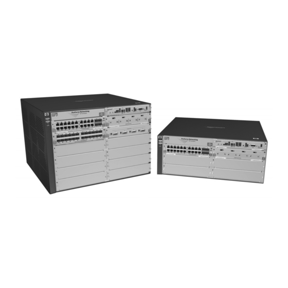
Introducing the HP ProCurve 5400zl Switches The HP ProCurve 5400zl Switches include the Switch 5406zl, 5412zl and their bundles, the Switch 5406zl-48G and Switch 5412zl-96G. They are multiport modular switches that provide Layer 3 routing features, and that feature low latency for high-speed networking. -
Page 12: Overview Of 5400Zl Switches
Overview of 5400zl Switches 5406zl Switches 5406zl Switch, 5406zl-48G Switch, and 5406zl-48G-PoE+ Switch. The HP ProcCurve 5406zl switch is available as an open 6-slot chassis (J8697A). The HP ProcCurve 5406zl-48G switch bundle (J8699A) ships with the 5406zl, 6-slot chassis and the following modules and power supply: •... -
Page 13: Hp Procurve 5406Zl Switch
Introducing the HP ProCurve 5400zl Switches Overview of 5400zl Switches HP ProCurve 5406zl Switch The HP ProcCurve 5406zl switch ships with the 5400zl Management Module and open, 6-slot chassis (J8697A). The switch needs at least one power supply to operate. -
Page 14: Hp Procurve 5406Zl-48G Switch
Introducing the HP ProCurve 5400zl Switches Overview of 5400zl Switches HP ProCurve 5406zl-48G Switch The HP ProcCurve 5406zl-48G switch bundle (J8699A) ships with the 5406zl, 6-slot chassis and the following modules and power supply: • Two 24-port 10/100/1000-T zl Modules (J8702A) •... -
Page 15: Hp Procurve 5412Zl Switch
Overview of 5400zl Switches HP ProCurve 5412zl Switch The HP ProcCurve 5412zl switch ships with the 5400zl Management Module and open, 12-slot chassis (J8698A). It does not ship with any power supplies. The switch needs at least one power supply to operate. -
Page 16: Hp Procurve 5412Zl-96G Switch
Introducing the HP ProCurve 5400zl Switches Overview of 5400zl Switches HP ProCurve 5412zl-96G Switch The HP ProcCurve 5412zl-96G switch bundle (J8700A) ships with the 5412zl, 12 slot chassis and the following modules and power supply: • Four 24-port 10/100/1000-T zl Modules (J8702A) •... -
Page 17: Network Connectivity, Speeds And Technologies
Introducing the HP ProCurve 5400zl Switches Network Connectivity, Speeds and Technologies Network Connectivity, Speeds and Technologies These products support optional network connectivity with the following speeds and technologies. Table 1-1. Optional Network Connectivity, Speeds and Technologies Transceiver Form-Factor and Connector... -
Page 18: Front Of The Switch
Introducing the HP ProCurve 5400zl Switches Front of the Switch Front of the Switch Status LEDs for the Fans, Power Supplies, and Switch Modules LED Mode Select button Auxiliary Port and indicator LEDs Power Locator LED and Fault LEDs Reset and Clear... -
Page 19: Leds
Introducing the HP ProCurve 5400zl Switches Front of the Switch LEDs As described in the next two tables, there are LEDs on the switch chassis and on the switch modules that keep you informed of the status of the switch and the network connections. - Page 20 Introducing the HP ProCurve 5400zl Switches Front of the Switch LEDs State Meaning Blinking If Flash, Fault, and Self Test LEDs are blinking, Compact Flash failed self-test. If Flash and Fault LEDs are blinking, an operational fault has occurred. If fast blinking (400ms On and 400ms Off), an operational alert occurred and is unresolved (for example, the Compact Flash is not present).
- Page 21 Introducing the HP ProCurve 5400zl Switches Front of the Switch LEDs State Meaning Modules (green - A module is installed in the switch module slot corresponding to the letter and the module letters is undergoing or has passed self test. This also occurs when you install a module when corresponding to the switch is already powered on (“hot swap”).
- Page 22 Introducing the HP ProCurve 5400zl Switches Front of the Switch Table 1-3. Switch Module LEDs These LEDs are located on the modules themselves, one pair for each port. State Meaning Link Indicates the port is enabled and receiving a link beat signal (for the twisted-pair ports), or a strong enough light level (for the fiber-optic ports) from the connected device.
-
Page 23: Led Mode Select Button And Indicator Leds
Introducing the HP ProCurve 5400zl Switches Front of the Switch LED Mode Select Button and Indicator LEDs To optimize the amount of information that can be displayed for each of the switch ports, the 5400zl switches use a Mode LED for each port. The operation... -
Page 24: Console Port
Introducing the HP ProCurve 5400zl Switches Front of the Switch • Slow Blinking = Internal PoE fault on this port. • Fast Blinking = This port is denied PoE power or has an external load fault. Mode LED: • On = PoE power is be supplied on this port •... - Page 25 Introducing the HP ProCurve 5400zl Switches Front of the Switch ■ Restoring Factory Default Configuration - When pressed with the Reset button in a specific pattern, the Clear button clears any configura- tion changes you may have made through the switch console, the web browser interface, or SNMP management, and restores the factory default configuration to the switch.
-
Page 26: Back Of The Switch
Introducing the HP ProCurve 5400zl Switches Back of the Switch Back of the Switch AC power connector Grounding lug mounting holes Slot for installing optional redundant power supply Power and Fault LEDs Figure 1-7. Back of a 5406zl Switch with One Power Supply... -
Page 27: Redundant Power Supply
Back of the Switch Redundant Power Supply Load-sharing redundant power supplies (HP ProCurve Switch zl 875 W Power Supply, J8712A, a Switch zl 1500 W Power Supply J8713A, or a Switch zl 1500 W PoE+ Power Supply J9306A) can be installed in the back of the 5400zl switches. -
Page 28: Switch Accessories
■ ONE Services zl Module (J9289A) N o t e For detailed information about the zl modules, refer to the HP ProCurve Switch zl Modules Installation Guide. For detailed information about PoE and PoE+ devices, refer to the HP ProCurve PoE (Power over Ethernet) Devices Planning and Implementation Guide. -
Page 29: Switch Features
ProCurve Manager—an SNMP-based graphical interface that is used to manage your entire network, included with your new switch • supported by ProCurve Network Manager—an HP OpenView appli- cation that accurately displays your switch on network maps and provides a graphical interface for configuring and monitoring your switch ■... - Page 30 Introducing the HP ProCurve 5400zl Switches Switch Features • IRDP - ICMP Router Discovery Protocol • OSPF- Open Shortest Path First • DHCP relay ■ support for many other advanced features to enhance network perfor- mance, security, and control— for a description, see the Management and Configuration Guide which is on the ProCurve Web site.
-
Page 31: Installing The 5400Zl Switches
5400zl switches. Included Parts The 5400zl switches have the following components shipped with them: ■ HP ProCurve 5400zl Switches Installation and Getting Started Guide, this manual or the 5400zl Quick Setup Sheet Customer Support/Warranty booklet ■... -
Page 32: Accessory Kits
8121-0967 A NEMA L6-20, 240V power cord is also available. Order part number 8121-0941. To order go to http://www.hp.com/buy/parts. J a p a n P o w e r C o r d W a r n i n g... -
Page 33: Installation Procedures
The modules are “hot swappable” though, so they can also be installed and removed after the switch is powered on. N o t e Make sure you use only HP ProCurve Switch zl Modules in your 5400zl switches. Install power supplies (page 2-10). - Page 34 Installing the 5400zl Switches Installation Procedures Connect the switch to a power source (page 2-19). Once the switch is mounted, plug it in to the nearby main power source. Connect a Power Supply Shelf (optional—page 2-19). You may wish to use a Power Supply Shelf with your switch. To do so you must connect the external power supply using the EPS cables supplied with the Power Supply Shelf.
-
Page 35: Installation Precautions
Installing the 5400zl Switches Installation Procedures Installation Precautions Follow these precautions when installing your 5400zl switch: W A R N I N G ■ Devices installed in a rack or cabinet should be mounted as low as possible, with the heaviest device at the bottom and progres- ... - Page 36 C a u t i o n s ■ If the switch is to be shipped in a rack, use only an HP 10000 series rack and a rail mounting kit (5070-0145) for each switch. Ensure the power source circuits are properly grounded, then use the ■...
-
Page 37: Prepare The Installation Site
C a u t i o n Make sure you install only HP ProCurve Switch zl Modules. Avoid any electrostatic discharge problems by handling the modules only by their bulkheads. - Page 38 Installing the 5400zl Switches Installation Procedures ■ Once the module is fully inserted, screw in the two retaining screws to secure the module in place. The screws should be tightened until they are secure, but not overtightened. If you do not use one or more of the slots, ensure the slot cover plate is ■...
- Page 39 Installing the 5400zl Switches Installation Procedures Use the extractor handles to seat the module completely. Then tighten the retaining screws on the module until they are secure, but do not overtighten them. Figure 2-1. Generic Chassis with Module Fully Installed...
-
Page 40: Optional) Install Another Power Supply
5 seconds and re-plug it for each power supply one at a time. Another load-sharing redundant power supply (either a HP ProCurve Switch zl 875 W Power Supply (J8712A), an HP ProCurve Switch zl 1500 W Power Supply (J8713A), or an HP ProCurve Switch1500 W PoE+ Power Supply (J9306A) can be installed in the back of the switch. - Page 41 Installing the 5400zl Switches Installation Procedures C a u t i o n The switch power supplies are hot swappable; they can be installed while the switch is receiving power from the supply in the other slot. But, as indicated by the caution statement on the power supply, the supply must not be connected to AC power before being installed or removed....
- Page 42 Installing the 5400zl Switches Installation Procedures tighten the four screws Figure 2-3. Back of Switch with Power Supply Fully Installed 2-12...
-
Page 43: Verify The Switch Passes Self Test
Installing the 5400zl Switches Installation Procedures 4. Verify the Switch Passes Self Test After you have installed any modules and the optional second power supply, but before mounting the switch in its network location, you should first verify it is working properly by plugging it into a power source and verifying it passes its self test. -
Page 44: Led Behavior
Installing the 5400zl Switches Installation Procedures If the LED display is different than what is described, especially if the Fault LED stays on for more than approximately 120 seconds or it starts blinking, the self test has not completed correctly. Refer to chapter 4, “Troubleshooting”... -
Page 45: Mount The Switch
Installing the 5400zl Switches Installation Procedures ■ The port LEDs on the switch modules go into their normal operational mode: If the ports are connected to active network devices, the Link LEDs • stay on and the Mode LEDs behave according to the mode selected. In the default mode (Activity), the Mode LEDs should flicker showing network activity on the port. - Page 46 Installing the 5400zl Switches Installation Procedures 8 mm M4 screws Figure 2-6. Attaching Brackets to the 5400zl Switch Partially install a screw into the top hole of a pair of holes that are 0.5 inches apart in each rack/cabinet upright as shown in the illustration below.
- Page 47 Installing the 5400zl Switches Installation Procedures Place the switch in the rack and lower it so the notches in the bottom of the bracket slide onto the screws, then tighten these screws. lower the switch with mounting brackets onto the partially installed screws, then tighten these screws Figure 2-8.
-
Page 48: Horizontal Surface Mounting
Installing the 5400zl Switches Installation Procedures Install the other screw into the upper hole in each bracket. Tighten these screws. install and tighten the other 12-24 screws Figure 2-9. Screws in Bracket Being Installed Horizontal Surface Mounting Place the switch on a table or other horizontal surface. Use a sturdy surface in an uncluttered area. -
Page 49: Connect The Switch To A Power Source
Installing the 5400zl Switches Installation Procedures Crimp the grounding lug to a properly grounded grounding wire. Re-attach the grounding lug to the switch with the two screws. Grounding lug screws Grounding lug Figure 2-10. Attaching Grounding Lug to the 5400zl Switch 7. -
Page 50: Eps Operation
Installing the 5400zl Switches Installation Procedures The HP ProCurve Switch zl Power Supply Shelf, (J8714A), hereafter referred to as the EPS, is an accessory product for the 5400zl switches. The EPS provides External Power-over-Ethernet (PoE) or PoE+ power for up to two 5400zl switch products. -
Page 51: Power Supply Shelf Leds
Installing the 5400zl Switches Installation Procedures Power Supply Shelf LEDs The EPS LEDs are duplicated on the front and back of the device. The following graphic shows an example of the front of the EPS. There are two dual colored (green/orange) LEDs for each EPS port: ■... -
Page 52: Connect The Network Devices
Installing the 5400zl Switches Installation Procedures To Power To Power Source Source 5406zl 5406zl EPS Cables Figure 2-12. Connecting the EPS to two 5406zl switches Although these examples show the EPS connecting to the 5406zl switch, it can also be connected to a 5412zl switch in the same manner. These examples also show the switch and the EPS using the J8713A power supply, the J8712A power supply can also be used. - Page 53 Installing the 5400zl Switches Installation Procedures Condition Diagnostic Tip Try the following procedures: Port LED is still off when • For the indicated port, verify both ends of the cabling, at the switch and the connected device, are a cable is securely connected.
-
Page 54: 10. (Optional) Connect A Console To The Switch
Installing the 5400zl Switches Installation Procedures 10. (Optional) Connect a Console to the Switch The 5400zl switches have a full-featured, easy to use console interface for performing the following tasks: Monitor switch and port status and observe network activity counters ■... -
Page 55: Direct Console Access
Installing the 5400zl Switches Installation Procedures Direct Console Access To connect a console to the switch, follow these steps: Connect the PC or terminal to the switch’s Console Port using the console cable included console port with the switch. (If your PC or terminal has a 25- pin serial connector, first attach a 9-pin to 25-pin... -
Page 56: Hot Swapping Switch Modules
Installing the 5400zl Switches Hot Swapping Switch Modules Hot Swapping Switch Modules The switch modules can be “hot swapped” (except for the Management Module, it is not hot swappable), that is installed or replaced while the switch is powered on (See Module Installation Notes on page 2-7). -
Page 57: Example Network Topologies
Installing the 5400zl Switches Example Network Topologies Example Network Topologies This section shows a few example network topologies in which the 5400zl switches can be implemented. Although these examples show the 6-slot chassis, the principles are the same for the 12-slot chassis. Basic Connectivity 5400zl Switch Phones, APs and other peripherals... -
Page 58: Use As An Edge Switch
5400zl switches can provide that access beyond the edge for a high number of network users. In the above illustration, two 5406zl switches are connected to an HP ProCurve Routing Switch 9308, which can serve as a campus backbone or core switch. -
Page 59: Optimizing The 10-Gbe Port Configuration
Example Network Topologies Optimizing the 10-GbE Port Configuration The 10-GbE ports on the HP ProCurve 8200zl switch are designed to deliver full 10 Gbps wire-speed to each port, where either one or two ports are in a linked state with another device. When three or four 10-GbE ports are in a linked state, when using an X2 (J8708A), CX4 (J8707A) or SFP+ (J9309A) module, the 10-GbE ports support an aggregate bandwidth of 28.8 Gbps across... - Page 60 Installing the 5400zl Switches Example Network Topologies Port A1 is guaranteed 10 Ports A2 and A3 share this channel Gbps because it does in a trunked link, which fairly in a trunked link, which fairly Port 4 is Port 4 is not need to share the balances the 14.4 Gbps balances the 14.4 Gbps...
-
Page 61: Getting Started With Switch Configuration
For more information on using the switch console and the other switch management interfaces: the web browser interface and the SNMP manage- ment tool, ProCurve Manager, please see the Management and Configuration Guide which is on the HP ProCurve Web site. See page 5-1 for details. -
Page 62: Using The Switch Setup Screen
(the default display). The CLI prompt appears displaying the switch model number, for example: ProCurve 5400zl# At the prompt, enter the setup command to display the Switch Setup screen. The following illustration is an example of a Setup screen with default settings. - Page 63 Getting Started With Switch Configuration Use the Tab key to select the Manager Password field and enter a manager password of up to 16 characters. Tab to the IP Config (DHCP/Bootp) field and use the Space bar to select the Manual option.
-
Page 64: Where To Go From Here
Getting Started With Switch Configuration Where to Go From Here The above procedure configures your switch with a Manager password, IP address, and subnet mask. As a result, with the proper network connections, you can now manage the switch from a PC equipped with Telnet, a web browser interface, or from an SNMP-based network management station using a tool such as ProCurve Manager. -
Page 65: Using The Ip Address For Remote Switch Management
Press a key, and you will then see the switch console command (CLI) prompt, for example (assuming there is no password): ProCurve 5400zl# Enter help or ? to see a list of commands that can be executed at the prompt. - Page 66 Getting Started With Switch Configuration Using the IP Address for Remote Switch Management ProCurve Switch 5406zl - Status: Information J8699A ProCurve Switch 5406zll PoE Status Figure 3-2. Switch Web Browser Interface - Status Overview For more information on using the web browser interface, please see the Management and Configuration Guide which is on the ProCurve Web site.
-
Page 67: Configuring The Procurve Wireless Edge Services Zl Modules
Getting Started With Switch Configuration Configuring the ProCurve Wireless Edge Services zl Modules (J9051A, J9052A) Configuring the ProCurve Wireless Edge Services zl Modules (J9051A, J9052A) Before beginning the configuration, backup the current configuration of the switch. The zl switch software must be updated to a version (K.12.40) that supports www.procurve.com/software the module. - Page 68 Getting Started With Switch Configuration Configuring the ProCurve Wireless Edge Services zl Modules (J9051A, J9052A) ■ To display the module’s IP address, enter: ProCurve (wireless-services-id)# show ip interfaces The following example enters the wireless-services context of a module installed in Slot B of a zl switch and then displays the IP address assigned by DHCP to the module: ProCurve# wireless-services b ProCurve(wireless-services-B)#show ip interface...
-
Page 69: Configuring Vlans On The Zl Switch
Getting Started With Switch Configuration Configuring the ProCurve Wireless Edge Services zl Modules (J9051A, J9052A) Configuring VLANs on the zl Switch In a wireless services-enabled zl switch, the Wireless Edge Services zl Module and the Redundant Wireless Services zl Module use ports on the switch to pass wired and wireless traffic to and from the network. -
Page 70: Configuring Wireless Lan Services
Getting Started With Switch Configuration Configuring the ProCurve Wireless Edge Services zl Modules (J9051A, J9052A) Configuring Wireless LAN Services To configure wireless LAN services on a wireless services-enabled zl switch, use one of the following management interfaces for the module: ■... -
Page 71: Replacing Components
C a u t i o n The HP ProCurve 5400zl Switch and its components are sensitive to static discharge. Use an antistatic wrist strap and observe all static precautions when hot swapping components. -
Page 72: Replacing Power Supplies
Replacing Power Supplies Replacing Power Supplies If your HP ProCurve 5400zl Switch is configured with redundant power supplies, you will not suffer any loss of traffic or performance if a power supply fails. Replace the failed component as soon as possible. One of the Internal Power LEDs on the management module will blink simultaneously with the switch Fault LED indicating which power supply failed. - Page 73 Figure 4-2. Power Supply Installation Tighten the four retaining screws that hold it in place. Be careful not to overtighten the screws. For more detail refer to the HP ProCurve Switch zl Internal Power Supply Installation Guide (5991-3787).
-
Page 74: Replacing Fan Trays
Replacing Components Replacing Fan Trays Replacing Fan Trays When a fan fails the Fan Status LED on the switch chassis will blink simultaneously with the switch Fault LED. In this case, the entire fan tray needs to be replaced. You cannot replace individual fans. The fan tray is hot swappable. -
Page 75: Replacing The Management Module
Replacing Components Replacing the Management Module Replacing the Management Module The switch does not have to be powered off to remove the management module, however when the management module is removed all ports will lose communication. ProCurve Networking recommends replacing the Manage- ment module, flash disk and battery (on the Management module) during scheduled down time. -
Page 76: Replacing The Management Module Compact Flash Card
Replacing Components Replacing the Management Module Compact Flash Card Replacing the Management Module Compact Flash Card The Compact Flash card is the primary non-volatile storage medium located on the management module that contains both the boot software and configuration files. When a Flash card fails the Flash status LED on the management module will blink simultaneously with the switch Fault LED. -
Page 77: Replacing The Management Module Battery
Replacing Components Replacing the Management Module Battery Replacing the Management Module Battery The battery on the management module is used to keep time for the internal switch clock. There is no indicator LED for when the battery dies. The only indication will be the internal clock will not keep the correct time. -
Page 78: Perchlorate Notice
Replacing Components Replacing the Management Module Battery Remove the old battery and dispose of properly. Insert the new battery with the lettering and the plus “+” sign facing up. Reinstall the management module into the switch. Use an equal amount of pressure and push both extractor handles closed to completely seat the module. -
Page 79: Replacing The J9289A One Services Zl Module Compact Flash Card
Replacing Components Replacing the J9289A ONE Services zl Module Compact Flash Card Replacing the J9289A ONE Services zl Module Compact Flash Card The Compact Flash card is the primary non-volatile storage medium located on the Services Module that contains both the boot software and configuration files. -
Page 80: Replacing The J9289A One Services Zl Module Disk Drive
Replacing Components Replacing the J9289A ONE Services zl Module Disk Drive Replacing the J9289A ONE Services zl Module Disk Drive The disk drive is the primary non-volatile storage medium located on the Services Module that contains both the boot software and configuration files. When a disk drive fails the “HDD status”... -
Page 81: Troubleshooting
ProCurve Web site at www.procurve.com/manuals. To display the list of down- loadable manuals, click on the following link: HP ProCurve 5400zl Switches. (You may want to bookmark this Web page for easy access in the future.) This chapter describes the following: ■... -
Page 82: Basic Troubleshooting Tips
Troubleshooting Basic Troubleshooting Tips Basic Troubleshooting Tips Most problems are caused by the following situations. Check for these items first when starting your troubleshooting: Faulty or loose cables. Look for loose or obviously faulty connections. ■ If they appear to be OK, make sure the connections are snug. If that does not correct the problem, try a different cable. - Page 83 See the Management and Configuration Guide which is on the HP ProCurve Web site. See page 5- for details.
-
Page 84: Diagnosing With The Leds
Troubleshooting Diagnosing with the LEDs Diagnosing with the LEDs Table 5-1 shows LED patterns on the switch and the switch modules that indicate problem conditions. Check in the table for the LED pattern you see on your switch Refer to the corresponding diagnostic tip on the next few pages. Table 5-1. -
Page 85: Diagnostic Tips
Troubleshooting Diagnosing with the LEDs Diagnostic Tips: Number Problem Solution ➊ The power supplies 1. Verify the power cord is plugged into an active power source and to the switch. installed in the Ensure these connections are snug. switch are not 2. - Page 86 Troubleshooting Diagnosing with the LEDs Number Problem Solution ➎ The module The modules are all tested whenever the switch is powered on, or reset (through installed in the slot the Reset button on the switch, or the Boot or Reset options in the console or web that corresponds to browser interface), and when they are hot swapped (installed when the switch is the letter that is...
- Page 87 Troubleshooting Diagnosing with the LEDs Number Problem Solution ➐ The network port During the module self test, described in tip number 4 earlier in this table, each for which the Link network port is also tested. If the port self test fails, the individual port is not usable, LED is blinking has but the rest of the ports on the module, which have passed their self test, will experienced a self...
- Page 88 • Verify you have used the correct cable type for the connection. – for any of the twisted-pair connections, in the default configuration (Auto), either a straight-through or a crossover cable can be used and the switch will automatically adjust its operation. See the “HP Auto-MDIX Feature” description on page B-6 for more information.
-
Page 89: Proactive Networking
Troubleshooting Proactive Networking Proactive Networking The 5400zl switches have built-in management capabilities that proactively help you manage your network including: finding and helping you fix the most common network error conditions ■ (for example, faulty network cabling, and non-standard network topologies) ■... -
Page 90: Hardware Diagnostic Tests
Troubleshooting Hardware Diagnostic Tests Hardware Diagnostic Tests Reasons for Resetting the Switch Generally, you only need to reset the switch when it needs to recognize a change in its hardware or software (console) configuration. Some circumstances in which you will need to reset the switch are: ■... -
Page 91: Testing The Switch By Resetting It
Troubleshooting Hardware Diagnostic Tests Testing the Switch by Resetting It If you believe the switch is not operating correctly, you can reset the switch to test its circuitry and operating code. To reset a switch, either: Unplug and plug in the power cord (power cycling) ■... -
Page 92: Testing Twisted-Pair Cabling
Troubleshooting Hardware Diagnostic Tests Testing Twisted-Pair Cabling If you think the cable should work but still isn’t working, it may not be compatible with the IEEE 802.3 Type 10Base-T, 100Base-TX, or 1000Base-T standards, as appropriate for the switch port type that the cable is connected to. -
Page 93: Restoring The Factory Default Configuration
Troubleshooting Restoring the Factory Default Configuration Restoring the Factory Default Configuration As part of your troubleshooting process, it may become necessary to return the switch configuration to the factory default settings. This process momen- tarily interrupts the switch operation, clears any passwords, clears the console event log, resets the network counters to zero, performs a complete self test, and reboots the switch into its factory default configuration including deleting an IP address, if one is configured. -
Page 94: Downloading New Code
The new code would be available on the ProCurve Networking Web site, www.procurve.com/software. HP Customer Support Services If you are still having trouble with your switch, Hewlett-Packard offers support 24 hours a day, seven days a week through the use of a number of automated electronic services. -
Page 95: Physical
• Switch 5412zl 15.86 kg (34.95 lbs) • Switch 5412zl-96G 26.31 kg (58.0 lbs) • Switch 5412zl-96G-PoE+ 26.15 kg (57.64 lbs) Electrical The HP ProCurve zl Power Supply Specfications:. J8712A J8713A AC voltage: 100-127 volts 200-240 volts 200-240 volts Maximum current:... -
Page 96: Environmental
Specifications Environmental Operating Non-Operating Temperature: 0C to 55C (32F to 131F) -40C to 70C (-40F to 158F) Relative humidity: 15% to 80% at 55C (131F) 15% to 90% at 65C (149F) (non-condensing) Maximum altitude: 3.1 km (10,000 ft) 4.6 km (15,000 ft) If you are installing either the J8705A, J8707A, or J9289A modules, or any of the X2 transceivers, the operating ambient temperature for the switch should not exceed 40C (104F). -
Page 97: Safety
Specifications Safety ■ EN60950 CSA 22.2 No. 60950 ■ ■ UL 60950 IEC 60950 ■ Technology Standards and Safety Compliance Technology Standards and Safety Compliance Laser safety information Technology Compatible EN/IEC SFP+ Media with these IEEE standard ("mini-GBIC") Lasers Lasers Converter standards compliance... - Page 98 Specifications Technology Standards and Safety Compliance (Continued) Laser safety information Technology Compatible EN/IEC SFP+ Media with these IEEE standard ("mini-GBIC") Lasers Lasers Converter standards compliance Lasers Lasers 1000-BX IEEE 802.3ah EN/IEC 60825 Class 1 Laser 1000BASE-BX10 Product Laser Klasse 1 10-Gig CX4 IEEE 802.3ak 10GBASE-CX4...
-
Page 99: Cabling And Technology Information
Cabling and Technology Information Cabling and Technology Information Specifications Cabling Specifications 10 Mbps Operation Category 3, 4 or 5, 100-ohm unshielded twisted-pair (UTP) or shielded twisted-pair (STP) cable, complying with IEEE 802.3 10BASE-T specifications. 100 Mbps Operation Category 5, 100-ohm UTP or STP cable, complying with IEEE Twisted-pair copper 802.3u 100BASE-TX specifications. -
Page 100: Technology Distance Specifications
Cabling and Technology Information Because of the increased speed provided by 1000BASE-T (Gigabit-T), network cable quality is more important than for either 10BASE-T or 100BASE-TX. Cabling plants being used to carry 1000BASE-T networking must comply with the IEEE 802.3ab standards. In particular, the cabling must pass tests for Attenuation, Near-End Crosstalk (NEXT), and Far-End Crosstalk (FEXT). - Page 101 Cabling and Technology Information Table 0-1. Technology Distance Specifications(Continued) Technology Supported cable type Multimode fiber Supported distances modal bandwidth 10-Gig SR multimode fiber 160 MHz*km 2 - 26 meters 200 MHz*km 2 - 33 meters 400 MHz*km 2 - 66 meters 500 MHz*km 2 - 82 meters 2000 MHz*km...
-
Page 102: Mode Conditioning Patch Cord
Cabling and Technology Information Mode Conditioning Patch Cord Mode Conditioning Patch Cord The following information applies to installations in which multimode fiber- optic cables are connected to a Gigabit-LX port or a 10-Gigabit LRM port. Multimode cable has a design characteristic called “Differential Mode Delay”, which requires the transmission signals be “conditioned”... - Page 103 Cabling and Technology Information Mode Conditioning Patch Cord If you connect the patch cord directly to the network cabling, you may need to install a female-to-female adapter to allow the cables to be connected together. Gigabit-LX port To network multimode Mode Conditioning cabling Patch Cord...
-
Page 104: Twisted-Pair Cable/Connector Pin-Outs
N o t e HP Auto-MDIX was developed and shared with the IEEE for the development of the IEEE 802.3ab standard. HP Auto-MDIX and the IEEE 802.3ab Auto MDI/ MDI-X feature are completely compatible. If you connect a Series 5400zl Switch twisted-pair port to another switch or hub, which typically have MDI-X ports, the Series 5400zl Switch port automat- ically operates as an MDI port. - Page 105 Cabling and Technology Information Twisted-Pair Cable/Connector Pin-Outs ■ For 10 Mbps connections to the ports, you can use Category 3, 4, or 5 100-ohm differential unshielded twisted-pair (UTP) or shielded twisted- pair (STP) cable, as supported by the IEEE 802.3 10Base-T standard. For 100 Mbps connections to the ports, use Category 5 100-ohm differen- ■...
-
Page 106: Straight-Through Twisted-Pair Cable For 10 Mbps Or 100 Mbps Network Connections
Straight-Through Twisted-Pair Cable for 10 Mbps or 100 Mbps Network Connections Because of the HP Auto-MDIX operation of the 10/100 ports on the switches, for all network connections, to PCs, servers or other end nodes, or to hubs or other switches, you can use straight-through cables. -
Page 107: Crossover Twisted-Pair Cable For 10 Mbps Or 100 Mbps Network Connection
Crossover Twisted-Pair Cable for 10 Mbps or 100 Mbps Network Connection The HP Auto-MDIX operation of the 10/100 ports on the switches also allows you to use crossover cables for all network connections, to PCs, servers or other end nodes, or to hubs or other switches. -
Page 108: Straight-Through Twisted-Pair Cable For 1000 Mbps Network Connections
Cabling and Technology Information Twisted-Pair Cable/Connector Pin-Outs Straight-Through Twisted-Pair Cable for 1000 Mbps Network Connections 1000Base-T connections require that all four pairs or wires be connected. Cable Diagram Figure B-4. Straight-through Cable Diagram for 1000 Mbps Network Connection N o t e Pins 1 and 2 on connector “A”... -
Page 109: C Safety And Regulatory Statements
Safety and Regulatory Statements Safety Information Documentation reference symbol. If the product is marked with this symbol, refer to the product documentation to get more information about the product. WARNING A WARNING in the manual denotes a hazard that can cause injury or death. -
Page 110: Informations Concernant La Sécurité
Safety and Regulatory Statements Informations concernant la sécurité Informations concernant la sécurité Symbole de référence à la documentation. Si le produit est marqué de ce symbole, reportez-vous à la documentation du produit afin d'obtenir des informations plus détaillées. WARNING Dans la documentation, un WARNING indique un danger susceptible d'entraîner des dommages corporels ou la mort. -
Page 111: Hinweise Zur Sicherheit
Safety and Regulatory Statements Hinweise zur Sicherheit Hinweise zur Sicherheit Symbol für Dokumentationsverweis. Wenn das Produkt mit diesem Symbol markiert ist, schlagen Sie bitte in der Produktdokumentation nach, um mehr Informationen über das Produkt zu erhalten. WARNING Symbol für Dokumentationsverweis. Wenn das Produkt mit diesem Symbol markiert ist, schlagen Sie bitte in der Produktdokumentation nach, um mehr Informationen über das Produkt zu erhalten. -
Page 112: Considerazioni Sulla Sicurezza
Safety and Regulatory Statements Considerazioni sulla sicurezza Considerazioni sulla sicurezza Simbolo di riferimento alla documentazione. Se il prodotto è contrassegnato da questo simbolo, fare riferimento alla documen- tazione sul prodotto per ulteriori informazioni su di esso. WARNING La dicitura WARNING denota un pericolo che può causare lesioni o morte. -
Page 113: Consideraciones Sobre Seguridad
Safety and Regulatory Statements Consideraciones sobre seguridad Consideraciones sobre seguridad Símbolo de referencia a la documentación. Si el producto va marcado con este símbolo, consultar la documentación del producto a fin de obtener mayor información sobre el producto. WARNING Una WARNING en la documentación señala un riesgo que podría resultar en lesiones o la muerte. -
Page 114: Safety Information (Japan
Safety and Regulatory Statements Safety Information (Japan) Safety Information (Japan) -
Page 115: Safety Information (China
Safety and Regulatory Statements Safety Information (China) Safety Information (China) -
Page 116: Emc Regulatory Statements
Safety and Regulatory Statements EMC Regulatory Statements EMC Regulatory Statements U.S.A. FCC Class A This equipment has been tested and found to comply with the limits for a Class A digital device, pursuant to Part 15 of the FCC Rules. These limits are designed to provide reasonable protection against interference when the equipment is operated in a commercial environment. -
Page 117: Korea
Safety and Regulatory Statements EMC Regulatory Statements Korea Taiwan Regulatory Model Identification Number For regulatory identification purposes, the ProCurve Series 5400zl Switches are assigned a Regulatory Model Number. The Regulatory Model Number for these switches is RSVLC- 0503. This regulatory number should not be confused with the marketing name (ProCurve Series 5400zl Switches), or product numbers (J8697A, J8698A, J8699A, and J8700A). -
Page 118: European Community
2) This product was tested with HP branded products only. his product was tested with HP branded products only. 2) This product was tested with HP branded products only. -
Page 119: China Regulatory
China Regulatory China Regulatory (Hg) (Cd) (Pb) (Cr(VI)) (PBB) (PCA) SJ/T11363-2006 SJ/T11363-2006 ProCurve Networking by HP This information is required by the People’s Republic of China as per their legislation titled “Management Methods for Controlling Pollution by Electronic Information Products”. C-11... - Page 120 Safety and Regulatory Statements China Regulatory C-12...
- Page 121 Recycle Statements Waste Electrical and Electronic Equipment (WEEE) Statements Disposal of Waste Equipment by Users in Private Household in the European Union This symbol on the product or on its packaging indicates that this product must not be disposed of with your other household waste.
- Page 122 Recycle Statements Waste Electrical and Electronic Equipment (WEEE) Statements Laitteiden hävittäminen kotitalouksissa Euroopan unionin alueella Jos tuotteessa tai sen pakkauksessa on tämä merkki, tuotetta ei saa hävittää kotitalousjätteiden mukana. Tällöin hävitettävä laite on toimitettava sähkölaitteiden ja elektronisten laitteiden kierrätyspisteeseen. Hävitettävien laitteiden erillinen käsittely ja kierrätys auttavat säästämään luonnonvaroja ja varmista- maan, että...
- Page 123 Recycle Statements Waste Electrical and Electronic Equipment (WEEE) Statements Smaltimento delle apparecchiature da parte di privati nel territorio dell'Unione Europea Questo simbolo presente sul prodotto o sulla sua confezione indica che il prodotto non può essere smaltito insieme ai rifiuti domestici. È responsabilità dell'utente smaltire le apparecchiature consegnan- dole presso un punto di raccolta designato al riciclo e allo smaltimento di apparecchiature elettriche ed elettroniche.
- Page 124 Para obter mais informações sobre locais que reciclam esse tipo de material, entre em contato com o escritório da HP em sua cidade, com o serviço de coleta de lixo ou com a loja em que o produto foi adquirido.
- Page 125 … B-6 Act LED … 1-11 crossover cable pin-out … B-9 auto MDI/MDI-X operation … B-8, B-10 HP Auto-MDIX feature … B-6 HP Auto-MDIX feature … B-6 MDI-X to MDI connections … B-8, B-10 auxiliary or USB port MDI-X to MDI-X connections …...
- Page 126 … 2-20 redundant power supply … 1-17, 2-11 operation … 2-20 resetting the switch for new module type … 2-26 EPS (PoE) power … 2-19 switch modules … 2-26 HP Auto-MDIX feature description … B-6 2 – Index...
- Page 127 Max … 1-11 Mode description … 1-12 network cables selecting the display … 1-13 HP Auto-MDIX feature … B-6 mode select indicators … 1-11 required types … 2-7 Module Status … 1-11 twisted-pair connector pin-outs … B-6 twisted-pair, wiring rules … B-6 network devices connecting to the switch …...
- Page 128 Mode … 1-12 replacing hardware ports disk drive … 4-10 console … 2-24 fans … 4-4 HP Auto-MDIX feature … B-6 flash memory card … 4-5, 4-6, 4-9 network connections … 2-23 Reset button power connector … 1-16 description … 1-14 Power LED location on switch …...
- Page 129 … 1-18 testing … 5-12 switch operation twisted-pair ports verifying after installation … 2-13 HP Auto-MDIX feature … B-6 Switch Setup screen … 3-2 configuring a subnet mask … 3-3 configuring an IP address … 3-3 field descriptions … 3-3...
- Page 130 VT-100 terminal serial cable connection for … 2-25 wireless edge services wireless modules … 3-7 wireless module backup process … 3-9 wiring rules for twisted-pair cables … B-6 6 – Index...
- Page 132 © Copyright 2005-2010 Hewlett-Packard Development Company, L.P. The information Copyright Hewlett-Packard Company, contained herein is subject to change without notice. The only warranties for HP products 2005 -2010. All rights reserved. and services are set forth in the express warranty statements accompanying such products and services.
Need help?
Do you have a question about the ProCurve 5400zl and is the answer not in the manual?
Questions and answers