HP 5400 zl Installation And Getting Started Manual
5400 zl series switches
Hide thumbs
Also See for HP 5400 zl:
- Reference manual (765 pages) ,
- Installation and getting started manual (134 pages) ,
- Quickspecs (101 pages)
Table of Contents
Advertisement
Advertisement
Table of Contents
Troubleshooting

Related Manuals for HP HP 5400 zl


Summary of Contents for HP HP 5400 zl
- Page 1 HP 5400 zl Switches Installation and Getting Started Guide Power over Ethernet...
- Page 3 HP 5400 zl Switches Installation and Getting Started Guide...
- Page 4 MERCHANTABILITY AND FITNESS FOR A PARTICULAR HP 5412-92G-PoE+/4G-SFP v2 zl Switch with Premium Software J9540A PURPOSE. Hewlett-Packard shall not be liable for errors contained herein or for incidental or consequential damages in HP 5412 zl Switch with Premium Software J9643A...
-
Page 5: Table Of Contents
Overview of HP 5400 zl Switches ........ - Page 6 1. Prepare the Installation Site ....... . 2-6 Cabling Infrastructure ........2-6 Installation Location .
- Page 7 Where to Go From Here ........3-4 Using the IP Address for Remote Switch Management .
- Page 8 Testing End-to-End Network Communications ....5-12 Restoring the Factory Default Configuration ..... . . 5-13 Downloading New Software .
- Page 9 C Safety and Regulatory Statements Safety Information ..........C-1 Informations concernant la sécurité...
-
Page 11: Introducing The Hp 5400 Zl Switches
Introducing the HP 5400 zl Switches The HP 5400 zl switches include the 5406 zl switch, 5412 zl switch and their bundles. They are multiport modular switches that provide Layer 3 routing features, and also feature low latency for high-speed networking. -
Page 12: Overview Of Hp 5400 Zl Switches
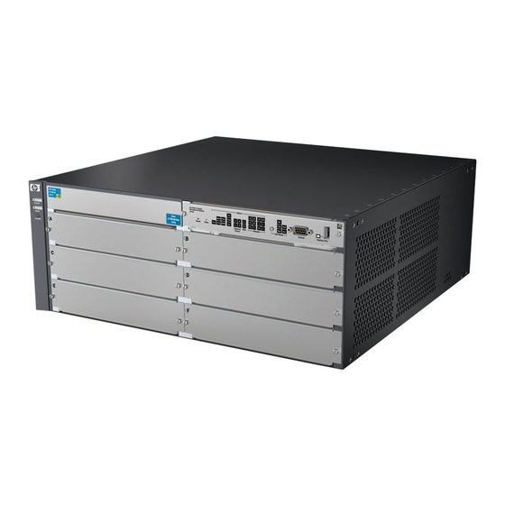
Introducing the HP 5400 zl Switches Overview of HP 5400 zl Switches Overview of HP 5400 zl Switches HP 5406 zl Switches The HP 5406 zl switch is available as an open 6-slot chassis (J9642A) with Premium Features activated. The HP 5406zl-48G switch bundle (J8699A) ships with the 5406 zl 6-slot chassis without Premium Features and the following: •... -
Page 13: Hp 5412 Zl Switches
One 20-port 10/100/1000 PoE+ / 4-port SFP v2 zl module (J9535A) • Two 1500W PoE+ Power Supplies (J9306A) • With Premium Features activated See “Switch Accessories” on page 1-16 for a list of the switch modules that can be installed in the HP 5400 zl switches. -
Page 14: Hp 5406 Zl Switch
Introducing the HP 5400 zl Switches Overview of HP 5400 zl Switches HP 5406 zl Switch The HP 5406 zl switch ships with the 5400 zl Management Module and open, 6-slot chassis (J9642A). The switch needs at least one power supply to operate. -
Page 15: Hp 5412 Zl Switch
Introducing the HP 5400 zl Switches Overview of HP 5400 zl Switches HP 5412 zl Switch The HP 5412 zl switch ships with the 5400 zl Management Module and open, 12-slot chassis (J9643A). It does not ship with any power supplies. The switch needs at least one power supply to operate. -
Page 16: Network Connectivity, Speeds And Technologies
Introducing the HP 5400 zl Switches Network Connectivity, Speeds and Technologies Network Connectivity, Speeds and Technologies These products support optional network connectivity as follows: Table 1-1. Optional Network Connectivity, Speeds and Technologies Transceiver Form-Factor and Connector Speed Technology Cabling SFP ("mini-GBIC") -
Page 17: Front Of The Switch
Switch Modules and slots with Link and Mode LEDs for each port located on each module Figure 1-3. Front of 5406zl-48G Switch This illustration shows the 5406zl-48G (J8699A), but the labeling and descrip- tions apply to all of the HP 5400 zl switches. -
Page 18: Leds
Introducing the HP 5400 zl Switches Front of the Switch LEDs As described in the next two tables, there are LEDs on the switch chassis and on the switch modules that keep you informed of the status of the switch and the network connections. - Page 19 Introducing the HP 5400 zl Switches Front of the Switch LEDs State Meaning Blinking If Flash, Fault, and Self Test LEDs are blinking, Compact Flash failed self-test. If Flash and Fault LEDs are blinking, an operational fault has occurred. If fast blinking (400ms On and 400ms Off), an operational alert occurred and is unresolved (for example, the Compact Flash is not present).
- Page 20 Introducing the HP 5400 zl Switches Front of the Switch LEDs State Meaning Modules (green - A module is installed in the switch module slot corresponding to the letter and the module letters is undergoing or has passed self test. This also occurs when you install a module when corresponding to the switch is already powered on (“hot swap”).
-
Page 21: Led Mode Select Button And Indicator Leds
Introducing the HP 5400 zl Switches Front of the Switch Table 1-3. Switch Module LEDs These LEDs are located on the modules themselves, one pair for each port. State Meaning Link Indicates the port is enabled and receiving a link beat signal (for the twisted-pair ports), or a strong enough light level (for the fiber-optic ports) from the connected device. - Page 22 Introducing the HP 5400 zl Switches Front of the Switch Mode LEDs LED Mode Select button (one for each port) and indicator LEDs Figure 1-4. Mode LEDs and LED Mode Select Button If the Activity indicator LED is lit, each port Mode LED displays ■...
-
Page 23: Console Port
Introducing the HP 5400 zl Switches Front of the Switch Console Port This port is used to connect a console to the switch by using the serial cable supplied with the switch. This connection is described under “Connecting a Console to the Switch” in chapter 2, “Installing the 5400 zl Switches”. The console is a full-featured interface that can be used to configure, monitor, and troubleshoot the switch. -
Page 24: Back Of The Switch
Introducing the HP 5400 zl Switches Back of the Switch Back of the Switch AC power connector Grounding lug mounting holes Slot for installing optional redundant power supply Power and Fault LEDs Figure 1-5. Back of a 5406 zl switch with one power supply... -
Page 25: Redundant Power Supply
Introducing the HP 5400 zl Switches Back of the Switch Redundant Power Supply Load-sharing redundant power supplies (HP Switch zl 875 W Power Supply, J8712A, a Switch zl 1500 W Power Supply J8713A, or a Switch zl 1500 W PoE+ Power Supply J9306A) can be installed in the back of the 5400 zl switches. -
Page 26: Switch Accessories
Introducing the HP 5400 zl Switches Switch Accessories Switch Accessories Accessories of the 5400 zl switches include a 6 or 12-slot chassis for installing any of the available zl Modules. The supported zl modules include: ■ 24-Port 10/100/1000 PoE+ zl Module (J9307A) ■... -
Page 27: Switch Features
Introducing the HP 5400 zl Switches Switch Features Switch Features The features of the 5400 zl switches include: N o t e Some of the listed 5400 zl switch features require a Premium License. ■ modules can be installed in any order and in any combination and can the “hot swapped”... - Page 28 Introducing the HP 5400 zl Switches Switch Features • supported by ProCurve Manager—an HP OpenView application that accurately displays your switch on network maps and provides a graphical interface for configuring and monitoring your switch support for the Spanning Tree Protocol to eliminate network loops ■...
-
Page 29: Installing The Hp 5400 Zl Switches
The 5400 zl switches have the following components shipped with them: ■ HP 5400 zl Switch Welcome Mat HP 5400 zl Switch Read Me First ■ HP 5400 zl Switches Safety and Regulatory Information ■ HP Switches General Safety and Regulatory Information ■ ■... -
Page 30: Accessory Kits
Installing the HP 5400 zl Switches Included Parts Accessory Kits 5406 zl Accessory Kit (5069-8561) 5412 zl Accessory Kit (5069-8562) two mounting brackets two mounting brackets - these brackets are twice as long as the brackets for the 5406 zl switches... -
Page 31: Installation Procedures
Installing the HP 5400 zl Switches Installation Procedures Installation Procedures Summary Follow these easy steps to install your switch. The rest of this chapter provides details on these steps. Prepare the installation site (page 2-6). Make sure the physical environment into which you will be installing the switch is properly prepared including having the correct network cabling ready to connect to the switch, and having a good location for the switch. -
Page 32: Installation Precautions
Installing the HP 5400 zl Switches Installation Procedures 8. Connect a Power Supply Shelf (optional—page 2-18). You may wish to use a Power Supply Shelf with your switch. To do so you must connect the external power supply using the EPS cables supplied with the Power Supply Shelf. -
Page 33: Installation Precautions (Continued)
Installing the HP 5400 zl Switches Installation Procedures Installation Precautions (continued) C a u t i o n s If the switch is to be shipped in a rack, use only an HP 10000 series rack ■ and a rail mounting kit (5070-0145) for each switch. -
Page 34: Prepare The Installation Site
Installing the HP 5400 zl Switches Installation Procedures 1. Prepare the Installation Site Cabling Infrastructure Ensure the cabling infrastructure meets the necessary network specifications. See Appendix B, “Cabling and Technology Information” on page B-1 for more information. Installation Location Before installing the switch, plan its location and orientation relative to other devices and equipment: In the front of the switch, allow at least 7.6 cm (3 inches) of space for the... - Page 35 Installing the HP 5400 zl Switches Installation Procedures ■ Once the module is fully inserted, screw in the two retaining screws to secure the module in place. The screws should be tightened until they are secure, but not overtightened. If you do not use one or more of the slots, ensure the slot cover plate is ■...
-
Page 36: Installing A Management Module Battery
Installing the HP 5400 zl Switches Installation Procedures Use the extractor handles to seat the module completely. Then tighten the retaining screws on the module until they are secure, but do not overtighten them. Figure 2-1. Generic chassis with module fully installed... - Page 37 Installing the HP 5400 zl Switches Installation Procedures Installing a New Battery. Figure 2-2. Battery location on Management Module Insert the new battery with the lettering and the plus “+” sign facing up. Install the management module into the switch.
-
Page 38: Optional) Install Another Power Supply
Installing the HP 5400 zl Switches Installation Procedures 3. (Optional) Install Another Power Supply C a u t i o n The 5400 zl switches are designed to provide continuously operating PoE or PoE+ power in the event of a single power supply failure with only a loss of PoE or PoE+ power to lower priority ports. - Page 39 Installing the HP 5400 zl Switches Installation Procedures C a u t i o n The switch power supplies are hot swappable; they can be installed while the switch is receiving power from the supply in the other slot. But, as indicated by the caution statement on the power supply, the supply must not be connected to AC power before being installed or removed.
-
Page 40: Verify The Switch Passes Self Test
Installing the HP 5400 zl Switches Installation Procedures tighten the four screws Figure 2-4. Back of switch with power supply fully installed 4. Verify the Switch Passes Self Test After you have installed any modules and the optional second power supply,... - Page 41 Installing the HP 5400 zl Switches Installation Procedures N o t e The 5400 zl switches do not have a power switch. They are powered on when the power cord is connected to the switch and to a power source.
-
Page 42: Led Behavior
Installing the HP 5400 zl Switches Installation Procedures LED Behavior: During the self test: Initially, Power, Fault, Locator, and all the switch chassis LEDs are on. Then, ■ after approximately 30 seconds, all the module LEDs go on as the modules... - Page 43 Installing the HP 5400 zl Switches Installation Procedures E q u i p m e n t If you are installing the switch in an equipment cabinet, in place of the C a b i n e t 12-24 screws supplied with the switch, use the clips and screws that came with N o t e the cabinet.
- Page 44 Installing the HP 5400 zl Switches Installation Procedures Partially install a screw into the top hole of a pair of holes that are 0.5 inches apart in each rack/cabinet upright as shown in the illustration below. Ensure that the screws are at the same level in each upright.
-
Page 45: Horizontal Surface Mounting
Installing the HP 5400 zl Switches Installation Procedures Install the other screw into the upper hole in each bracket. Tighten these screws. install and tighten the other 12-24 screws Figure 2-10. Screws in bracket being installed Horizontal Surface Mounting Place the switch on a table or other horizontal surface. Use a sturdy surface in an uncluttered area. -
Page 46: Connect The Switch To A Power Source
Installing the HP 5400 zl Switches Installation Procedures Crimp the grounding lug to a properly grounded grounding wire. Re-attach the grounding lug to the switch with the two screws. Grounding lug screws Grounding lug Figure 2-11. Attaching grounding lug to the 5400 zl switch 7. -
Page 47: Eps Operation
Installing the HP 5400 zl Switches Installation Procedures The HP Switch zl Power Supply Shelf, (J8714A), hereafter referred to as the EPS, is an accessory product for the 5400 zl switches. The EPS provides External Power-over-Ethernet (PoE) or PoE+ power for up to two 5400 zl switch products. -
Page 48: Power Supply Shelf Leds
Installing the HP 5400 zl Switches Installation Procedures Power Supply Shelf LEDs The EPS LEDs are duplicated on the front and back of the device. The following graphic shows an example of the front of the EPS. There are two... -
Page 49: Connect The Network Devices
Installing the HP 5400 zl Switches Installation Procedures To Power To Power Source Source 5406 zl 5406 zl EPS Cables Figure 2-14. Connecting the EPS to two 5406 zl switches Although these examples show the EPS connecting to the 5406 zl switch, it can also be connected to a 5412 zl switch in the same manner. -
Page 50: 10. (Optional) Connect A Console To The Switch
Installing the HP 5400 zl Switches Installation Procedures Condition Diagnostic Tip Try the following procedures: Port LED is still off when • For the indicated port, verify both ends of the cabling, at the switch and the connected device, are a cable is securely connected. -
Page 51: Terminal Configuration
Installing the HP 5400 zl Switches Installation Procedures The console can be accessed through these methods: ■ Out-of-band: Connect a PC or VT-100 terminal, to be used as a console, directly to the switch using the serial cable that comes with the 5400 zl switches. -
Page 52: Direct Console Access
Installing the HP 5400 zl Switches Installation Procedures Direct Console Access To connect a console to the switch, follow these steps: Connect the PC or terminal to the switch’s Console Port using the console cable included console port with the switch. (If your... -
Page 53: Telnet Console Access
Installing the HP 5400 zl Switches Installation Procedures Figure 2-16. RJ-45 to DB-9 pinouts Table 2-2. Mapping of RJ-45 to DB-9 RJ-45 (Signal reference from DB-9 (Signal reference from PC) Chassis) Reserved Reserved Reserved Reserved Reserved Telnet Console Access To access the switch through a telnet session, follow these steps:... -
Page 54: Hot Swapping Switch Modules
Installing the HP 5400 zl Switches Hot Swapping Switch Modules Hot Swapping Switch Modules The switch modules can be “hot swapped” (except for the Management Module, it is not hot swappable), that is installed or replaced while the switch is powered on (See Module Installation Notes on page 2-6). -
Page 55: Example Network Topologies
Installing the HP 5400 zl Switches Example Network Topologies Example Network Topologies This section shows a few example network topologies in which the 5400 zl switches can be implemented. Although these examples show the 6-slot chassis, the principles are the same for the 12-slot chassis. -
Page 56: Use As An Edge Switch
Installing the HP 5400 zl Switches Example Network Topologies Use as an Edge Switch Trunked Routing Switch 9308 redundant Gigabit fiber-optic cables 5406 zl 5406 zl Switch Switch Figure 2-18. Edge switch configuration When your network expands and the users need to access resources beyond the edge of the local network, the 5400 zl switches are excellent platforms for that expansion. -
Page 57: Optimizing The 10-Gbe Port Configuration
Example Network Topologies Optimizing the 10-GbE Port Configuration The 10-GbE ports on the HP 5400 zl switch are designed to deliver full 10 Gbps wire-speed to each port, where either one or two ports are in a linked state with another device. When three or four 10-GbE ports are in a linked state, when using an X2 (J8708A), CX4 (J8707A) or SFP+ (J9309A) module, the 10- GbE ports support an aggregate bandwidth of 28.8 Gbps across the linked... -
Page 58: Optimizing The 10-Gbe Port Configuration With Version 2 Zl Modules
Installing the HP 5400 zl Switches Example Network Topologies Figure 2-20. Guaranteeing 10 Gbps on a specific port. Optimizing the 10-GbE Port Configuration with version 2 zl modules The 10-GbE Module (J9538A) is designed to deliver additional performance for zl switches. The 5400 zl has a fabric design that allows for optimal performance with 10GbE v2 zl modules. - Page 59 Installing the HP 5400 zl Switches Example Network Topologies Ports A6 and A8 Ports A5 and A7 are not used are not used Figure 2-21. Version 2 optimized 10-GbE port configuration The 5400 zl can send 32 Gbps per module with 64 byte packets. This allows for an oversubscription for the HP 8-port 10-GbE SFP+ v2 zl Module (J9538A) on the 5400 zl, or 2 wire rate 10GbE ports.
-
Page 61: Getting Started With Switch Configuration
Getting Started With Switch Configuration This chapter is a guide for using the console Switch Setup screen to quickly assign an IP (Internet Protocol) address and subnet mask to the switch, set a Manager password, and, optionally, configure other basic features. For more information on using the switch console and the other switch management interfaces: the web browser interface and the SNMP manage- ment tool, ProCurve Manager, please see the Management and Configuration... -
Page 62: Using The Switch Setup Screen
Getting Started With Switch Configuration N o t e By default, the switch is configured to acquire an IP address configuration from a DHCP or Bootp server. To use DHCP/Bootp instead of the manual method described in this chapter, see “DHCP/Bootp Operation” in the Management and Configuration Guide which is on the HP networking Web site. - Page 63 Getting Started With Switch Configuration Use the Tab key to select the Manager Password field and enter a manager password of up to 16 characters. Tab to the IP Config (DHCP/Bootp) field and use the Space bar to select the Manual option.
-
Page 64: Where To Go From Here
Getting Started With Switch Configuration Where to Go From Here The above procedure configures your switch with a Manager password, IP address, and subnet mask. As a result, with the proper network connections, you can now manage the switch from a PC equipped with Telnet, a web browser interface, or from an SNMP-based network management station using a tool such as ProCurve Manager. -
Page 65: Using The Ip Address For Remote Switch Management
Getting Started With Switch Configuration Using the IP Address for Remote Switch Management Using the IP Address for Remote Switch Management With your 5400 zl switches, you can use the switch’s IP address to manage the switch from any PC that is on the same subnet as the switch. You can use either a Telnet session or a standard web browser to manage the switch. - Page 66 Getting Started With Switch Configuration Using the IP Address for Remote Switch Management ProCurve Switch 5406zl - Status: Information J8699A ProCurve Switch 5406zll PoE Status Figure 3-2. Switch Web Browser Interface - Status Overview For more information on using the web browser interface, please see the Management and Configuration Guide which is on the HP networking Web site.
-
Page 67: Configuring The Hp Wireless Edge Services Zl Modules (J9051A, J9052A)
Getting Started With Switch Configuration Configuring the HP Wireless Edge Services zl Modules (J9051A, J9052A) Configuring the HP Wireless Edge Services zl Modules (J9051A, J9052A) Before beginning the configuration, backup the current configuration of the switch. The zl switch software must be updated to a version (K.12.40) that supports www.hp.com/networking/support the module. - Page 68 Getting Started With Switch Configuration Configuring the HP Wireless Edge Services zl Modules (J9051A, J9052A) ■ To display the module’s IP address, enter: HP(wireless-services-id)# show ip interfaces The following example enters the wireless-services context of a module installed in Slot B of a zl switch and then displays the IP address assigned by DHCP to the module: HP# wireless-services b HP(wireless-services-B)#show ip interface...
-
Page 69: Configuring Vlans On The Zl Switch
Getting Started With Switch Configuration Configuring the HP Wireless Edge Services zl Modules (J9051A, J9052A) Configuring VLANs on the zl Switch In a wireless services-enabled zl switch, the Wireless Edge Services zl Module and the Redundant Wireless Services zl Module use ports on the switch to pass wired and wireless traffic to and from the network. -
Page 70: Configuring Wireless Lan Services
Getting Started With Switch Configuration Configuring the HP Wireless Edge Services zl Modules (J9051A, J9052A) Configuring Wireless LAN Services To configure wireless LAN services on a wireless services-enabled zl switch, use one of the following management interfaces for the module: ■... -
Page 71: Replacing Components
For a complete list of parts and part numbers, see page 2-1. H o t S w a p p i n g The HP 5400 zl Switch supports “hot swapping” - the ability to replace the following hardware components while the switch is operating: a fan tray, power supply (if a second power supply is installed), interface module. -
Page 72: Replacing Power Supplies
Replacing Components Replacing Power Supplies Replacing Power Supplies If your HP E5400 zl Switch is configured with redundant power supplies, you will not suffer any loss of traffic or performance if a power supply fails. Replace the failed component as soon as possible. One of the Internal Power LEDs on the management module will blink simultaneously with the switch Fault LED indicating which power supply failed. - Page 73 Replacing Components Replacing Power Supplies Insert the power supply into the opening. Slide it all the way in until it connects to the switch. The power supply face plate will be flush with the back face of the switch. tighten the four screws Figure 4-2.
-
Page 74: Replacing Fan Trays
Replacing Components Replacing Fan Trays Replacing Fan Trays When a fan fails the Fan Status LED on the switch chassis will blink simultaneously with the switch Fault LED. In this case, the entire fan tray needs to be replaced. You cannot replace individual fans. The fan tray is hot swappable. -
Page 75: Replacing The Management Module
Replacing Components Replacing the Management Module Replacing the Management Module The switch does not have to be powered off to remove the management module, however when the management module is removed all ports will lose communication. HP networking recommends replacing all components during scheduled down time. -
Page 76: Replacing The Management Module Compact Flash Card
Replacing Components Replacing the Management Module Compact Flash Card Replacing the Management Module Compact Flash Card The Compact Flash card is the primary non-volatile storage medium located on the management module that contains both the boot software and configuration files. When a Flash card fails the CF status LED on the management module will blink simultaneously with the switch Fault LED. -
Page 77: Replacing The J9289A One Services Zl Module Compact Flash Card
Replacing Components Replacing the J9289A ONE Services zl Module Compact Flash Card Replacing the J9289A ONE Services zl Module Compact Flash Card The Compact Flash card is the primary non-volatile storage medium located on the Services Module that contains both the boot software and configuration files. -
Page 78: Replacing The J9289A One Services Zl Module Disk Drive
Replacing Components Replacing the J9289A ONE Services zl Module Disk Drive Replacing the J9289A ONE Services zl Module Disk Drive The disk drive is the primary non-volatile storage medium located on the Services Module that contains both the boot software and configuration files. When a disk drive fails the “HDD status”... -
Page 79: Troubleshooting
Troubleshooting This chapter describes how to troubleshoot your 5400 zl switches. Note that this document describes troubleshooting mostly from a hardware perspective. You can perform more in-depth troubleshooting using the software tools available with the switch, including the full-featured console interface, the built-in web browser interface, and ProCurve Manager, the SNMP-based network management tool. -
Page 80: Basic Troubleshooting Tips
Troubleshooting Basic Troubleshooting Tips Basic Troubleshooting Tips Most problems are caused by the following situations. Check for these items first when starting your troubleshooting: Faulty or loose cables. Look for loose or obviously faulty connections. ■ If they appear to be OK, make sure the connections are snug. If that does not correct the problem, try a different cable. - Page 81 Troubleshooting Basic Troubleshooting Tips ■ Connecting to devices that have a fixed full-duplex configuration. The RJ-45 ports on the 5400 zl switches are all configured as “Auto”. That is, when connecting to attached devices, the switch will operate in one of two ways to determine the link speed and the communication mode (half duplex or full duplex): •...
-
Page 82: Diagnosing With The Leds
Troubleshooting Diagnosing with the LEDs Diagnosing with the LEDs Table 5-1 shows LED patterns on the switch and the switch modules that indicate problem conditions. Check in the table for the LED pattern you see on your switch Refer to the corresponding diagnostic tip on the next few pages. Table 5-1. -
Page 83: Diagnostic Tips
Troubleshooting Diagnosing with the LEDs Diagnostic Tips: Number Problem Solution ➊ The power supplies 1. Verify the power cord is plugged into an active power source and to the switch. installed in the Ensure these connections are snug. switch are not 2. - Page 84 Troubleshooting Diagnosing with the LEDs Number Problem Solution ➎ The module The modules are all tested whenever the switch is powered on, or reset (through installed in the slot the Reset button on the switch, or the Boot or Reset options in the console or web that corresponds to browser interface), and when they are hot swapped (installed when the switch is the letter that is...
- Page 85 Troubleshooting Diagnosing with the LEDs Number Problem Solution ➐ The network port During the module self test, described in tip number 4 earlier in this table, each for which the Link network port is also tested. If the port self test fails, the individual port is not usable, LED is blinking has but the rest of the ports on the module, which have passed their self test, will experienced a self...
- Page 86 Troubleshooting Diagnosing with the LEDs Number Problem Solution The network Try the following procedures: connection is not • For the indicated port, verify both ends of the cabling, at the switch and the working properly. connected device, are securely connected. •...
-
Page 87: Hp Networking Tools
Troubleshooting HP networking tools HP networking tools The 5400 zl switches have built-in management capabilities that proactively help you manage your network including: finding and helping you fix the most common network error conditions ■ (for example, faulty network cabling, and non-standard network topologies) ■... -
Page 88: Hardware Diagnostic Tests
Troubleshooting Hardware Diagnostic Tests Hardware Diagnostic Tests Reasons for Resetting the Switch Generally, you only need to reset the switch when it needs to recognize a change in its hardware or software (console) configuration. Some circumstances in which you will need to reset the switch are: ■... -
Page 89: Testing The Switch By Resetting It
Troubleshooting Hardware Diagnostic Tests Testing the Switch by Resetting It If you believe the switch is not operating correctly, you can reset the switch to test its circuitry and operating code. To reset a switch, either: ■ Unplug and plug in the power cord (power cycling) ■... -
Page 90: Testing Twisted-Pair Cabling
Troubleshooting Hardware Diagnostic Tests Testing Twisted-Pair Cabling If you think the cable should work but still isn’t working, it may not be compatible with the IEEE 802.3 Type 10Base-T, 100Base-TX, or 1000Base-T standards, as appropriate for the switch port type that the cable is connected to. -
Page 91: Restoring The Factory Default Configuration
Troubleshooting Restoring the Factory Default Configuration Restoring the Factory Default Configuration As part of your troubleshooting process, it may become necessary to return the switch configuration to the factory default settings. This process momen- tarily interrupts the switch operation, clears any passwords, clears the console event log, resets the network counters to zero, performs a complete self test, and reboots the switch into its factory default configuration including deleting an IP address, if one is configured. -
Page 92: Downloading New Software
HP Customer Support Services If you are still having trouble with your switch, Hewlett-Packard offers support 24 hours a day, seven days a week through the use of a number of automated electronic services. See the Customer Support/Warranty booklet that came with your switch for information on how to use these services to get technical www.hp.com/networking/support... - Page 93 Troubleshooting HP Customer Support Services 5-15...
- Page 94 Troubleshooting HP Customer Support Services 5-16...
-
Page 95: Physical
Specifications Physical Width: 44.2 cm (17.4 in) Depth: 45.0 cm (17.7 in) Height: • 5406 zl Switch 17.5 cm (6.8 in) • 5412 zl Switch 30.74 cm (12.1 in) Weight: • 5406 zl Switch base system(J8697A) 10.68 kg (23.55 lbs) •... -
Page 96: Environmental
Specifications Environmental Operating Non-Operating Temperature: 0C to 55C (32F to 131F) -40C to 70C (-40F to 158F) Relative humidity: 15% to 80% at 55C (131F) 15% to 90% at 65C (149F) (non-condensing) Maximum altitude: 3.1 km (10,000 ft) 4.6 km (15,000 ft) If you are installing either the J8705A, J8707A, or J9289A modules, or any of the X2 transceivers, the operating ambient temperature for the switch should not exceed 40C (104F). -
Page 97: Safety
Specifications Safety ■ EN60950 CSA 22.2 No. 60950 ■ ■ UL 60950 IEC 60950 ■ Technology Standards and Safety Compliance Table A-1. Technology Standards and Safety Compliance Laser safety information Technology Compatible EN/IEC SFP+ Media with these IEEE standard ("mini-GBIC") Lasers Lasers Converter... - Page 98 Specifications Table A-1. Technology Standards and Safety Compliance (Continued) Laser safety information Technology Compatible EN/IEC SFP+ Media with these IEEE standard ("mini-GBIC") Lasers Lasers Converter standards compliance Lasers Lasers 1000-BX IEEE 802.3ah EN/IEC 60825 Class 1 Laser 1000BASE-BX10 Product Laser Klasse 1 10-Gig CX4 IEEE 802.3ak 10GBASE-CX4...
-
Page 99: B Cabling And Technology Information
Cabling and Technology Information Cabling and Technology Information Specifications Table B-1. Cabling Specifications 10 Mbps Operation Category 3, 4 or 5, 100-ohm unshielded twisted-pair (UTP) or shielded twisted-pair (STP) cable, complying with IEEE 802.3 10BASE-T specifications. 100 Mbps Operation Category 5, 100-ohm UTP or STP cable, complying with IEEE 802.3u 100BASE-TX specifications. - Page 100 Cabling and Technology Information Note on 1000BASE-T Cable Requirements. The Category 5 networking cables that work for 100BASE-TX connections should also work for 1000BASE-T, as long as all four-pairs are connected. But, for the most robust connections, you should use cabling that complies with the Category 5e specifications, as described in Addendum 5 to the TIA-568-A standard (ANSI/ TIA/EIA-568-A-5).
-
Page 101: Technology Distance Specifications
Cabling and Technology Information Technology Distance Specifications Table B-2. Technology Supported cable type Multimode fiber Supported distances modal bandwidth 100-FX multimode fiber up to 2,000 meters 100-BX single mode fiber 0.5 - 10,000 meters 1000-T twisted-pair copper up to 100 meters 10GBASE-T twisted-pair copper Cat 6 unshielded - up to 55 meters... - Page 102 Cabling and Technology Information Table B-2. Technology Supported cable type Multimode fiber Supported distances modal bandwidth 10-Gig ER single mode fiber 2 - 40,000 meters CX4 Media Converter 12-strand female-female multi- 150 MHz*km 1 - 50 meters mode fiber MPO ribbon cable 500 MHz*km 1 - 100 meters with MTP connectors, in a...
-
Page 103: Mode Conditioning Patch Cord
Cabling and Technology Information Mode Conditioning Patch Cord Mode Conditioning Patch Cord The following information applies to installations in which multimode fiber- optic cables are connected to a Gigabit-LX port or a 10-Gigabit LRM port. Multimode cable has a design characteristic called “Differential Mode Delay”, which requires the transmission signals be “conditioned”... - Page 104 Cabling and Technology Information Mode Conditioning Patch Cord Gigabit-LX port To network multimode Mode Conditioning cabling Patch Cord Single mode section plugs into Tx The multimode cable in the patch cord port on Gigabit-LX Transceiver or must match the characteristics of your Gigabit-LX transceiver network cable Figure B-1.
-
Page 105: Twisted-Pair Cable/Connector Pin-Outs
Cabling and Technology Information Twisted-Pair Cable/Connector Pin-Outs Twisted-Pair Cable/Connector Pin-Outs The HP Auto-MDIX Feature. In the default configuration, “Auto”, the 10/100Base-TX ports on the 10/100-TX and PoE Modules used in the 5400 zl Switches all automatically detect the type of port on the connected device and operate as either an MDI or MDI-X port, whichever is appropriate. - Page 106 Cabling and Technology Information Twisted-Pair Cable/Connector Pin-Outs ■ For 10 Mbps connections to the ports, you can use Category 3, 4, or 5 100-ohm differential unshielded twisted-pair (UTP) or shielded twisted- pair (STP) cable, as supported by the IEEE 802.3 10Base-T standard. For 100 Mbps connections to the ports, use Category 5 100-ohm differen- ■...
-
Page 107: Straight-Through Twisted-Pair Cable For 10 Mbps Or 100 Mbps Network Connections
Cabling and Technology Information Twisted-Pair Cable/Connector Pin-Outs Straight-Through Twisted-Pair Cable for 10 Mbps or 100 Mbps Network Connections Because of the HP Auto-MDIX operation of the 10/100 ports on the switches, for all network connections, to PCs, servers or other end nodes, or to hubs or other switches, you can use straight-through cables. -
Page 108: Crossover Twisted-Pair Cable For 10 Mbps Or 100 Mbps Network Connection
Cabling and Technology Information Twisted-Pair Cable/Connector Pin-Outs Crossover Twisted-Pair Cable for 10 Mbps or 100 Mbps Network Connection The HP Auto-MDIX operation of the 10/100 ports on the switches also allows you to use crossover cables for all network connections, to PCs, servers or other end nodes, or to hubs or other switches. -
Page 109: Straight-Through Twisted-Pair Cable For 1000 Mbps Network Connections
Cabling and Technology Information Twisted-Pair Cable/Connector Pin-Outs Straight-Through Twisted-Pair Cable for 1000 Mbps Network Connections 1000Base-T connections require that all four pairs or wires be connected. Cable Diagram Figure B-4. Straight-through Cable Diagram for 1000 Mbps Network Connection N o t e Pins 1 and 2 on connector “A”... - Page 111 Cabling and Technology Information Twisted-Pair Cable/Connector Pin-Outs B-13...
-
Page 112: C Safety And Regulatory Statements
Safety and Regulatory Statements Safety Information Documentation reference symbol. If the product is marked with this symbol, refer to the product documentation to get more information about the product. WARNING A WARNING in the manual denotes a hazard that can cause injury or death. -
Page 113: Informations Concernant La Sécurité
Safety and Regulatory Statements Informations concernant la sécurité Informations concernant la sécurité Symbole de référence à la documentation. Si le produit est marqué de ce symbole, reportez-vous à la documentation du produit afin d'obtenir des informations plus détaillées. WARNING Dans la documentation, un WARNING indique un danger susceptible d'entraîner des dommages corporels ou la mort. -
Page 114: Hinweise Zur Sicherheit
Safety and Regulatory Statements Hinweise zur Sicherheit Hinweise zur Sicherheit Symbol für Dokumentationsverweis. Wenn das Produkt mit diesem Symbol markiert ist, schlagen Sie bitte in der Produktdokumentation nach, um mehr Informationen über das Produkt zu erhalten. WARNING Symbol für Dokumentationsverweis. Wenn das Produkt mit diesem Symbol markiert ist, schlagen Sie bitte in der Produktdokumentation nach, um mehr Informationen über das Produkt zu erhalten. -
Page 115: Considerazioni Sulla Sicurezza
Safety and Regulatory Statements Considerazioni sulla sicurezza Considerazioni sulla sicurezza Simbolo di riferimento alla documentazione. Se il prodotto è contrassegnato da questo simbolo, fare riferimento alla documen- tazione sul prodotto per ulteriori informazioni su di esso. WARNING La dicitura WARNING denota un pericolo che può causare lesioni o morte. -
Page 116: Consideraciones Sobre Seguridad
Safety and Regulatory Statements Consideraciones sobre seguridad Consideraciones sobre seguridad Símbolo de referencia a la documentación. Si el producto va marcado con este símbolo, consultar la documentación del producto a fin de obtener mayor información sobre el producto. WARNING Una WARNING en la documentación señala un riesgo que podría resultar en lesiones o la muerte. -
Page 117: Informações De Segurança
Safety and Regulatory Statements Informações de Segurança Informações de Segurança Símbolo de referência à documentação. Se o produto estiver marcado com este símbolo, consulte a documentação do produto para obter mais informações sobre ele. AVISO Um AVISO no manual indica um perigo que possa causar ferimentos ou morte. -
Page 118: Safety Information (Japan
Safety and Regulatory Statements Safety Information (Japan) Safety Information (Japan) -
Page 119: Safety Information (China
Safety and Regulatory Statements Safety Information (China) Safety Information (China) -
Page 120: Emc Regulatory Statements
Safety and Regulatory Statements EMC Regulatory Statements EMC Regulatory Statements U.S.A. FCC Class A This equipment has been tested and found to comply with the limits for a Class A digital device, pursuant to Part 15 of the FCC Rules. These limits are designed to provide reasonable protection against interference when the equipment is operated in a commercial environment. -
Page 121: Japan
Switches are assigned a Regulatory Model Number. The Regulatory Model Number for these switches is RSVLC- 0503. This regulatory number should not be confused with the marketing name (HP 5400 zl Switches), or product numbers (J8697A, J8698A, J8699A, and J8700A). C-10... -
Page 122: European Community
This product was tested with HP branded products only. Roseville,13 October 2010 HP Networking EVPG Local contact for regulatory topics only: EMEA: Hewlett-Packard GmbH, HQ-TRE, Herrenberger Strasse 140, 71034 Boeblingen, Germany U.S.: Hewlett-Packard, 3000 Hanover St., Palo Alto 94304, U.S.A. 650-857-1501 www.hp.eu/certificates... - Page 123 Safety and Regulatory Statements EMC Regulatory Statements C-12...
-
Page 124: D Recycle Statements
Recycle Statements Waste Electrical and Electronic Equipment (WEEE) Statements Disposal of Waste Equipment by Users in Private Household in the European Union This symbol on the product or on its packaging indicates that this product must not be disposed of with your other household waste. - Page 125 Recycle Statements Waste Electrical and Electronic Equipment (WEEE) Statements Laitteiden hävittäminen kotitalouksissa Euroopan unionin alueella Jos tuotteessa tai sen pakkauksessa on tämä merkki, tuotetta ei saa hävittää kotitalousjätteiden mukana. Tällöin hävitettävä laite on toimitettava sähkölaitteiden ja elektronisten laitteiden kierrätyspisteeseen. Hävitettävien laitteiden erillinen käsittely ja kierrätys auttavat säästämään luonnonvaroja ja varmista- maan, että...
- Page 126 Recycle Statements Waste Electrical and Electronic Equipment (WEEE) Statements Smaltimento delle apparecchiature da parte di privati nel territorio dell'Unione Europea Questo simbolo presente sul prodotto o sulla sua confezione indica che il prodotto non può essere smaltito insieme ai rifiuti domestici. È responsabilità dell'utente smaltire le apparecchiature consegnan- dole presso un punto di raccolta designato al riciclo e allo smaltimento di apparecchiature elettriche ed elettroniche.
- Page 127 Recycle Statements Waste Electrical and Electronic Equipment (WEEE) Statements Descarte de Lixo Elétrico na Comunidade Européia Este símbolo encontrado no produto ou na embalagem indica que o produto não deve ser descartado no lixo doméstico comum. É responsabilidade do cliente descartar o material usado (lixo elétrico), encaminhando-o para um ponto de coleta para reciclagem.
- Page 128 Index Numerics 1000Base-BX … B-3 cabinet fiber-optic cable specifications … B-3 mounting the switch in … 2-14 1000Base-LH … B-3 note on mounting screws … 2-15 fiber-optic cable specifications … B-3 cables 1000Base-T connecting cables to switch ports … 2-21 1000Base-T effects of non-standard cables …...
- Page 129 configuring wireless modules … 3-7 equipment cabinet connecting the switch to a power source … 2-18 mounting the switch in … 2-14 console note on mounting screws … 2-15 checking messages during example network topologies … 2-27 troubleshooting … 5-11 as an edge switch …...
- Page 130 showing error conditions … 5-4 on switch chassis … 1-8 in-band on switch modules … 1-11 console access, types of … 2-23 Power … 1-8 managing the switch … 3-1 behavior during error conditions … 5-4 included parts … 2-1 behavior during self test …...
- Page 131 non-standard network cables, effects … 5-2 preparing the installation site … 2-6 Proactive Network tools diagnostics with … 5-9 optimizing 10-GbE port configuration … 2-29, 2-30 out-of-band console access … 2-23, 3-5 rack mounting the switch in … 2-14 rebooting the switch parts included with the switch …...
- Page 132 serial cable testing for direct console connection … 2-24 checking the console messages … 5-11 slots for modules checking the LEDs … 5-11 location on switch … 1-7 diagnostic tests … 5-10 specifications end-to-end communications … 5-12 electrical … A-1 link test …...
- Page 133 VT-100 terminal serial cable connection for … 2-24 wireless edge services wireless modules … 3-7 wireless module backup process … 3-9 wiring rules for twisted-pair cables … B-7 6 – Index...
- Page 135 Technology for better business outcomes To learn more, visit www.hp.com/networking/support © Copyright 2005-2013 Hewlett-Packard Development Company, L.P. The information contained herein is subject to change without notice. The only warranties for HP products and services are set forth in the express warranty statements accompanying such products and services.
Need help?
Do you have a question about the HP 5400 zl and is the answer not in the manual?
Questions and answers