
Related Manuals for Jet DC-1200FS


Summary of Contents for Jet DC-1200FS
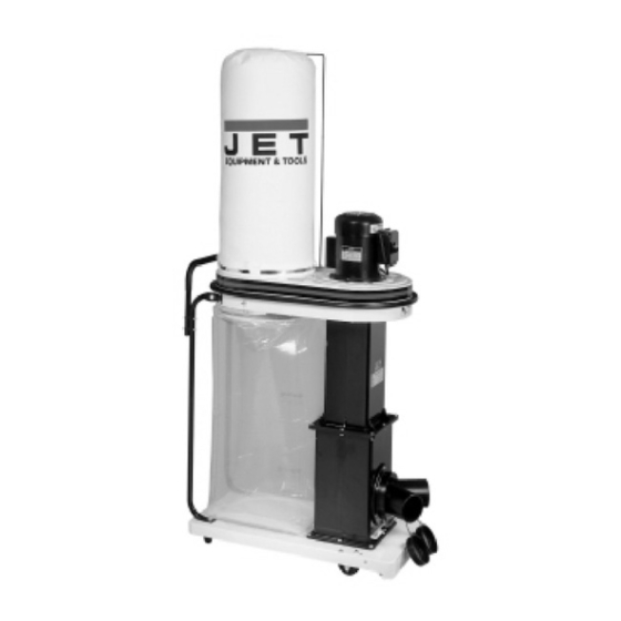
- Page 1 OWNER'S MANUAL DC-1200FS Dust Collector with Floor Sweep JET EQUIPMENT & TOOLS, INC. P.O. BOX 1349 Phone:253-351-6000 A WMH Company Auburn, WA 98071-1349 Fax: 1-800-274-6840 www.jettools.com e-mail jet@jettools.com M-708629 09/00...
-
Page 2: Warranty
JET’s warranty, then the user must bear the cost of storing and returning the product. This warranty gives you specific legal rights, and you have other rights, which vary, from state to state. JET Equipment & Tools • • • • P.O. Box 1349, Auburn, WA 98071-1349 • • • • (253) 351-6000... -
Page 3: Warnings
WARNING Read and understand the entire contents of this manual before attempting assembly or operation. Do not use this machine until proper training and knowledge has been obtained. Do not leave Dust Collector when plugged in. Unplug from outlet when not in use and before servicing. -
Page 4: Grounding Instructions
Grounding Instructions Caution! This tool must be grounded while in use to protect the operator from electric shock. In the event of a malfunction or breakdown, grounding provides a path of least resistance for electric current to reduce the risk of electric shock. This tool is equipped with an electric cord having an equipment-grounding conductor and a grounding plug. -
Page 5: Table Of Contents
Parts List ..........................13-14 Wiring Diagrams........................14-15 The specifications in this manual are given as general information and are not binding. JET Equipment & Tools reserves the right to effect, at any time and without prior notice, changes or alterations to parts,... -
Page 6: Unpacking Dc-1200Fs
WARNING Read and understand the entire contents of this manual before attempting assembly or operation of the dust collector! Failure to comply may cause serious injury! Unpacking Remove all contents from the shipping carton. Report any damage to your distributor. Do not discard any shipping material until after the dust collector has been assembled and is running properly. -
Page 7: Assembly
Assembly W ARNING The dust collector must be disconnected from the power source during assembly (unplug). Failure to comply may result in serious injury! Position the base on its side. Mount the two front, fixed casters on the base with four M6 M6x12 hex cap screws, four lock washers and four M6 flat washers, Figure 1. - Page 8 4. Press the smaller gasket (o-ring type), into the groove of the lower stand, where the inlet mounts. Attach the inlet (A, Fig. 4) to the lower stand inlet hole using six M6x12 pan head screws (B, Fig. 4). Press the larger gasket (o-ring type) into the groove of the upper stand.
- Page 9 7. With the assistance of another person lift the motor housing onto the upper stand. From the underside attach the motor housing to the upper stand using eight M6x16 hex head bolts and eight M6 lock washers (A, Fig. 7). Attach the supporting bars (A, Fig.
-
Page 10: Turning The Machine On & Off
11. Slide the hook on the bag hanger through the top loop on the filter bag. Thread the retainer strap (A, Fig. 10) through the loops on the filter bag (B, Fig.10), and tightly secure to the upper housing. The retainer strap should be tight enough to provide a good seal. - Page 11 Dryer vent hose is not acceptable for this purpose. Contact your nearest JET distributor for the full line of JET Dust Collector Hoses and Accessories. Motor Make frequent inspections of the motor and...
-
Page 12: Parts Breakdown
Parts Breakdown... -
Page 13: Parts List
Parts List for the DC-1200FS Index Part Description Size Quantity 1..427001......Upper Housing................. 1 2..427074......Pad..................2 3..427002......Impellar Guard................. 1 4..427058......Extension Guard..............1 5..427003......Gasket..................1 6..427004......Lower Housing................. 1 7..427057......Locating Pieces ............... 2 8..427005...... -
Page 14: Wiring Diagrams
55 ..ST039304 ....Tapping Screw........M3.5x12....11 56 ..ST040200 ....Tapping Screw........M4x10...... 28 57 ..TS-1550041 ....Flat Washer...........M6 ......13 58 ..TS-1550061 ....Flat Washer...........M8 ......6 59 ..TS-1550071 ....Flat Washer...........M10......2 60 ..WF164030 ....Flat Washer...........M16......1 61 ..TS-1551041 ....Spring Washer........M6 ......33 62 ..TS-1551061 .... -
Page 15: Wiring Diagrams
Wiring Diagram...
Need help?
Do you have a question about the DC-1200FS and is the answer not in the manual?
Questions and answers