Table of Contents
Advertisement
Quick Links
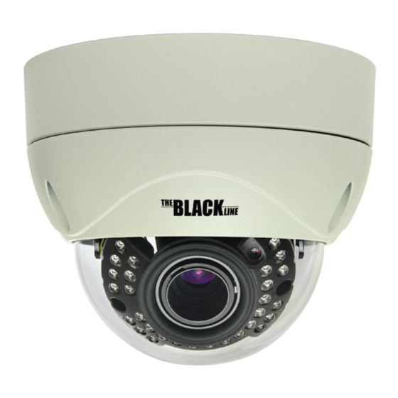
BLK-CPV700RH High Performance 700TVL
Extended Temperature Range Vandal-proof
CCTV Dome Camera User Manual
Products: BLK-CPV700RH
BLK-CPV700RH camera
Please read this manual before using your camera, and always follow the instructions for
safety and proper use. Save this manual for future reference.
BLK-CPV700RH_CM
12/9/13
Advertisement
Table of Contents

Related Manuals for Black BLK-CPV700RH


Summary of Contents for Black BLK-CPV700RH
- Page 1 BLK-CPV700RH High Performance 700TVL Extended Temperature Range Vandal-proof CCTV Dome Camera User Manual Products: BLK-CPV700RH BLK-CPV700RH camera Please read this manual before using your camera, and always follow the instructions for safety and proper use. Save this manual for future reference.
- Page 2 Changes or modifications not expressly approved by the manufacturer could void the user’s authority to operate the equipment. WARNING To prevent electric shock and risk of fire hazards, do NOT use other than the specified power source. CAUTION REGULATORY NOTICE This device complies with Part 15 of the FCC Rules.
-
Page 3: Table Of Contents
Table of Contents SECTION 1 Introduction ............... 1 1.1 Features . - Page 4 Precautions This camera should be installed by qualified personnel only. • There are no user serviceable parts inside. • Do not disassemble this camera other than to make initial adjustments. • Use a UL approved regulated 24 volt AC or 12 volt DC power supply. •...
-
Page 5: Introduction
This high performance extended temperature CCTV dome camera feature a very high resolution CCD sensor providing 700 TVL, dual voltage range (24 Vac, 12 Vdc), and on-screen display (OSD) for control and setup. The BLK-CPV700RH camera features a vandal-proof case and is weather-proof with a cold temperature range to -40 °F. -
Page 6: What's In The Box
SECTION 1: INTRODUCTION Zoom adjustment Focus adjustment BLK-CPV700RH zoom - focus adjustment knobs 1.1.1 What’s in the box Your camera includes the following: Camera assembly • Four (3) coarse-threaded screws and wall inserts to secure the base to the mounting surface •... -
Page 7: Installation
SECTION 1: INTRODUCTION SECTION 2 Installation 2.1 General Guidelines The camera can be mounted on a flat surface (surface mounted, usually on a ceiling). The camera drop cable can be routed through a hole in the ceiling, or through a cable channel on the side of the camera base. Following are some general guidelines for installing the camera. - Page 8 SECTION 2: INSTALLATION When the camera is surface mounted, the drop cable can be routed through a hole within the perimeter of the base, or through the cable channel on the side. Determine (and acquire, if needed) the best type of fasteners for attaching the camera to the mounting surface. The mounting screws and wall inserts provided are adequate for most surfaces.
-
Page 9: Camera Field Of View Adjustments
SECTION 2: INSTALLATION Video female BNC connector Extension cables To a 12 Vdc or 124 Vac regulated power supply Attach the far end of the power extension cable to a 12 Vdc or 24 Vac power source. Apply power to the camera. Verify that video from the camera can be seen on the video monitor. 2.2.1 Camera field of view adjustments In this procedure, point the camera at your surveillance (field of view) target and adjust zoom and focus. - Page 10 SECTION 2: INSTALLATION Tilt set screw Pan adjustment Tilt adjustment Tilt angle Adjust the camera Rotation to align the horizon in the video image. Camera rotation Adjust the camera zoom and focus to frame and clarify the image. Turn each adjustment knobs counterclockwise to loosen, push right or left to produce the best image, then turn the knob clockwise to tighten.
-
Page 11: Osd Software Setup
SECTION 3: OSD SOFTWARE SETUP SECTION 3 OSD Software Setup The OSD (On Screen Display) software setup menus can be viewed from the camera video output or through the VIDEO TEST port on the OSD Control board. The OSD control board is accessible when the camera dome is remove. Configuration settings are made using the OSD joystick (see photo below). - Page 12 SECTION 3: OSD SOFTWARE SETUP MAIN MENU 1st Sub MENU 2nd Sub MENU 3rd Sub MENU 4th Sub MENU AUTO IRIS, M O D E SHUT+AUTO IRIS H I G H L U M I N A N C E B R I G H T N E S S (0 0 0 ~ 2 55 ) AU TO...
- Page 13 SECTION 3: OSD SOFTWARE SETUP MAIN MENU 1st Sub MENU 2nd Sub MENU 3rd Sub MENU 4th Sub MENU M I R R O R O F F, O N B R I G H T N E S S (0 0 0 ~ 2 55 ) CO N T R A S T (0 0 0 ~ 2 55 )
-
Page 14: Important Note
SECTION 3: OSD SOFTWARE SETUP MAIN MENU 1st Sub MENU 2nd Sub MENU 3rd Sub MENU 4th Sub MENU 1/4, 2/4, 3/4, 4/4 (000 ~ 244) AREA SEL BOTTOM LEFT (000 ~ 474) RIGHT (000 ~ 474) P R I VAC Y CO LO R (1 ~ 8) 0 . -
Page 15: Osd Description
SECTION 3: OSD SOFTWARE SETUP 3.2 OSD Description LENS The LENS options include two modes: MANUAL and AUTO. In MANUAL mode, the camera uses an automatic electronic shutter. In AUTO mode, you can set the mechanical lens to fully OPEN, fully CLOSED, or automatically controlled by the camera. SPEED sets set the convergence speed of the mechanical iris. -
Page 16: Motion Detection
SECTION 3: OSD SOFTWARE SETUP PIC ADJUST Use PIC (picture) ADJUST to improve the live view image from the camera. Adaptive Tone-curve Reproduction (ATR) provides gradation compensation to improve the contrast of subjects when both low luminance areas and high luminance areas exist in the same picture. You can adjust the ATR luminance and contrast levels in the ATR submenus . -
Page 17: Cleaning
SECTION 4: CLEANING SECTION 4 Cleaning Clean the camera dome with an approved glass cleaning solution and a lint free cloth. Dust can be removed from the unit by wiping it with a soft damp cloth. To remove stains, gently rub the surface with a soft •... -
Page 18: Specifications
SECTION 5: SPECIFICATIONS SECTION 5 Specifications Table 2. Component Specifications Feature Specification Image Device 1/3" 960H Interline CCD II Scanning System 2:1 Interlace H. Resolution 700 TV Lines Scanning Frequency H:15.734 KHz, V:59.94 Hz Total Pixels 1020 (H) x 508 (V) Effective Pixels 976 (H) x 494 (V) Synchronization... - Page 19 SECTION 5: SPECIFICATIONS Feature Specification 12 Vdc (± 10 %) maximum 620 mA Power Consumption Dual voltage: 12 Vdc (±10 %) maximum 710 mA , 24 Vac (±10 %) maximum 17.3 W Operating Temperature -40 °F ~ 122 °F (-40 °C ~ +50 °C) with heater Storage Temperature -4 °F ~ 140 °F (-20 °C ~ +60 °C) Operating Humidity...
-
Page 20: Appendix A Glossary
APPENDIX A: GLOSSARY Glossary APPENDIX A Terms and definitions Term Definition Automatic Gain Control, an electronic circuit that amplifies the video signal when the strength of the signal falls below a given value. Photometric control, measures light intensity. Determines the iris reaction sensitivity. Sensitivity is increased when the potentiom- eter is turned towards PEAK, and decreased when turned towards AVERAGE. -
Page 21: Appendix B Troubleshooting
APPENDIX B: TROUBLESHOOTING APPENDIX B Troubleshooting Problem Possible Cause - Check the power connection. Nothing appears on the screen - Check the video signal cable connection to the monitor. - If the camera lens is dirty, clean it with a soft, clean cloth. - Adjust the monitor controls, if necessary. -
Page 22: Appendix C Camera Dimensions
APPENDIX C: DIMENSIONS APPENDIX C Camera Dimensions BLK-CPV700RH Ø4.44” Ø4.21” Ø5.94” Ø4.88”...
Need help?
Do you have a question about the BLK-CPV700RH and is the answer not in the manual?
Questions and answers