Table of Contents
Advertisement
Quick Links
Advertisement
Table of Contents

Related Manuals for Black BLK-CDS105NH


Summary of Contents for Black BLK-CDS105NH
- Page 2 The lightning flash with an arrowhead symbol, within an equilateral triangle is intended to alert the user to the presence of uninsulated dangerous voltage within the product's enclosure that may be of sufficient magnitude to constitute a risk of electric shock to persons. The exclamation point within an equilateral triangle is intended to alert the user to the presence of important operating and maintenance (servicing) instructions in the literature accompanying the appliance.
-
Page 3: Table Of Contents
■ Contents Features How to Use the Camera ■ Function Menu Structure Precautions ■ How to Set up the Functions ㆍLENS Components and Accessories ㆍEXPOSURE Overview ㆍWHITE BALANCE control ■ Front View ㆍBACKLIGHT ■ Side View ㆍDNR (Digital Noise Reduction) ■... -
Page 4: Features
■ Features Warning ■ The camera requires periodic inspection. Ultra High Resolution Day & Night Contact an authorised technician to carry out the inspection. By adopting a double-speed 410,000 pixel The camera identifies whether it is day or night Sony CCD, the camera produces clear picture and automatically switches to the appropriate quality with a horizontal resolution of 580 TV lines mode, depending on its environment. -
Page 5: Precautions
■ Precautions Do not drop the camera and protect Never keep the camera pointed Do not install the camera in Do not install or use the camera in an it from physical shocks. directly at strong light. extreme temperature conditions. environment where the humidity is high. -
Page 6: Components And Accessories
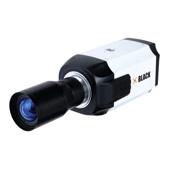
■ Components and Accessories Overview ■ Front View ① 1. Ultra High Resolution Color CCD Camera 2. Auto Iris Lens Connector Plug ③ ② 3. C-Mount Adapter ① Tripod Mounting Bracket Screw Hole Used to fix the Tripod Mounting Bracket to the top of the camera. ②... -
Page 7: Side View
■ Overview Side View Bottom View ⑤ ④ ④ Auto Iris Lens Connector Used to connect Auto Iris Lens plug. ⑤ Tripod Mounting Bracket Screw Hole Used to fix the camera on a bracket or tripod. The screw sizes for this hole are as follows: 1/4"-20 UNC (20 THREAD) L:4.5mm±0.2mm (ISO standard), or 0.197"... -
Page 8: Rear View
■ Overview Installation Procedures ■ ⑫ Auto iris lens selection switch Rear View ⑩ Change the mode to DC or VIDEO depending on the type of auto iris lens being used. REMOTE ⑬ Power IN Port Connect the power as specified for each model here. ⑭... -
Page 9: ㆍWhen Using C/Cs Mount Lens
Pin 2: NC Pin 2: Damping + Focus Control Lever of camera side after combining CS-Mount lens. Pin 3: White (Video Signal) Pin 3: Drive + Pin 4: Black (Ground) Pin 4: Drive - Lens cable No. 3 Pin connector No. -
Page 10: Connecting A Monitor
■ Installation Procedures • When Using a C Mount Lens Connecting a Monitor 1. Remove the protective glass cover at the front of this product and turn the Connect the Video OUT port on the rear panel of the camera to a monitor. CMount Adapter clockwise to install it. -
Page 11: Connecting Power
■ Installation Procedures Connecting Power Control via RS-485 Interface Since power specifications differ depending on the model, make sure to check The camera can be controlled by using external controllers like a Remote controller. your model name and specifications before connecting power. (RS-485 Communication) You can connect power as shown in the following figure. -
Page 12: How To Use The Camera
■ How to Use the Camera Function Menu Structure How to Set up the Functions You can set up functions using the 5 buttons on the rear of the camera. Setup Menu LENS • DC • VIDEO • MANUAL REMOTE UP button SET button •... - Page 13 ■ How to Use the Camera ● DC/Video : Select Auto Iris Lens MAIN SETUP Select the function using 1. LENS Change the status using • When DC is selected, you can control screen brightness. The range the UP or DOWN button. the LEFT or RIGHT button.
- Page 14 ■ How to Use the Camera EXPOSURE Note • To produce better results with A.FLK, do not use it in conjunction with MAIN SETUP the WDR mode of the BACKLIGHT menu. 1. LENS • When the SHUTTER is set to ESC after selecting the Internal 2.
- Page 15 ■ How to Use the Camera White Balance (White Bal.) Note • White Balance may not work properly under the following conditions. Use the White Balance function to adjust the screen color. In this case select the AWC mode. 1. When the SETUP menu screen is displayed, select ‘White Bal.’ by using the ①...
- Page 16 ■ How to Use the Camera ● BLC : Enables a user to directly select a desired area from a picture, and Note to view the area more clearly. • Because there can be a difference in the effectiveness of HLC according to the amount of light area in the screen, optimize the installation angle for the best HLC performance.
-
Page 17: ㆍDay/Night
● COLOR : The picture is always displayed in color. ● B/W : The picture is always displayed in black and white. ● AUTO : The mode is switched to Color in a normal environment, but switches to B/W mode when ambient illumination is low. -
Page 18: ㆍImage Adj
■ How to Use the Camera ● D-ZOOM : You can use a digital zoom of x1~x10. IMAGE ADJ. 1. When the SETUP menu screen is displayed, select ‘IMAGE ADJ.’ by using the Up and Down buttons so that the arrow indicates IMAGE ADJ. MAIN SETUP 1. - Page 19 ■ How to Use the Camera ② Set it to ‘ON’ by using the Left and Right buttons. SPECIAL 1. When the SETUP menu screen is displayed, select ‘SPECIAL’ by using the Note Up and Down buttons so that the arrow indicates ‘SPECIAL’. SPECIAL •...
- Page 20 ■ How to Use the Camera ⑤ Enter a title, move the cursor to ’POS’ and press the SET button. The ① When the SPECIAL menu screen is displayed, press the Up and entered title appears on the screen. Select the position to display the title Down buttons so that the arrow indicates MOTION DET .
-
Page 21: Troubleshooting
- MASK COLOR : Determine area color. You can select Gray, Green, Red, Blue, If the guidelines do not enable you to solve the problem, contact an Black, White. authorized technician. - TRANSP : Determine the transparency of selected area as controlling number from 0 to 3. -
Page 22: Specifications
ENABLE SHARPNESS ON/OFF (Level Adjustable) IRIS Control DC / Video Day & Night COLOR / Black& White/AUTO/EXT OFF / ON Digital Zoom OFF / ON(x10) Blemish Compensation 256 point (Even 128 Point, Odd 128 Point) RS-485 (2400, 4800, 9600, 19200, 38400, 57600 bps selectable) - Page 23 ■ MEMO...
Need help?
Do you have a question about the BLK-CDS105NH and is the answer not in the manual?
Questions and answers