Table of Contents
Advertisement
Quick Links
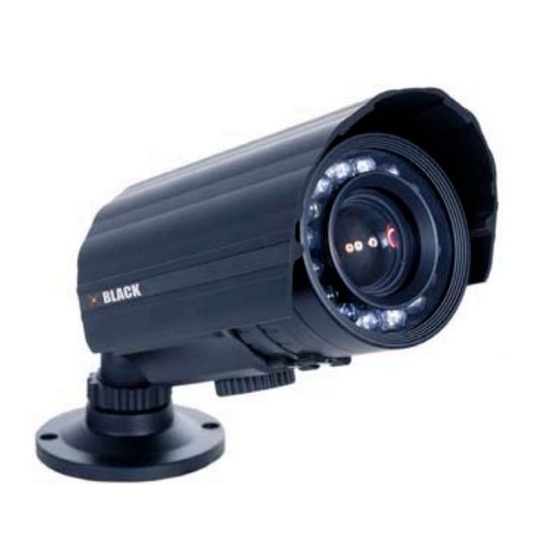
High Performance IR
Indoor/Outdoor Color CCTV
Bullet Camera User Manual
Products: BLK-CPT235VH, BLK-CPT237VH, BLK-CZT242VH,
BLK-CZT243VH
Please read this manual before using your camera, and always follow the instructions for
safety and proper use. Save this manual for future reference.
BLK-BulletCameras_CM
3/18/11
Advertisement
Table of Contents

Related Manuals for Black BLK-CPT235VH


Summary of Contents for Black BLK-CPT235VH
- Page 1 High Performance IR Indoor/Outdoor Color CCTV Bullet Camera User Manual Products: BLK-CPT235VH, BLK-CPT237VH, BLK-CZT242VH, BLK-CZT243VH Please read this manual before using your camera, and always follow the instructions for safety and proper use. Save this manual for future reference. BLK-BulletCameras_CM...
- Page 2 Changes or modifications not expressly approved by the manufacturer could void the user’s authority to operate the equipment. WARNING To prevent electric shock and risk of fire hazards: Do NOT use other than the specified power source. CAUTION REGULATORY NOTICE This device complies with Part 15 of the FCC Rules.
-
Page 3: Table Of Contents
BLK-CPT235VH . . . . . . . . . . . . . . . . . . . . -
Page 4: Precautions
Precautions This camera should be installed by qualified personnel only. • There are no user serviceable parts inside. • Do not disassemble this camera other than to make initial adjustments. • Use a UL approved regulated 24 volt AC or 12 volt DC power supply. •... -
Page 5: Introduction
SECTION 1: INTRODUCTION SECTION 1 Introduction DIGIOP Black high performance indoor/outdoor IR CCTV bullet cameras feature a very high resolution Sony CCD sensor providing ® 600 TVL, with True day/night capability, dual voltage range (24 VAC, 12 VDC), and on-screen display (OSD) for control and setup. - Page 6 SECTION 1: INTRODUCTION BLK-CPT237VH, CZT242VH Cameras BLK-CZT243VH Camera www.digiop.com...
-
Page 7: Tools You Need
SECTION 1: INTRODUCTION 1.1.1 What’s in the box Your camera includes the following: Four (4) coarse-threaded screws to secure the base plate to the mounting surface • Four (4) machined screws to secure the camera bracket to the base plate •... -
Page 8: Installation
SECTION 2: INSTALLATION SECTION 2 Installation 2.1 General Guidelines Camera Lens: Handle the camera carefully to prevent scratching or soiling the lens. If the lens or IR array shield becomes • soiled, clean it only with approved products. See the Cleaning section later in this manual. Monitor impedance: Set the monitor impedance switch to 75Ω. -
Page 9: Camera Adjustments
Apply power to the camera. If using a hand-held CCTV video setup monitor with your camera: Remove the cover to the OSD control panel by unscrewing it counter clockwise. BLK-CPT235VH OSD Control Panel BLK-CPT237VH, BLK-CZT242VH, BLK-CZT243VH OSD Control Panel Connect the BNC adapter cable to the VIDEO TEST port on the OSD control panel. -
Page 10: Bracket Adjustment
CPT237VH, BLK-CZT242VH and BLK-CZT243VH cameras for installations where the image brightness in dark conditions is still not satisfactory after performing a Software Setup of the camera. The LED LEVEL for the BLK-CPT235VH camera is not adjustable. To adjust the LED LEVEL (BLK-CPT237VH, BLK-CZT242VH and BLK-CZT243VH cameras only): Operate the camera in a dark environment. -
Page 11: Software Setup
Configuration settings are made using the OSD control panel, located on the underside of the camera. Unscrew the cover to access the controls. Depending on the model of your camera, the OSD control panel may appear as one of the following: BLK-CPT235VH OSD Control Panel BLK-CPT237VH, BLK-CZT242VH, BLK-CZT243VH OSD Control Panel Use the SETUP joy stick on the OSD control panel to navigate through the menu system. -
Page 12: Exposure
SECTION 3: SOFTWARE SETUP With the cursor pointing at the BRIGHTNESS option, rock the joystick left and right to change the setting. To return to the SETUP menu, rock the joystick down to select RETURN, then press it in. 3.2 EXPOSURE To enter the EXPOSURE submenu, highlight EXPOSURE, then press the joy stick in. - Page 13 SECTION 3: SOFTWARE SETUP When SENS-UP is activated, the increased magnification can induce noise and pixelation. NOTE RETURN: Select RET to save changes and return to the EXPOSURE menu, or END to close the SETUP menu. BLC: Backlight control. This feature enables the camera to compensate for strong back light conditions. OFF: The BLC function is disabled.
- Page 14 SECTION 3: SOFTWARE SETUP After selecting the AREA graphical submenu, a POSITION screen opens. Rock the joystick up, down, left and/or — right to position the upper-left corner of the BLC area, then push the joystick in to confirm your selection and enter the SIZE graphical submenu.
- Page 15 SECTION 3: SOFTWARE SETUP LEVEL: With the cursor pointing at LEVEL, rock the joystick right or left to increase or decrease the decrease the HSBLC level. AREA: Select AREA to enter a graphical sub-menu for defining the position and size of the part of the image where BLC is applied.
-
Page 16: White Bal
SECTION 3: SOFTWARE SETUP OFF: The D-WDR function is disabled. INDOOR: The D-WDR is preset with default LOW-LEVEL and HIGH-LEVEL settings for normal indoor lighting condition. These settings can be adjusted in the INDOOR sub-menu. RETURN: Select RET to return to the EXPOSURE menu, or END to close the SETUP menu. OUTDOOR: The D-WDR is preset with default LOW-LEVEL and HIGH-LEVEL settings for normal outdoor lighting condition. -
Page 17: Day/Night
RETURN: Select RET to return to the SETUP menu, or END to close the SETUP menu. 3.4 DAY/NIGHT The DAY/NIGHT feature is used to configure the camera to provide images in color, black and white, or either depending on lighting conditions. - Page 18 SECTION 3: SOFTWARE SETUP EXT: This EXT is selected, the DAY/NIGHT feature is not used. B/W: The picture is displayed in black and white. When B/W is used, WHITE BAL is disabled. Selecting this option opens the B/W sub-menu. BURST: Burst ON sends a color signal to the monitor in B/W mode. This signal does degrade the clarity of the image from the camera.
- Page 19 SECTION 3: SOFTWARE SETUP GAIN: With the cursor pointing to GAIN, rock the joystick right or left to increase or decrease the IR level. AREA: Select AREA to enter a graphical sub-menu for defining the position and size of the part of the image where IR SMART is applied.
-
Page 20: 3Dnr
SECTION 3: SOFTWARE SETUP N g D (AGC): This option sets the AGC brightness when switching from night to day. The recommended setting is 70. RETURN: Select RET to return to the SETUP menu, or END to close the SETUP menu. 3.5 3DNR The 3DNR feature is used to reduce the level of background noise in a low luminance environment. - Page 21 SECTION 3: SOFTWARE SETUP CAM TITLE: This feature will display a user defined camera name on the image. OFF: When OFF is selected, the camera title is not displayed. ON: Selecting ON opens the CAMERA TITLE display where the title can be specified. On the camera title screen: To enter a character in the title at the cursor position, rock the joystick up, down, left and right to highlight a character —...
- Page 22 RETURN: Select RETURN to return to the D-EFFECT menu. — NEG. IMAGE: Set this option to ON to show a color-reversed or black and white-reversed image.(available on some models). RETURN: On the D-EFFECT menu, select RET to return to the SPECIAL menu, or END to close the SETUP menu.
- Page 23 SECTION 3: SOFTWARE SETUP AREA SELECT: You can configure up to four motion detect areas on the image. Each motion detect areas can be individually positioned and sized: Move the cursor to AREA SELECT, then rock the joystick right or left to select AREA1, AREA2, AREA3, or AREA4. —...
- Page 24 SECTION 3: SOFTWARE SETUP AREA SELECT: Eight (8) rectangular privacy areas can be setup on the image. These 8 areas can be positioned anywhere on image, are color coded, and can be individually enabled or disabled. To setup a privacy area: Set the cursor on AREA SELECT, then rock the joystick right or left to select any area, —...
-
Page 25: Adjust
SECTION 3: SOFTWARE SETUP SENSE-UP: Use this option to set the sensitivity for finding defects. Setting this level to x64 or x32 produces the best results. DIFF: Use this option to set the defect size from 1 to 6. START: Selecting START initiates defect repair processing. Follow the instructions on the image to complete the operation. RETURN: Select RET to return to the SPECIAL menu, or END to close the SETUP menu. -
Page 26: Reset
SECTION 3: SOFTWARE SETUP RETURN: Rock the joystick to select RET, to return to the SETUP menu, or END, to close the menu system. RETURN: In the ADJUST menu, select RET to return to the SETUP menu, or END to close the SETUP menu. 3.8 RESET Use RESET to revert the camera configuration settings to the factory default values. - Page 27 SECTION 3: SOFTWARE SETUP High Performance IR CCTV Bullet Camera User Manual...
-
Page 28: Cleaning
SECTION 4: CLEANING SECTION 4 Cleaning Clean the camera dome with an approved glass cleaning solution and a lint free cloth. Dust can be removed from the unit by wiping it with a soft damp cloth. To remove stains, gently rub the surface with a soft •... -
Page 29: Specifications
SECTION 5: SPECIFICATIONS SECTION 5 Specifications Table 1. Component Specifications BLK-CPT237VH/ Component BLK-CPT235VH BLK-CZT243VH BLK-CZT242VH Sensor 1/3” SONY Super HAD CCD Total Pixels 811(H) * 508(V) Effective Pixels 768(H) * 494(V) Scanning System 2:1 interlace Synchronization Internal Available Backlight OFF / HSBLC / BLC selectable... - Page 30 SECTION 5: SPECIFICATIONS BLK-CPT237VH/ Component BLK-CPT235VH BLK-CZT243VH BLK-CZT242VH Operating Temperature/ -4˚F ~ 140 ˚F (-20˚C ~ +60˚C). RH 95% Max. Humidity Storage Temperature/Humidity -4˚F ~ 140 ˚F (-20˚C ~ +60˚C). RH 95% Max. Dimension 2.68” (W) * 3.82” (H) * 9.45” (D) 3.46”...
-
Page 31: Appendix A Troubleshooting
APPENDIX A: TROUBLESHOOTING APPENDIX A Troubleshooting Problem Possible Cause Nothing appears on the screen - Check the power connection. - Check the video signal cable connection to the monitor. The video image is dim or not clear. - If the camera lens is dirty, clean it with a soft, clean cloth. - Adjust the monitor controls, if necessary. -
Page 32: Appendix B Camera Dimensions
APPENDIX B: CAMERA DIMENSIONS APPENDIX B Camera Dimensions BLK-CPT235VH 9.45” 360° 180° 360° 2.68” www.digiop.com... -
Page 33: Blk-Cpt237Vh And Blk-Czt242Vh
APPENDIX B: CAMERA DIMENSIONS BLK-CPT237VH and BLK-CZT242VH 9.65” 360° 180° 360° 3.46” High Performance IR CCTV Bullet Camera User Manual... -
Page 34: Blk-Czt243Vh
APPENDIX B: CAMERA DIMENSIONS BLK-CZT243VH 11.42” 7.40” 360° 180° 360° 6.30” 3.94” 3.46” www.digiop.com...
Need help?
Do you have a question about the BLK-CPT235VH and is the answer not in the manual?
Questions and answers