Table of Contents
Advertisement
Quick Links
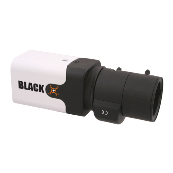
690 TVL WDR CS Mount Camera
Quick Installation Guide
This document guides you through the basic steps to install your DIGIOP™ Black
BLK-CWS208NH camera. The camera is designed for CS type lenses, and C-type lenses
with an adapter. The lens is not included. The camera features:
Ultra-compact box size with CS mounting
•
1/3" Pixim Digital Pixel System WDR sensor and DSP
•
Resolution 690 HTVLe
•
Sensitivity 0.1 Lux (F1.2, 50 IRE, 30 fps, 2850°K Color)
•
Programmable OSD via optional BLK-UTCR controller
•
Selectable Progressive Scan
•
BLK-DWS208NH camera with ED-IR pro lens
Precautions
Please read this manual carefully before installing the camera.
•
Precision components are contained in this camera. Avoid violent vibrations during installation and
•
maintenance. Do not connect the power until you have completed the installation.
Obey all local electrical wiring regulations when using this unit.
•
Do not use abrasive or corrosive materials for cleaning. Use only a soft cloth for cleaning.
•
To prevent damage to the lens and sensor, do not point the camera directly into the sun or toward
•
a strong light source.
Operate the camera only within the recommended temperature and humidity ranges.
•
Ensure that the power supply meets the current requirements of the camera and that the supply
•
voltage is inside the tolerances of the camera.
Ensure that the mounting hardware is adequate to support the weight of camera and lens.
•
Do not dismantle or service the camera. Refer it to qualified service personnel for repair.
•
Connections
All connections to the camera are make at the back panel.
Attaching the lens
1.
Remove the protective cap covering the camera image sensor.
2.
Attach the lens assembly to the camera by screwing it clockwise onto the camera mounting ring
until it is fully seated.
Connector for CS bracket (top and bottom)
Camera Body
3.
If the lens assembly has an auto-iris feature, attach the lens cable to the lens connector on the
back of the camera.
1
www.digiop.com
Video out connector (75Ω BNC): Connect
to a monitor, DVR, etc.
IRIS: Lens connector for auto- Iris lens.
LED power indicator: Illuminated when
power is applied.
Power input: 12 VDC or 24 VAC.
Mounting Ring
Lens
Set Screw
Installing the camera
1.
Install the camera mounting bracket using the instructions provided with the bracket.
2.
Attach the camera to the mounting bracket.
3.
Route a video/power extension cable between the camera and a video monitor and power
source.
4.
Apply power to the camera. NOTE: When connecting 12 VDC power, observe the polarity
marked on the power input connector
5.
While observing video from the camera on the monitor, aim the camera at your surveillance
target.
6.
Adjust the lens focus and zoom if controls are provided. If you installed a fixed lens to the camera,
you can adjust the focus by:
a.
Loosing the set screw on the side of the camera (see photo above).
b.
Slowly rotate the mounting ring until the best focus is achieved.
c.
Tighten the set screw.
Using the BLK-UTCR controller
The camera is supplied in a
Camera
general configuration that
will suit the most installation
requirements. Should advanced
configuration be required,
the optional BLK-UTCR (up
the coax) Controller may be
connected to the camera
to access the camera On
Screen Display (OSD) for user
programming.
1.
Connect the BLK-UTCR controller BNC male connector to the VIDEO OUT connector of the camera.
2.
Connect the BLK-UTCR controller BNC female connector to a display monitor.
3.
Activate the camera OSD by pressing the controller joystick button for 2 seconds. The controller is
activated when the LED lights.
In general, you can navigate through the OSD menus as follows.
Push the joystick pq to select a menu from the list.
•
Push the joystick tu to change the selected value.
•
Press down on the joystick button to call the sub-menu or execute a command.
•
To return to the previous menu, select "Previous Page", then press the joystick down.
•
NOTE: For more information, refer to the BLK-UTCR quick instruction guide provided with the controller.
OSD Menus
With the BLK-UTCR controller in-line with the video signal, press the joystick in to open the MAIN
MENU.
Monitor
BNC Male
Connector
BNC Female
Connector
LED
Joystick
Controller
The OSD MAIN MENU provides links to submenus. Submenu
links are indicated by the " .. " string at the end of the line.
Select Previous Page to return to the Main Menu. Other
parameters are defined below.
BLK-CWS208NH_CQ
Advertisement
Table of Contents

Related Manuals for Black DIGIOP BLK-CWS208NH


Summary of Contents for Black DIGIOP BLK-CWS208NH
-
Page 1: Quick Installation Guide
Quick Installation Guide Attach the camera to the mounting bracket. This document guides you through the basic steps to install your DIGIOP™ Black BLK-CWS208NH camera. The camera is designed for CS type lenses, and C-type lenses Route a video/power extension cable between the camera and a video monitor and power with an adapter. - Page 2 WB Offset: this modifies AWB performance in images with minimal color content, to compensate Mask Color: Black, White, or Red. Sets the color of any enabled privacy masks. • • for unsatisfactory color metering.
Need help?
Do you have a question about the DIGIOP BLK-CWS208NH and is the answer not in the manual?
Questions and answers