Advertisement
Quick Links
™
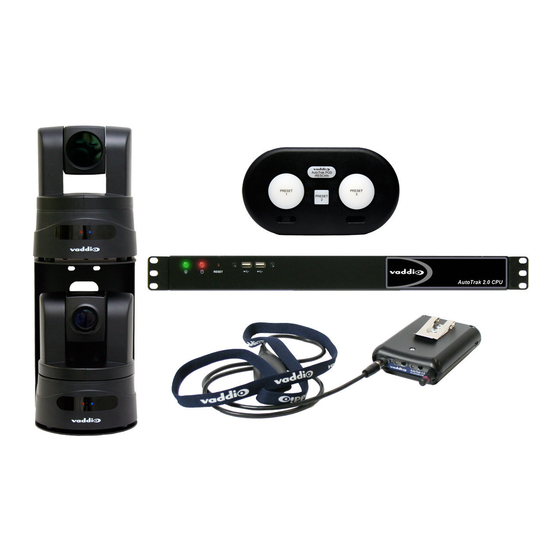
Vaddio™ AutoTrak™ 2.0
Camera Tracking System featuring Automatic Pan/Tilt/Zoom
Camera Tracking
Optional:
EasyTalk AutoTrak 2.0 Wireless Audio Interface:
998-7230-000: EasyTalk AutoTrak 2.0 Wireless Audio Interface - North America
998-7230-001: EasyTalk AutoTrak 2.0 Wireless Audio Interface - International
©2014 Vaddio - All Rights Reserved. AutoTrak 2.0 with Optional EasyTalk Wireless Audio Interface - Document 342-0382 Rev. E
Part Numbers:
AutoTrak 2.0
Camera Tracking System: North America
999-7250-000
:
AutoTrak 2.0-Dual HD-18 Kit with
Quick-Connect DVI/HDMI Interface-North America
999-7260-000
: AutoTrak 2.0-HD-18 & HD-20 Kit with
Quick-Connect DVI/HDMI Interface-North America
AutoTrak 2.0
Camera Tracking System: International
999-7250-001
:
AutoTrak 2.0-Dual HD-18 Kit with
Quick-Connect DVI/HDMI Interface-International
999-7260-001
: AutoTrak 2.0-HD-18 & HD-20 Kit with
Quick-Connect DVI/HDMI Interface-International
I
U
NSTALLATION AND
G
SERS
UIDE
Advertisement

Related Manuals for VADDIO AutoTrak 2.0


Summary of Contents for VADDIO AutoTrak 2.0
- Page 1 EasyTalk AutoTrak 2.0 Wireless Audio Interface: 998-7230-000: EasyTalk AutoTrak 2.0 Wireless Audio Interface - North America 998-7230-001: EasyTalk AutoTrak 2.0 Wireless Audio Interface - International ©2014 Vaddio - All Rights Reserved. AutoTrak 2.0 with Optional EasyTalk Wireless Audio Interface - Document 342-0382 Rev. E...
- Page 2 AutoTrak 2.0 Camera Tracking System Inside Front Cover - Blank Inside Front Cover - Blank AutoTrak 2.0 Camera Tracking System - Document Number 342-0382 Rev. E Page 2 of 52...
- Page 3 Each system includes a dual camera mount which can be wall mounted or mounted on top of the Vaddio Edge series video carts.
- Page 4 UNPACKING: Carefully remove all of the parts for the AutoTrak 2.0 999-7250-000 Dual HD-18 Kit with Quick Connect DVI/HDMI Interface (North America Only) packaging: One (1) AutoTrak 2.0 CPU (closed system preloaded with AutoTrak 2.0 software and video card) ...
- Page 5 AutoTrak 2.0 Camera Tracking System UNPACKING: Carefully remove all of the parts for the AutoTrak 2.0 999-7250-001 (Int’l) Dual HD-18 Kit with Quick Connect DVI/HDMI Interface) packaging: One (1) AutoTrak 2.0 CPU (closed system preloaded with AutoTrak 2.0 software and video card) ...
- Page 6 (2) PS/2 interfaces for keyboard/mouse, 16GB Compact Flash and Video capture card. Note: The AutoTrak 2.0 CPU may be subject to change in cosmetics due to the extraordinarily turbulent nature of the PC industry, parts availability and model year upgrades. If changes are made, Vaddio will be certain to make changes in the documentation accordingly.
- Page 7 AutoTrak 2.0 Camera Tracking System The IR Lanyard and Belt Pack for use with the AutoTrak 2.0 Camera Tracking Systems: 999-7250-000 and 999-7260-000 North America 999-7250-001 and 999-7260-001 International ⑥ ⑤ ⑦ ④ ① ③ ② 1) IR Lanyard: Cloth covered flat flex circuit with IR LEDs terminates at the Central Medallion Note: Do not fold the Lanyard Necklace at any time as it contains a flexible circuit that may cease to work if the necklace is hard folded.
- Page 8 Interface. Solid blue LED indicates connection with the AutoTrak 2.0 Wireless Audio Interface. Flashing blue LED indicates radio link has been lost. Note: Radio link operates up to 100 feet line of sight of the AutoTrak 2.0 Wireless Audio Interface.
- Page 9 3) Dip Switches: There are two (2) 4-position dip switches located on the circuit board, SW4 and SW5. They provide configuration settings for Microphone Gain Control, Filtering, Compression and Microphone Filtering and Pairing of the Wireless Belt Pack to the AutoTrak 2.0 Wireless Audio Interface.
- Page 10 Radio circuit to increase battery life. Make sure this switch is in the ON position for use with Audio Interface (if applicable). It ships from the factory in the OFF position. Note: Turn OFF Dip Switch 3 when not using the optional EasyTalk AutoTrak 2.0 Wireless Audio Interface with the AutoTrak 2.0 System.
- Page 11 ④ ⑤ ⑥ ⑦ 1) Power ON/OFF: This switch turns the power for the AutoTrak 2.0 Wireless Audio Interface on or off. To use, push the power button until the blue LED is lit and the system is ready for operation.
- Page 12 The Belt Pack Wireless Microphone Audio is also sent to the PC to send to the Far End. The AutoTrak 2.0 Wireless Audio Interface will also be recognized as a USB Audio Device by the PC with recording (the Belt Pack Wireless Microphone Audio) and playback (the Speaker Audio) capabilities.
- Page 13 (10) seconds of pressing the pairing button SW3 on the Belt Pack or pairing will not occur! D. Press the Pair Button on the front panel of the EasyTalk AutoTrak 2.0 Wireless Audio Interface. E. The Belt Pack and the AutoTrak 2.0 Wireless Audio Interface will automatically sync with each other.
- Page 14 AutoTrak 2.0 Camera Tracking System Basic System Configuration 1: AutoTrak 2.0 999-7250-000 Dual HD-18 Kit with Quick Connect DVI/HDMI Interface (North America Only) AutoTrak 2.0 Quick-Connect HD-18 Box 998-1105-020 IR Reference AutoTrak 2.0 IR Lanyard, Cat-5e Camera with attached cable, Rechargeable...
- Page 15 AutoTrak 2.0 Camera Tracking System Basic System Configuration 2: AutoTrak 2.0 999-7260-000 HD-18 IR Reference Camera and HD-20 Tracking Camera Kit with Quick Connect DVI/HDMI Interface (North America Only) AutoTrak 2.0 Quick-Connect HD-18 Box 998-1105-020 IR Reference Cat-5e AutoTrak 2.0 IR Lanyard,...
- Page 16 One More Time: The AutoTrak 2.0 CPU is a computer running a Linux OS. Please do not remove power from the AutoTrak 2.0 CPU without first shutting the system down, as you would any other business computer. It is safe to remove power only after the AutoTrak 2.0 CPU has been shut down.
- Page 17 Booting up the System and Initial Set-up: ith the AutoTrak 2.0 Belt Pack on (at least the system power switch on) and the lanyard plugged into the belt pack (with the battery fully charged), place the lanyard/belt pack in a centered location approximately 20’...
- Page 18 AutoTrak 2.0 Camera Tracking System Note: If AutoTrak 2.0 CPU green light is blinking (which indicates standby mode), restart system by: Turn the rear mounted Power Switch OFF for a few seconds and then back ON - or - remove CPU power and then restore it - or - push the recessed Restart Button for a few seconds and then release it.
- Page 19 If the lanyard is not in the shot when tracking resumes, the IR Reference will then search for the lanyard. AutoTrak 2.0 Camera Tracking System - Document Number 342-0382 Rev. E Page 19 of 52...
- Page 20 ① ② ③ ⑨ ⑥ ④ ⑦ ⑤ ⑩ ⑨ ⑧ ⑧ 8) To start AutoTrak 2.0 click the Resume button. AutoTrak 2.0 Camera Tracking System - Document Number 342-0382 Rev. E Page 20 of 52...
- Page 21 Using the AutoTrak 2.0 as an Input to the AutoPresenter for Camera Presets (If the AutoTrak 2.0 and AutoPresenter are not being used together in a system – skip this section) AutoTrak 2.0 Tracking Camera presets require configuration in both AutoTrak 2.0 and AutoPresenter.
- Page 22 1) In the AutoPresenter Menus, select the menu item “AutoTrak 2.0 Input” and select which input (1-6) to which the AutoTrak 2.0 will be connected. This way up to six (6) trigger inputs, between 1 and 72, can be dedicated to preset positions for the AutoTrak 2.0 Tracking Camera. These presets can be incorporated into the system and use the Vaddio trigger devices such as PresenterPOD, StepVIEW mats, AutoVIEW IR Sensors, MicVIEW push to talk mics or TouchVIEW RF buttons.
- Page 23 Updating the System Software - AutoTrak 2.0 to AutoTrak 2.0: 1) To update the AutoTrak 2.0 system software, contact Vaddio Tech Support or go to the Vaddio website to get the Zip File. Copy the file to Root Directory of USB Flash Drive (not included).
- Page 24 AutoTrak 2.0 Camera Tracking System All Menu Screen Shots and Control Descriptions: Tracking/Main Page Control Action Description Pause/Resume Button Click/Press Stop/Interrupt tracking Shutdown Button Click/Press Close/Shutdown system AutoTrak 2.0 Camera Tracking System - Document Number 342-0382 Rev. E Page 24 of 52...
- Page 25 System Reference Custom Home Check Allows the Setting of a different Default Camera Home Position Pause/Resume Button Click/Press Pause or Return to Tracking Shutdown Button Click/Press Close/Shutdown System AutoTrak 2.0 Camera Tracking System - Document Number 342-0382 Rev. E Page 25 of 52...
- Page 26 Close/Shutdown system Note 1: AutoPresenter Presets Trigger Number “0” denotes no presets present. Note 2: Status bar shows the Tracking Camera Pan/Tilt/Zoom positions and Pan/Tilt Speeds. AutoTrak 2.0 Camera Tracking System - Document Number 342-0382 Rev. E Page 26 of 52...
- Page 27 Tilt Speed Click/Press Up/Down Select Tilt Speed Save Button Click/Press Save Pan/Tilt Speeds Pause/Resume Button Click/Press Pause or Return to Tracking Shutdown Button Click/Press Close/Shutdown system AutoTrak 2.0 Camera Tracking System - Document Number 342-0382 Rev. E Page 27 of 52...
- Page 28 Click/Press Load all tuning setting Save Button Click/Press Save all tuning setting Pause/Resume Button Click/Press Pause or Return to Tracking Shutdown Button Click/Press Close/Shutdown system AutoTrak 2.0 Camera Tracking System - Document Number 342-0382 Rev. E Page 28 of 52...
- Page 29 Loads previously saved settings Save Button Click/Press Saves tuning settings for IR Reference Camera Pause/Resume Click/Press Pause or Return to Tracking Button Shutdown Click/Press Close/Shutdown system Button AutoTrak 2.0 Camera Tracking System - Document Number 342-0382 Rev. E Page 29 of 52...
- Page 30 Saves tuning settings for Tracking Camera NOTE: Bright, natural sunlight contains too much IR and can hinder AutoTrak 2.0’s ability to discern the lanyard from the surroundings. Consideration of the room environment is crucial to optimal performance. AutoTrak 2.0 Camera Tracking System - Document Number 342-0382 Rev. E...
- Page 31 If the Restore Factory Defaults button is selected, then the “Are You Sure” dialog box will pop up to protect the previously stored presets and make sure that resetting to the factory defaults is truly intended. AutoTrak 2.0 Camera Tracking System - Document Number 342-0382 Rev. E Page 31 of 52...
- Page 32 If the Restore Factory Defaults button is selected, then the “Are You Sure” dialog box will pop up to protect the previously stored presets and make sure that resetting to the factory defaults is truly intended. AutoTrak 2.0 Camera Tracking System - Document Number 342-0382 Rev. E Page 32 of 52...
- Page 33 AutoTrak 2.0 Camera Tracking System Control Parameter Descriptions: Definitions of the terminology used in the AutoTrak 2.0 Software Luminance This is the minimum IR brightness level indicating the IR lanyard is present in the video Threshold frame. The actual value is calculated from the video capture data received from the camera.
- Page 34 Camera Select This parameter is used select either the AutoTrak 2.0 HD-18 or AutoTrak 2.0 HD-20 as the Tracking Camera (Iris values are different between cameras). Note: The HD-18 is always the reference camera.
- Page 35 A rotary switch allows the user to choose the component HD output video resolution and format. See Page 39-40 for additional information on switch settings. 8) 12 VDC Input NOTE: The power input is not used with the AutoTrak 2.0 system. This is only used on the standard, ClearVIEW HD-18 camera. 9) YPbPr Video Output: Component HD video is fed through the DB-15 connector.
- Page 36 AutoTrak 2.0 Camera Tracking System Details on the Vaddio AutoTrak 2.0 HD-20 Pan/Tilt/Zoom Camera used in the AutoTrak 2.0 Systems: Camera Features: ① 1) Camera/Sensor/Optics: 6.49mm diagonal (1/2.8-Type) high speed CMOS image sensor with 3.27M pixels is combined with a 20x optical zoom lens for capturing truly precise and clean HD video.
- Page 37 A rotary switch allows the user to choose the component HD output video resolution and format. See Pages 40-41 for additional information on switch settings. 8) 12 VDC Input NOTE: The power input is not used with the AutoTrak 2.0 system. This is only used on the standard, ClearVIEW HD-20 camera. 9) HDMI Output: The HDMI output feeds out HD digital video only (no copy protect or device communication is included).
- Page 38 These switch settings must be set in accordance with the peripherals used in the system. For the AutoTrak 2.0, the required settings are noted. On the bottom of the camera there is a label that defines the 10-positon dip switch functions and the rotary HD/YPbPr Video Select switch.
- Page 39 These switch settings must be set in accordance with the peripherals used in the system. For the AutoTrak 2.0, the required settings are noted. On the bottom of the camera there is a label that defines the 10-positon dip switch functions and the rotary HD/YPbPr Video Select switch.
- Page 40 1.0 monitors only. The YCbCr color space is best for HDMI digital video. Switches 8, 9 and 10: Leave up - or in the OFF position AutoTrak 2.0 Camera Tracking System - Document Number 342-0382 Rev. E Page 40 of 52...
- Page 41 Less than 299,792,458 meters per second (accounting for the index of refractivity of air - 1.0003 Antenna Connector One (1) RP-SMA connector Power Supply/Connector 12 VDC, 1.0 Amp Switching Supply, 5.5mm OD x 2.5mm ID coax receptacle on AutoTrak 2.0 Weight Approx. 3.3 lbs (1.496854821 kg) Dimensions Audio Interface 1.72”...
- Page 42 Vaddio Customer Service: Vaddio will test, repair, or replace the product or products without charge if the unit is under warranty and is found to be defective. If the product is out of warranty, Vaddio will test then repair the product or products.
- Page 43 Changes or modifications not expressly approved by Vaddio can affect emission compliance and could void the user’s authority to operate this equipment. ICES-003 Compliance This digital apparatus does not exceed the Class A limits for radio noise emissions from digital apparatus set out in the Radio Interference Regulations of the Canadian Department of Communications.
- Page 44 Operation is subject to the following two conditions: (1) This device may not cause interference, and (2) This device must accept any interference including interference that may cause undesired operation of the device. Changes or modifications not expressly approved by Vaddio can affect emission compliance and could void the user’s authority to operate this equipment. ...
- Page 45 Changes or modifications not expressly approved by Vaddio can affect emission compliance and could void the user’s authority to operate this equipment. ICES-003 Compliance This digital apparatus does not exceed the Class A limits for radio noise emissions from digital apparatus set out in the Radio Interference Regulations of the Canadian Department of Communications.
- Page 46 Operation is subject to the following two conditions: (1) This device may not cause interference, and (2) This device must accept any interference including interference that may cause undesired operation of the device. Changes or modifications not expressly approved by Vaddio can affect emission compliance and could void the user’s authority to operate this equipment.
- Page 47 Operation is subject to the following two conditions: (1) This device may not cause interference, and (2) This device must accept any interference including interference that may cause undesired operation of the device. Changes or modifications not expressly approved by Vaddio can affect emission compliance and could void the user’s authority to operate this equipment.
- Page 48 Operation is subject to the following two conditions: (1) This device may not cause interference, and (2) This device must accept any interference including interference that may cause undesired operation of the device. Changes or modifications not expressly approved by Vaddio can affect emission compliance and could void the user’s authority to operate this equipment. ...
-
Page 49: Ezcamera Power & Hd Video Rj-45 Connector Pin-Outs
Set the Tracking Camera position and store the preset. Recall the preset with the commands above. The Preset OFF command must be issued to return to active tracking. R99<lf> Will reset/reboot the AutoTrak CPU AutoTrak 2.0 Camera Tracking System - Document Number 342-0382 Rev. E Page 49 of 52... - Page 50 AutoTrak 2.0 Camera Tracking System AutoTrak 2.0 HD-18 PTZ Camera Dimensions AutoTrak 2.0 HD-20 PTZ Camera Dimensions AutoTrak 2.0 Camera Tracking System - Document Number 342-0382 Rev. E Page 50 of 52...
- Page 51 * To allow for full tilt movement of the upper (Reference) HD-18 camera, an overall “build out” height of 20” is suggested AutoTrak System Notes: AutoTrak 2.0 Camera Tracking System - Document Number 342-0382 Rev. E Page 51 of 52...
- Page 52 Toll Free: 800-572-2011 ▪ Phone: 763-971-4400 ▪ FAX: 763-971-4464 www.vaddio.com ©2014 Vaddio - All Rights Reserved. Reproduction in whole or in part without written permission is prohibited. Specifications and pricing are subject to change without notice. Vaddio, AutoTrak, AutoPresenter, Quick-Connect, ClearVIEW, WallVIEW, EZCamera, HSDS and PowerRite are registered trademarks of Vaddio.
Need help?
Do you have a question about the AutoTrak 2.0 and is the answer not in the manual?
Questions and answers