Lowrance HDS-5x Operation Manual
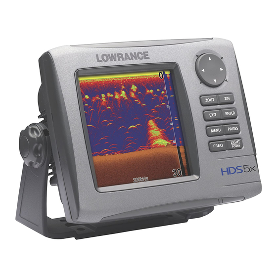
Fish finding sonar
Hide thumbs
Also See for HDS-5x:
- Operation manual (101 pages) ,
- Quick start manual (4 pages) ,
- Operation manual (91 pages)
Table of Contents
Advertisement
Advertisement
Table of Contents

Subscribe to Our Youtube Channel
Related Manuals for Lowrance HDS-5x


Summary of Contents for Lowrance HDS-5x
- Page 1 Инструкция Lowrance HDS-5x GEN2 Перейти в карточку товара 8 800 775 98 98...
- Page 2 988-0176-00B HDS-5x Fish Finding Sonar Operations Guide...
-
Page 3: Table Of Contents
Contents Table of contents Introduction ..................3 Getting Started ................. 5 Turning on the Unit ..................5 Keypad ....................... 5 Backlight ....................5 Cursor ......................5 Language ....................5 Menus ......................6 Selecting a Fishing Mode ................6 Entering Letters in Text Boxes ..............7 Restore Defaults .................. - Page 4 Contents Radar Operation ................37 ..................... 37 Cursor position window................43 Radar Overlay ..................43 Settings Menu ................. 45 Sonar Settings Menu ................52 Manual Mode ................... 53 Fishing Modes ..................54 Installation Menu ..................55 Keel Offset ....................55 Radar Settings Menu ................
-
Page 5: Introduction
Introduction Introduction Thank you for purchasing from Lowrance, the industry leader in marine technology. This manual is packaged with a Quick Start Guide, Installation Guide, License and Warranty booklet and NMEA 2000 Networks Installation Instructions. If any of these documents are missing, you may acquire them via a free download at www. - Page 6 Introduction Lowrance HDS-5x Sonar ZOUT: MOB: KEYPAD cursor, scroll through ENTER view sonar/GPS history shortcut key for functions like saving a waypoint at cursor EXIT: cancels position entries, closes PAGES: opens Pages cursor position and chart location on Chart page...
-
Page 7: Getting Started
Getting Started Getting Started Turning on the Unit Press the POWER/LIGHT key to turn on the unit. If the unit is not connected to a transducer, the unit will start up in simulator mode. To turn off the unit, press the POWER/LIGHT key for three seconds. Keypad Keypad This unit’s keypad can be used in two ways. -
Page 8: Menus
Getting Started Menus This unit has a Settings menu, a Pages screen and several context menus. The Settings menu provides access to the settings menus for the three main operation modes: Sonar and Radar. The Settings menu is accessed by pressing MENU twice. The Pages screen allows you to select a page to be shown on the display. -
Page 9: Entering Letters In Text Boxes
Getting Started Fishing Mode Options General Use Shallow Water depths less than 100 feet Fresh Water Deep Water transducer frequency Slow Trolling Fast Trolling speed Clear Water Brackish Water lower chart speed Entering Letters in Text Boxes This unit has some features and functions that may Keypad button controls require you to enter data in a text box. -
Page 10: Restore Defaults
Getting Started Restore Defaults The Restore Defaults command switches the unit back to the settings it had when you purchased it (default settings). To Restore Defaults: Press MENU twice. Select System and press ENTER. Highlight Restore Defaults and press ENTER appear. -
Page 11: Pages Screen
Pages Pages Page icons rotate around With Sonar selected, unit will the circular display a full sonar screen Pages display options allows you to display a split screen Sonar icon rotated to center of Page Icons it is the selected page option Pages Screen Consists of four page icons that scroll horizontally around the Pages menu. -
Page 12: Data Overlay
Pages Data Overlay Data overlay is information you can display on top of the page screen, allowing you to customize each page with desired data. Every page option has its own Data Overlay menu. The menu allows you to edit, add or remove overlay data from the display. - Page 13 Pages Edit Mode When a gauge is added to the display it will be shown in edit mode. Analog and bar gauges are shaded in blue when they are in Edit Mode. Digital Gauges will be shown with a blue border. Analog gauge in edit Move or Placing a Gauge The Move gauge command allows you to move data overlay to any position on the...
- Page 14 Pages To select data overlay: 1. Press the Select data Use the keypad to select the desired category and press ENTER. A ENTER. Type Switches data overlay display between analog, digital and bar gauge formats, provided the format is appropriate for the selected data type. To change Type press the Type softkey to toggle between digital and analog gauge formats.
- Page 15 Pages Controls the number scale used on data overlay gauges and selects warning thresholds. Changing the limits on an analog or bar gauge removes unnecessary numbers from the gauge, making them easier to read. Warnings help you stay within selected warning thresholds. in the Limits text boxes —...
- Page 16 Pages Allows you to Add/Remove sources and adjust Bezel, Caption covered previously in the section. the Edit Overlay menu and press ENTER. Caption Invert Text Changes appearance of data overlay text Add Source Displays the same type of data from different sources on the same analog gauge.
- Page 17 Pages Highlight Remove source ENTER. A list of sources will appear. ENTER.
-
Page 18: Sonar Page
Pages Sonar Page Displays the water column moving from right to left on your unit’s screen. On the right side of the screen, the Amplitude Scope bar previews echoes about to appear on the display. The sonar page has three splitscreen view settings and 14 color palette settings. Sonar display options are covered in more detail in the Sonar Operation section. -
Page 19: Radar Page
Pages Radar Page Displays the PPI (Position Plan Indicator) screen, Range Rings and the cursor. The PPI can be shifted to show more of a desired portion of the screen (Look Ahead, Center & Offset) and the color palette can be changed to show returns in white, yellow, black or green. - Page 20 Pages Controls Info page data, page layout and data display format selection. To access the Data menu, press MENU while on the Info page. Dash 1, Dash 2 and Dash 3 Info Page dashboard templates that vary in page layout and in the number of gauges supported.
- Page 21 Pages To edit gauge display: Use the keypad to select the gauge you want to edit and press ENTER will appear. Use the keypad to select a data category and press ENTER GPS category ENTER. Press MENU Highlight Finish Edit and press ENTER. The Ground Speed subcategory Highlight the...
- Page 22 Pages To select data: Highlight ENTER. Select Data 2. Use the keypad to select the desired category and press ENTER appear. ENTER. To add source: Select Add Source and press ENTER. Use the keypad to select the desired category and press ENTER appear.
- Page 23 Pages To Finish Editing: Select and press ENTER. A Finish Edit Select Save and press ENTER. Change Layout Controls the gauge layout of dashboard templates and customized dashboards. That allows you to select a desired gauge layout template for all dashboards. To change layout: press ENTER.
-
Page 24: Utilities
Pages Highlight Remove Dashboard and press ENTER. Select Delete and press ENTER. dashboard list Settings Opens the Settings menu. Settings information is covered in detail in the Settings menu section. Utilities Allows you to set alarms, view sonar logs and access other system settings. - Page 25 Pages Copying a screenshot Copy File screen 1. Highlight Files ENTER. Select the desired File category and press the keypad to the right. A Press MENU. Highlight Copy and press ENTER. The Copy File screen will appear. ENTER. Highlight ENTER. Files Select the desired File category and press ENTER.
- Page 26 Pages display option You can display multiple pages at the same time by scrolling the desired page’s icon to the center of the screen and then choosing a secondary page from the list of combo page display options. displayed in the left panel. displayed in the right panel.
-
Page 27: Displaying Multiple Panels
Pages Displaying Multiple Panels Multiple panels can be displayed by setting up a combo display using a page that supports the Split feature. By displaying multiple panels, you can view more information on the screen at one time. Step 1: Select sonar split screen Select a Split view for the sonar page. - Page 28 Pages of each panel display To adjust panel sizes: the PAGES key. Press MENU. Highlight Adjust Panel Sizes ENTER. press ENTER.
-
Page 29: Sonar Operation
Sonar Sonar Operation Surface clutter Range Fish Arches scale Cursor depth Depth Line Brush Water depth, water Colorline Cursor coordinates recent sonar history echoes To access the Sonar Page: Press the PAGES key. Use the keypad to select Sonar and press ENTER. Cursor Viewing Sonar History You can review your recent sonar histo-... -
Page 30: Sonar Menu
Sonar Sonar Menu Accesses features ranging from Auto Sensitivity and Depth Range to Frequency and Stop Sonar. From the Sonar Page, press MENU to access the Sonar Menu. Sensitivity Sonar Menu Controls the level of detail shown on the display. Increasing Sensitivity will show more detail on the screen;... - Page 31 Sonar Colorline Wide yellow hard sonar return sonar returns Distinguishes strong sonar echoes from weak sonar echoes. That makes it easier for bottom. A hard return will be shown as a wide, bright yellow line, whereas a soft return will be a narrow reddish-blue line.
- Page 32 Sonar Split Zoom, Bottom Lock and Flasher. No Split — displays full sonar screen Zoom ZOOM Bottom Lock Flasher Stop Sonar Pauses the sonar chart, allowing you to get a closer look at sonar echoes. Adjust Sensitivity and Colorline can also be adjusted from the Sonar menu by using the Adjust command.
-
Page 33: Sonar Options
Sonar Custom — Upper and Lower Limits Controls not only the depth range (lower limit), but also lets you choose the upper limit. So, instead of a selecting a range that includes the water surface, you can choose upper and lower limits anywhere along the water column. -
Page 34: Palette
Sonar To select a Split option: highlight Split and press ENTER. Use the keypad to select the desired option and press ENTER. Palette Sonar display color templates with varying degrees of color and brightness. On the Palette menu, you can select a sonar palette options. - Page 35 Sonar Uses a red line graph with digital display at the top of the screen to illustrate changes in Temperature. The Temperature graph makes it easier to recognize temperature trends. To turn the Temperature Graph on/off, highlight Temperature Graph on the Sonar Options menu and press ENTER.
-
Page 36: Log Sonar Data
Sonar Fish ID Depths detected; helps gauge the distance from each Both — turns on both Symbols and Depths. To select Fish ID option: Highlight Fish ID and press ENTER. Use the keypad to select Symbols, Depths or Both and press ENTER. - Page 37 Sonar press ENTER on the screen. Use the keypad to input the desired Select OK and press ENTER. Bytes per sounding To select Save to or Bytes per Sounding: Highlight Save to or Bytes per Sounding ENTER. Use the keypad to select the desired option and press ENTER.
- Page 38 Sonar To stop logging: Select Stop ENTER. The Stop Highlight the Stop Logging press ENTER. NOTE: Refer to the Utilities segment of the Pages section for...
-
Page 39: Radar Operation
Radar Radar Operation Range North Indicator Heading Line Radar orientation indicator Range Rings To access the Radar Page: Press the PAGES key. Use the keypad to select the Radar Icon and press ENTER. NOTE: You will only be able to see the Radar page if your unit is connected to a radar. -
Page 40: Adjust Menu
Radar Radar State Controls radar transmission modes: Off, Transmit and Standby. Off turns off the radar. Transmit broadcasts a radar signal and standby leaves the radar on, but does not broadcast a signal. To select Radar State: Press MENU, highlight Radar State and press ENTER. Select the desired state and press ENTER. - Page 41 Radar Sea Clutter Allows you to select the Sea Clutter adjustment mode — Auto or Manual. If you make changes to Sea Clutter when it is in auto mode (Harbor or Offshore), Sea Clutter will switch to Manual mode. Sea Clutter Options Manual Harbor Offshore...
- Page 42 Radar Position You can move the PPI (Plan Position Indicator) to different locations on the radar display. There are three Position options: Center, Look Ahead and Offset. To change the PPI position: Select the desired position and press enter. Position Default setting, will position the PPI in the center of Center the screen...
- Page 43 Radar Symbology Used to turn on/off symbols displayed on the PPI screen, including range rings, range markers and compass overlay. Rather than turn off each display feature individually, the Symbology feature allows you to remove them all at once. To toggle Symbology on/off highlight Symbology on the radar menu and press enter.
- Page 44 Radar EBL/VRM menu Places selected Electronic Bearing Line and Variable Range Marker on the display. Press the MENU key. Use the keypad to select the EBL/VRM and press ENTER. EXIT. Adjust Adjusts size and location of active EBL/VRM. EBL/VRM and press ENTER. Select Adjust and press ENTER.
-
Page 45: Cursor Position Window
Radar Cursor position window When the cursor is active on screen the Cursor position window appears in the bottom left corner of the Radar page. Cursor position window Radar Overlay Radar Overlay places radar returns on top of the map on the Chart Page. That gives you greater awareness of your surroundings by allowing you to see radar returns aligned with actual radar targets. - Page 46 Radar Blank page...
-
Page 47: Settings Menu
Settings Settings Menu settings for your unit. To access the Settings menu, press MENU twice. Settings Menu Options Fuel Vessels Page Trails Units Network System Used to change system settings like units, language and key beeps. 1. Press MENU twice. Highlight and press ENTER. -
Page 48: Key Beeps
Settings To change Text Size: Highlight Text Size ENTER. ENTER. Key Beeps By default, a tone (key beep) will sound when any key is pushed on the unit. You can change key beep volume or turn them on or off from the Key Beep menu. -
Page 49: Magnetic Variation
Settings Datum A model of the earth’s surface based on a network of surveyed ground features (points). This unit’s default datum is WGRS-84. Select ENTER. Datum ENTER. Coord System Controls the coordinate system used when position coordinates are entered and displayed. - Page 50 Settings Satellite Status Satellites Monitors the location of satellites in view and the quality of the unit’s satellite lock- on. The Satellite page has two display options. The Satellite screen displays a circular graphic that shows where satellites are located and a bar graph that monitors the strength of satellites within range of your unit.
-
Page 51: Screen Capture
Settings Screen Capture Saves images of your unit’s screen to your unit. That allows you to capture images targets. To take a screen capture: Select ENTER. Screen Capture Press the LIGHT/POWER key to capture the current screen. Repeat this step take additional screen captures. Select Files ENTER. - Page 52 Settings Restore Defaults To switch the unit back to the settings it had when you purchased it (default settings), use the Restore Defaults command. Reset Defaults will reset the unit to default settings. To Restore Defaults: Highlight ENTER. Restore Defaults Select Yes and press ENTER.
- Page 53 Settings To adjust Waypoint, Hardware, Flywheel and Radar settings : Open the desired setting (—). press Enter to turn it on/off. The center To adjust cursor settings: Highlight the desired cursor setting and press ENTER will appear. Use the arrow keys to select the desired value and press ENTER.
-
Page 54: Sonar Settings Menu
Settings Sonar Settings Menu The Sonar Settings Menu is used to modify Sonar options and display settings like Sonar Source, Noise Rejection and Fishing Mode. To access the Sonar Settings: Press MENU twice. Select Sonar and press ENTER. Sonar Settings Menu Sonar Source Selects the display unit that will be used for sonar data. -
Page 55: Manual Mode
Settings Surface Clarity Wave action, boat wakes and temperature inversion are some of the sources that can cause onscreen clutter near the surface. Surface Clarity reduces surface clutter by decreasing the sensitivity of the receiver near the surface. To adjust Surface Clarity: Select Surface Clarity Surface Clutter... -
Page 56: Fishing Modes
Settings Fishing Modes Enhances the performance of your unit by providing preset packages of sonar Interference Rejection, Surface Clarity and Ping Speed, among others. Fishing Fishing Mode Options General Use Shallow Water depths less than 100 feet Fresh Water Deep Water transducer frequency Slow Trolling Fast Trolling... -
Page 57: Installation Menu
Settings To select a Fishing Mode: Select Fishing Mode ENTER. ENTER. Reset Fishing Mode Switches Fishing Mode to the default General Use setting. Select Reset Fishing Mode from the Sonar Settings menu and press ENTER. Installation Menu Controls unit settings like Keel Offset, Water Speed Calibration and Transducer Type only for components (paddlewheel, temp sensor, transducer) connected to this display unit... -
Page 58: Water Speed Calibration
Settings precise depth reading. Before setting keel offset, measure the distance from the transducer to the lowest part of the keel. If, for example, the keel is 3.5 feet below the transducer, it will be input as –3.5 feet. NOTE: To input a keel offset that accounts for the distance from the transducer to the water surface, you will enter a posi- tive number. -
Page 59: Water Speed Averaging
Settings Water Speed Averaging Averages water speed by measuring your speed at a selected interval. Water speed To select a Water Averaging interval : Highlight the Water Speed Averaging Press the keypad left/right to select the desired interval. Highlight OK and press ENTER. Temperature Calibration When there are differences in temperature data, Temperature Calibration calibrates data from one... -
Page 60: Reset Water Distance
Settings Highlight the Temperature Averaging Press the keypad left/right to select the desired interval and press ENTER. Reset Water Distance If you connect a paddlewheel speed sensor to your unit, you can track the distance you travel on the water. Reset Water Distance, resets water distance to zero. To reset water distance, highlight Reset Water Distance and press ENTER. -
Page 61: Radar Settings Menu
Settings Radar Settings Menu Controls Radar options and display settings like Target Expansion, Orientation and Bearings. Press MENU twice. Select Radar and press ENTER. Radar Settings Target Expansion Menu Increases the size of radar targets, making them easier to see on the radar display. To turn on/off Target Expansion, highlight Target Expansion and press ENTER. -
Page 62: North Indicator
Settings Black Color Palette White Color Palette Orientation Controls the way the map moves in relation to the movement of your vessel. That allows you to select a desired method for viewing your surroundings on the radar display. Course Up — map stays at same orientation as the initial bearing to the selected waypoint. -
Page 63: Range Rings
Settings Range Rings Allows you to quickly estimate the distance from your vessel to a another radar target. To turn on/off Range Rings, highlight Range Rings on the Radar Settings menu and press ENTER. Range rings Range Markers Located below each Range Ring, Range Markers display the distance from your position to each range ring. - Page 64 Settings Press MENU twice. Select Radar and press ENTER. Highlight Bearings and press ENTER. ENTER. Installation Provides access to the Radar Installation menu. To access Press the MENU key twice. Highlight Radar and press ENTER. Select Installation and press ENTER. The installation adjustment menu is used to make adjustments to bearing alignment, range offset, antenna height and open array park angle.
-
Page 65: Bearing Alignment
Settings Bearing alignment Used to align the bow of your vessel with the heading line (zero point). Bearing alignment is also referred to as zero bearing. To make adjustments to bearing alignment, switch the radar state to Transmit and set radar orientation to Heading Up. -
Page 66: Antenna Height
Settings Range offset Eliminates the time lag between real radar returns and the time it takes data to be processed by the radar software. Range Offset is also referred to as zero range and trigger delay. Range Offset Sequence. The circle shrinks as range is increased To Adjust Range Offset: Use the ZOOM IN/ ZOOM OUT... -
Page 67: Open Array Park Angle
Settings Open Array Park Angle When an open array antenna is turned off, the antenna’s momentum will cause it to continue rotating before coming to a stop. Open array park angle allows you to adjust the antenna’s parking angle so it will stop in a desired position. To Adjust Open Array Park Angle: Select Adjust Bearing Alignment... -
Page 68: Fuel
Settings Fuel fuel tank capacity and engine calibration. Your unit uses that data to calculate the overall fuel performance of your vessel. To access the Fuel menu, select Fuel from the Settings menu and press ENTER. Refuel Controls engine calibration and is used to input the amount of fuel added to the tank(s). - Page 69 Settings To set tank to full: Highlight the Set to full checkbox on the Refuel screen and press ENTER. Highlight OK and press ENTER. appear. You are Tank set to full Highlight OK and press ENTER appear. Calibration options screen Calibration screen press ENTER.
- Page 70 Settings Fuel Used Data information screen that displays fuel consumption data including fuel used trip and fuel used during a season. To access fuel used information, select Fuel Used from the Fuel menu and press ENTER. Highlight the Reset button and press ENTER to set corresponding fuel data values (trip and seasonal) to zero.
- Page 71 Settings Used to input the number of engines and fuel tanks on your vessel. Your unit must have that information to be able to calibrate you engine(s). ENTER. ENTER. Highlight the ENTER. Save To input tank size: Highlight the Tank Size window and press ENTER selected tank and press ENTER.
- Page 72 Settings This unit has alarms covering everything from depth and water temp rate to fuel and waypoint radius. The alarms list has three tabs: Active, History and Settings. NOTE: Some alarms will not work unless a corresponding sensor is connected to the unit or the network. Select ENTER.
- Page 73 Settings When an Alarm is triggered, a tone will sound and a alarm window will appear on the screen. Press ENTER to silence the alarm and close the alarm window. in the bottom left corner of the screen. To remove the bell from the screen, disable the alarm and then enable it again.
-
Page 74: Trails
Settings Trails Controls the way trails are logged (updated). Trails mark your movement as you travel, placing points along your path using one of three logging types: Time, Distance or Auto. You can save up to 10 trails with up to 9,999 Trails Menu points per trail. -
Page 75: Units
Settings Controls how much time will pass before a point is placed along the trail. Highlight Time Period and press ENTER. The distance period keypad will appear. Input the desired distance and select OK. Press ENTER. Units Controls the unit of measure used for a variety of data, ranging from distance and speed to heading and barometric pressure. -
Page 76: Network
Settings Network settings, waypoint sharing and allows you to monitor network performance (NMEA 2000 and ethernet) and network devices. To access the Network menu, select Network from the Settings menu and press ENTER. Network menu Resets all Data Sources to default settings and removes all instances on networked HDS units. - Page 77 Settings Allows you to change the name and scope of a source and add/remove sources from a NMEA 2000 or ethernet network. To access a Data Source menu, highlight a desired source and press MENU. Used to rename a Data Source. That makes it easier to recognize one data source from another when they are the same type of source.
- Page 78 Settings To select a scope: Highlight Scope press ENTER. Use the keypad to select Global or Local and press ENTER. Reset Global and Reset Local Selecting Reset Global will reset all the source selections to default settings and removes all instances on all networked HDS units. Reset Local is used to change all source selections on your HDS unit from Local to Global.
- Page 79 Settings Device Menu Options Details Refresh Refreshes the device list Sort Device List Screen Screen ENTER. The Device Highlight the and press ENTER. The Device Highlight the Name or Tank Size text box and press ENTER. A keypad will appear. OK and press ENTER.
- Page 80 Settings ENTER. The Device Highlight the and press ENTER. The Device Highlight the Location and press ENTER. Select the desired location and press ENTER. Instance Calibrating devices Several devices can be calibrated from the devices list including Fluid Levels, Fuel Flows and Trim Tabs.
- Page 81 Settings Diagnostics screen: UDB Diagnostics screen: NMEA 2000 Diagnostics Displays diagnostic information on NMEA 2000 networks displays the status of information shared between units (UDB). From the UDB tab, you also can select a unit to be used as the master (primary) unit when sharing information. To access the Diagnostics screen, select Diagnostics from the Network menu and press ENTER.
- Page 82 Settings Serial Ports device, like an autopilot. Highlight Serial Ports and press ENTER. The Serial Settings Select the desired setting (Protocol, Port 2) and press ENTER. Use the keypad to select the desired option and press ENTER. Highlight OK and press ENTER. NMEA 0183 Output Controls NMEA 0183 sentences used, allowing you to select the type of messages your unit will transmit when communicating with other NMEA 0183 devices.
-
Page 83: Vessels
Settings Vessels Controls settings used to monitor vessels in your area with an AIS receiver. The Vessels feature makes it easier to navigate safely through high Vessels Menu To access the Vessels menu, select Vessels from the Settings menu and press ENTER. MMSI (Maritime Mobile Service Identity) Used to input your MMSI number into the unit. - Page 84 Settings Course Extension A line extending from each vessel on the chart screen used to estimate where a vessel will be in a selected amount of time, if it maintains its current course. Course Extension To use Course Extension: Select ENTER.
- Page 85 Settings Accesses all simulation types including default demo and simulator modes as well as advanced custom simulations. To access the Simulator menu, highlight Simulator on the Settings menu and press ENTER. Turns on/off your unit’s simulator. Simulate must be turned on to view a simulation, whether you are using the default mode or a custom simulation.
- Page 86 Settings Source Files AIS (Chart) and Weather simulations. while running a simulation. ENTER. ENTER. GPS Source Selects the data source that will be used in a GPS simulation. That allows you to use navigation data from sonar, radar, simulated course or simulated routes as GPS data during a simulation.
- Page 87 Settings Route Allows you to select a route to be used during a simulation. To select a route: Select Route from the Advanced menu and press ENTER. A Route List will appear. ENTER. Use the keypad to select the desired route and press Set Start Position Sets the starting point of a GPS Simulation to the cursor position.
- Page 88 Settings Blank page...
-
Page 89: Unit Care
Unit Care GENERAL Depth capability: 5,000 ft dependent on Case Size: HDS-5 : 5.8” H x 7.3” W x 4” D (14.6 x 18.4 x Built-in sonar recording capacity: HDS-7 : 6.4” H x 8.8” W x 3.5” D (16.3 x 22.4 range and ping speed Display: HDS-5... -
Page 90: Unit Care
Unit Care Display Cleaning the Screen — can also use ammonia-type cleaners like Windex. Do not use any type of glass. Buttons Inspect the buttons — Make sure that no buttons are stuck in the down position. If one is stuck, wiggle the button to free it back to the normal position. -
Page 91: Troubleshooting
Troubleshooting Troubleshooting If your unit is not working, or if you need technical help, use the following troubleshooting section before contacting the customer service department. Unit won’t turn on or ground. Check the fuse. Unit freezes, locks up, or operates erratically or ignition switch. - Page 92 Troubleshooting transducer.) When attaching a transducer to the inside of a hull, ONLY cure properly for shoot-through applications. Clean the face of the transducer. Oil, dirt and fuel can cause the water you are in. If this happens, place the unit in the Bottom echo disappears at high speeds, erratic reading or weak bottom echo while boat is moving ducer lower in the water or to another location.
- Page 93 Troubleshooting the digital depth. First, do a soft reset of the unit. Then go to the Full Sonar Chart screen. Press Menu and select So- nar Features. Now turn the Chart Manual Mode to On. This depth you are in such as 0-20 feet. ture the lightning-fast return in shallow water.
- Page 94 Troubleshooting Noise cally, or not at all. off including the engine. Turn on your sonar unit. turned off, then start the engine. Increase the RPM with the gearshift in neutral. If noise appears on the display, the sure to use the in-line fuse supplied with the unit when wir-...
- Page 95 Troubleshooting When no noise appears on the sonar unit after all of the position. GPS Not Accurate for future revisions. Please consider that our products are necessary for safe navigation. The accuracy of your position could look different at various your unit is accurate.
- Page 96 Troubleshooting Cards not Read by Unit ucts/Mapping/default.asp Click on the type of card you are with that card. Categories. Make sure all the categories you want to see contacts and corresponding unit pins are clean and free of card port. such as Nautic-Path, Fishing Hot Spots Pro, Lake Master our products.
- Page 97 Troubleshooting network and the red connector network. Update the Software Make sure your unit has the latest software version. Go to the Software Reset the Unit your settings to factory defaults. If you decide to try a Hard Reset, save Radar won’t Start Up If the radar, does not start up, try the following steps: Verify head unit has the latest code that supports radar.
- Page 98 Troubleshooting Highlight FORCE STATUS UPDATE and press ENT. c. If the TX is not lighting up then either you do not have the Radar. There is a fuse inside the processor that of the front of the unit. Gently slide the front cover off, to use a pair of pliers to get a good grip on it and gently try to pull it out.
-
Page 99: Index
Index Index Depth Line 33 Device List 76 Add Dashboard 21 Device Menu 76 Add Source 14 Adjust 42, 63, 64, 65 Alarm 70 Edit Data menu 19 Amplitude Scope 33 edit gauge display 19 Antenna Height 64 Edit Overlay menu 10 Auto Gain 38 Engine/Tank Configuration 68 Entering Data 7... - Page 100 Index remove dashboard 22 Open Array Park Angle 65 Installation Menu 55 Orientation 60 Interference Rejection 39 Course Up 60 Invert Text 14 Heading Up 60 North Up 60 Keel Offset 55 Key Beeps 46 Pages Screen 9 Keypad 5 Palette 32, 59 Ping Speed 31 Placing a Gauge 11...
- Page 101 Index Temperature Calibration 57 Temperature Graph 33 Satellites 47 Text Boxes 7 Screen Capture 48 Text Size 45 Sea Clutter Time 46 Harbor 39 Transducer Type 55, 58 Manual 39 Tune 65 Offshore 39 Turning on the Unit 5 Select Data 11 Type 12 select info page data 20 Selecting Pages 9...
- Page 102 Visit our website: www.lowrance.com © Copyright 2008 *988-0176-00B* All Rights Reserved Navico Holding AS...
- Page 103 Lowrance HDS-5x GEN2 Описание Характеристики...
Need help?
Do you have a question about the HDS-5x and is the answer not in the manual?
Questions and answers