Lowrance HDS-5x Operation Manual
Fish finding sonar
Hide thumbs
Also See for HDS-5x:
- Operation manual (103 pages) ,
- Quick start manual (4 pages) ,
- Quick start manual (4 pages)
Table of Contents
Advertisement
Advertisement
Table of Contents

Related Manuals for Lowrance HDS-5x


Summary of Contents for Lowrance HDS-5x
- Page 1 HDS-5x Fish Finding Sonar Operation manual...
- Page 2 Copyright © 2011 Navico All Rights Reserved Lowrance® and Navico® are registered trademarks of Navico. Navionics® is a registered trademark of Navionics, Inc. NMEA 2000® is a registered trademark of the National Marine Electronics Association. Navico may find it necessary to change or end our policies, regulations and special offers at any time.
-
Page 3: Table Of Contents
Contents Table of contents Introduction ..................3 Getting Started ................. 5 Turning on the Unit ..................5 Setup wizard ....................5 Keypad ....................... 5 Backlight ....................5 Cursor ......................5 Language ....................6 Menus ......................6 Selecting a Fishing Mode ................7 Entering Letters in Text Boxes .............. - Page 4 Radar Settings Menu (optional) ............... 52 Fuel ......................63 Alarms ...................... 67 Units ......................68 Network ....................69 Vessels (only available if connected to AIS receiver) ......75 Simulator ....................76 Specifications: HDS-5x ..............77 Unit Care ..................78 Troubleshooting ................79 Index ....................85...
-
Page 5: Introduction
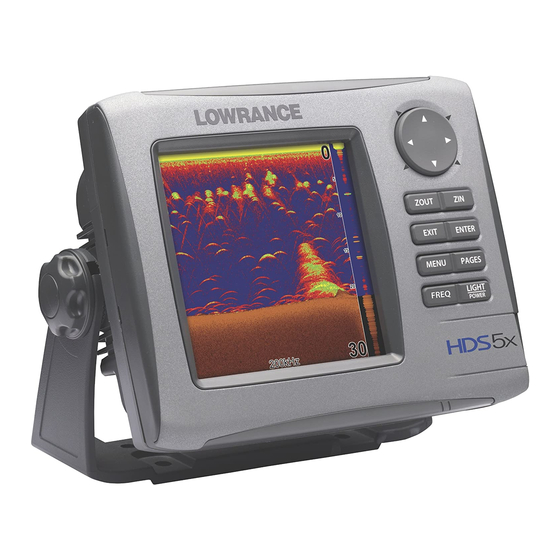
Introduction About this manual Thank you for purchasing from Lowrance, the industry leader in marine technology. This manual documents how to adjust features and options in your display unit. The information in each section follows the same sequence as your display unit’s menus. - Page 6 Introduction Lowrance HDS-5x Sonar ZOUT: Zooms out the screen so you can see more of the water column ZIn: Zooms in the screen, allowing you to get a closer look at desired returns KEYPAD: used to move the cursor, scroll through...
-
Page 7: Getting Started
Getting Started Getting Started Turning on the Unit Press the POWER/LIGHT key to turn on the unit. To turn off the unit, press the POWER/LIGHT key, select Power Off and press enTeR. Setup wizard The Setup wizard will appear when unit is turned on for the first time. -
Page 8: Language
Getting Started Language Selects language used for menus, text boxes and messages. To select a language: 1. Press MenU twice. 2. Select System and press enTeR 3. Highlight Language and press enTeR. 4. Use the keypad to select a language and press enTeR. -
Page 9: Selecting A Fishing Mode
Getting Started Selecting a Fishing Mode Fishing modes enhance the performance of your unit by providing preset packages of sonar settings geared to specific fishing conditions. To select a fishing mode: 1. Press MenU twice. 2. Select Sonar and press enTeR. 3. -
Page 10: Restore Defaults
Getting Started Restore Defaults The Restore Defaults command switches the unit back to the settings it had when you purchased it (default). To Restore Defaults: 1. Press MenU twice. 2. Select System and press enTeR. 3. Highlight Restore Defaults and press enTeR. 4. -
Page 11: Pages Screen
Pages Pages Page icons With Sonar selected, unit will rotate around display a full sonar screen the circular Pages menu Combo display options allows you to display a split screen Sonar icon rotated to center of Page Icons page; has blue border indicating it is the selected page option Pages Screen Consists of page icons that scroll horizontally around the Pages menu. -
Page 12: Data Overlay
Pages Data Overlay Data overlay is information you can display on top of the page screen, allowing you to customize each page with desired data. Data Overlay menu Every page option has its own Data Overlay menu. The menu allows you to edit, add or remove overlay data from the display. -
Page 13: Select Data
Pages Move or Placing a Gauge The Move gauge command allows you to move data overlay to any position on the screen. When you use the Place gauge command, the gauge will be locked in its current position. To move/place a gauge: 1. - Page 14 Pages Digital format Size Analog format Selects the size of the data overlay display. Data overlay can be displayed in four sizes. With the gauge in edit mode (shaded in blue) press the ZOOM OUT key to increase overlay size; press the ZOOM In key to decrease overlay size. Small digital gauge Large analog gauge Limits...
-
Page 15: Configuration Menu
Pages Configuration menu Allows you to Add/Remove sources and adjust Bezel, Caption and Invert Text Settings. Other configuration menu options are covered previously in the section. To access the Configuration menu, highlight Configuration on the Edit Overlay menu and press enTeR. Configuration Settings Adds a bezel to the data overlay gauge, making it easier to Bezel... -
Page 16: Sonar Page
Pages Sonar Page Displays the water column moving from right to left on your unit’s screen. On the right side of the screen, the Amplitude Scope bar previews echoes about to appear on the display. The sonar page supports multiple splitscreen views and 14 color palette settings. Sonar display options are covered in more detail in the Sonar Operation section. -
Page 17: Radar Page (Optional)
Pages Radar Page (optional) Displays the PPI (Position Plan Indicator) screen, Range Rings and the cursor. The PPI can be shifted to show more of a desired portion of the screen (Look Ahead, Center & Offset) and the color palette can be changed to show returns in white, yellow, black or green. - Page 18 Pages Info menu Controls Info page data, page layout and data display format selection. To access the Data menu, press MenU while on the Info page. Dashboards Layout templates that are customized with selected data and saved for on-the-water viewing. You can customize a different layout template for each dashboard or add custom data to the same layout template and save it as a different dashboard each time.
- Page 19 Pages To edit gauge display: 1. Use the keypad to select the gauge you want to edit and press enTeR. The Select Info menu will appear. 2. Use the keypad to select a data category and press enTeR. A list of subcategories will appear.
- Page 20 Pages To add source: 1. Select Add Source from the Edit Info menu and press enTeR. 2. Use the keypad to select the desired category and press enTeR. A list of subcategories will appear. 3. Select the desired subcategory and press enTeR.
-
Page 21: Change Layout
Pages Change Layout Controls the gauge layout of dashboard templates and customized dashboards. That allows you to select a desired gauge layout template for all dashboards. To change layout: 1. Highlight the desired dashboard and press enTeR. 2. Select Change Layout from the Info menu and press enTeR. -
Page 22: Utilities
Pages To remove dashboards: 1. Select the number of the dashboard you want to delete from the numerical dashboard list. 2. Highlight Remove Dashboard and press enTeR. A confirmation message will appear. Numerical 3. Select Delete and press enTeR. dashboard list Settings Opens the Settings menu. -
Page 23: Displaying Combo Pages
Pages Radar selected as combo Sonar/Radar combo page display option Displaying Combo Pages You can display multiple pages at the same time by scrolling the desired page’s icon to the center of the screen and then choosing a secondary page from the list of combo page display options. -
Page 24: Displaying Multiple Panels
Pages Displaying Multiple Panels Multiple panels can be displayed by setting up a combo display using a page that supports the Split feature. By displaying multiple panels, you can view more information on the screen at one time. Step 1: Select sonar split screen Step 2: Choose page from combo display options list To display multiple panels:... - Page 25 Pages Moving panel cursor left/right will change the size of each panel Adjusting panels on combo page Adjusting panels on multi-panel display (Sonar/Info combo shown) (Sonar/Info combo shown) To adjust panel sizes: 1. With the combo page or multi-panel display on the screen, press the PAGeS key.
-
Page 26: Sonar Operation
Sonar Sonar Operation Temperature Graph Surface clutter Water column Range Fish Arches scale Cursor depth Depth Line Brush Water depth, water Colorline Cursor temp and cursor Amplitude Scope coordinates — shows amplitude Blue sonar history bar; reviews of real-time sonar recent sonar history echoes To access the Sonar Page:... -
Page 27: Sonar Menu
Sonar Sonar Menu Accesses features ranging from Auto Sensitivity and Depth Range to Frequency and Stop Sonar. From the Sonar Page, press MenU to access the Sonar Menu. Sonar Menu Sensitivity Controls the level of detail shown on the display. Increasing Sensitivity will show more detail on the screen;... - Page 28 Sonar Wide yellow hard Reddish-blue soft sonar return Colorline sonar returns Distinguishes strong sonar echoes from weak sonar echoes. That makes it easier for you to distinguish fish or structure from the bottom. A hard return will be shown as a wide, bright yellow line, whereas a soft return will be a narrow reddish-blue line.
- Page 29 Sonar Zoom display Bottom Lock Flasher Display • no Split — displays full sonar screen • Zoom — splits display with a zoomed-in panel on the left (press ZOOM key to increase zoom) and a normal sonar view on the right •...
-
Page 30: Sonar Options
Sonar Custom — Upper and Lower Limits Controls not only the depth range (lower limit), but also lets you choose the upper limit. So, instead of a selecting a range that includes the water surface, you can choose upper and lower limits anywhere along the water column. -
Page 31: Palette
Sonar To select a Split option: 1. From the Sonar Options menu, highlight Split and press enTeR. The Split menu will appear. 2. Use the keypad to select the desired option and press enTeR. Palette Sonar display color templates with varying degrees of color and brightness. -
Page 32: Temperature Graph
Sonar Temperature Graph Uses a red line graph with digital display at the top of the screen to illustrate changes in Temperature. The Temperature graph makes it easier to recognize temperature trends. To turn the Temperature Graph on/off, highlight Temperature Graph on the Sonar Options menu and press enTeR. -
Page 33: Measure Distance
Sonar Fish ID Displays fish echoes as fish symbols instead of fish arches with or without depth. This makes it easier to recognize fish on the sonar display. Symbols — places a fish symbol where a fish is detected. Depths — places depths above each fish detected;... - Page 34 Sonar To share/receive sonar data: 1. Press MenU twice, select Sonar and press enTeR. Make sure the units sharing sonar have network sonar turned on. 2. Press exIT twice. 3. Access the Sonar page, on the unit that will be sharing its sonar (master).
-
Page 35: Radar Operation (Optional)
Radar Radar Operation (optional) Range Range Ring Size North Indicator Heading Line Radar orientation indicator Range Rings To access the Radar Page: Press the PAGeS key. Use the keypad to select the Radar Icon and press enTeR. NOTE: You will only be able to see the Radar page if your unit is connected to a radar. -
Page 36: Radar Menu
Radar Radar menu Use the Radar menu to make adjustments to radar display settings and features that not only change the appearance of the display, but also make navigation easier. To access the Radar menu, press the MenU key when the Radar page is on the display. -
Page 37: Auto Gain
Radar Adjust menu options Controls the sensitivity of the radar receiver. Increasing gain will show more detail on the screen; decreasing gain will show Gain less detail. Too much detail will clutter the screen. Conversely, desired returns may not be shown if gain is too low. Reduces or eliminates onscreen clutter Sea Clutter caused by wave action near your vessel. -
Page 38: Sea Clutter
Radar Sea Clutter Allows you to select the Sea Clutter adjustment mode — Auto or Manual. If you make changes to Sea Clutter when it is in auto mode (Harbor or Offshore), Sea Clut- ter will switch to Manual mode. Sea Clutter Options Manual Switches Sea Clutter from Auto to Manual mode... - Page 39 Radar Position Default setting, will position the PPI in the center of Center the screen Shifts the PPI to the bottom of the screen, allowing Look Ahead you to see more of the area in front of your vessel Allows you to move the PPI to a any location on the display.
-
Page 40: Ebl/Vrm Menu
Radar EBL/VRM 1 EBL/VRM 2 EBL/VRM 1 & EBL/ VRM 2 Data Boxes EBL/VRM menu Places selected Electronic Bearing Line and Variable Range Marker on the display. To select an EBL/VRM: 1. Press the MenU key. 2. Use the keypad to select the EBL/VRM and press enTeR. -
Page 41: Guard Zones
Radar Data box Data Box Turns on/off on screen EBL/VRM information box. To turn on/off the EBL/VRM information box, highlight Data box on the EBL/VRM menu and press enTeR. Guard Zones A zone or zones near or around your vessel Guard Zone 2 (sector) that alert you if a radar target enters or leaves a zone. - Page 42 Radar To turn on a Guard Zone: 1. Press MenU, select Guard Zones and press enTeR. Highlight Guard Zone 1 or Guard Zone 2 and press enTeR. To change the shape of Guard Zones 1. Select Shape and press enTeR. 2.
-
Page 43: Settings Menu
Settings Settings Menu The Settings Menu provides access to installation and advanced configuration settings for your unit. To access the Settings menu, press MenU twice. Settings Menu Options System Fuel Vessels Page Alarms Simulator Sonar Units Radar (if applicable) Network System Used to change system settings like units, language and key beeps. - Page 44 Settings To change Text Size: 1. Highlight Text Size from the System menu and press enTeR. 2. Use the keypad to select the desired text size and press enTeR. Key Beeps By default, a tone (key beep) will sound when any key is pushed on the unit.
-
Page 45: Screen Capture
Settings Screen Capture Saves images of your unit’s screen to your unit. You will only be able to review images on your unit. You can not save them to an MMC/SD card. To take a screen capture: 1. Select Screen Capture from the System menu and press enTeR. 2. - Page 46 Settings To access Advanced Settings: 1. Select Advanced on the Settings menu and press enTeR. 2. Highlight a desired setting and use the right/left arrow keys to open (—) or close (+) the setting. To adjust cursor settings: 1. Highlight the desired cursor setting and press enTeR. A dialog box will appear.
-
Page 47: Sonar Settings
Settings Sonar Settings The Sonar Settings Menu is used to modify Sonar options and display settings like Sonar Source, Noise Rejection and Fishing Mode. To access the Sonar Settings: 1. Press MenU twice. 2. Select Sonar and press enTeR. Sonar Settings Menu network Sonar Allows your unit to send/receive sonar data from another sonar unit on an ethernet network. -
Page 48: Manual Mode
Settings To adjust Surface Clarity: 1. Select Surface Clarity from the Sonar Settings menu and press enTeR. 2. Use the keypad to choose the desired option. Scroll Speed Controls how fast the sonar chart scrolls across the screen. A slower scroll speed is best suited for ice fishing or fishing while at anchor. -
Page 49: Fishing Modes
Settings Fishing Modes Enhances the performance of your unit by providing preset packages of sonar settings geared to specific fishing conditions. Settings optimized for fishing modes include: Color Palette, Sensitivity, Interference Rejection, Surface Clarity and Ping Speed, among others. Fishing modes allow you to spend more time fishing and less time adjusting settings. -
Page 50: Installation Menu
Settings To select a Fishing Mode: 1. Select Fishing Mode from the Sonar Settings menu and press enTeR. 2. Use the keypad to select the desired mode and press enTeR. Reset Fishing Mode Resets selected fishing mode to default settings. That is useful when you want to clear settings adjustments made while using a fishing mode. -
Page 51: Water Speed Calibration
Settings Before setting keel offset, measure the distance from the transducer to the lowest part of the keel. If, for example, the keel is 3.5 feet below the transducer, it will be input as –3.5 feet. NOTE: To input a keel offset that accounts for the distance from the transducer to the water surface, you will enter a posi- tive number. -
Page 52: Water Speed Averaging
Settings Water Speed Averaging Averages water speed by measuring your speed at a selected interval. Water speed intervals range from one to 30 seconds. If you select five seconds, your water speed will be recorded every five seconds, then averaged. To select a Water Averaging interval : 1. -
Page 53: Transducer Type
Settings To select a Temperature Averaging interval: 1. Highlight the Temperature Averaging box on the Installation menu. 2. Press the keypad left/right to select the desired interval and press enTeR. Transducer Type Selects the transducer model connected to your display unit. In some transducers with built-in temperature sensors, the temperature may not be accurate if the correct transducer is not selected from the Transducer Type menu. -
Page 54: Radar Settings Menu (Optional)
Settings Radar Settings Menu (optional) Controls Radar options and display settings like Target Expansion, Orientation and Bearings. To access the Radar settings menu: 1. Press MenU twice. 2. Select Radar and press enTeR. Radar Settings Target Expansion Increases the size of radar targets, making them easier to see on the radar display. To turn on/off Target Expansion, highlight Target Expansion and press enTeR. -
Page 55: North Indicator
Settings Black Color Palette White Color Palette Orientation Controls the way the map moves in relation to the movement of your vessel. That allows you to select a desired method for viewing your surroundings on the radar display. • Course Up — map stays at same orientation as the initial bearing to the selected waypoint. -
Page 56: Range Rings
Settings Range Rings Allows you to quickly estimate the distance from your vessel to a another radar target. To turn on/off Range Rings, highlight Range Rings on the Radar Settings menu and press enTeR. Range rings Range markers Range Markers Located below each Range Ring, Range Markers display the distance from your position to each range ring. - Page 57 Settings To set T/M or R: 1. Press MenU twice. 2. Select Radar and press enTeR. 3. Highlight Bearings and press enTeR. 4. Use the arrows to select a bearing and press enTeR. MARPA MARPA automatically tracks selected radar targets, making it easier to avoid collisions.
- Page 58 Settings To adjust CPA and TCPA settings: 1. Press MenU twice 2. Select Vessels and press enTeR. 3. Select Dangerous Vessels and press enTeR. 4. Select the CPA or TCPA text box and press enTeR. 5. Follow the onscreen instructions and press enTeR. 6.
- Page 59 Settings To cancel individual targets: 1. Press the keypad to activate the cursor. 2. Move the cursor over a target you are tracking and press MenU. 3. Select Cancel Target and press enTeR. Cancel individual targets Cancel all targets To cancel all targets: 1.
- Page 60 Settings Target Alarms You can be alerted when a MARPA target breaches CPA or TCPA thresholds by setting an alarm. To set MARPA target alarm: 1. Press MenU twice. 2. Select Alarms and press enTeR. 3. Select Settings and press enTeR.
-
Page 61: Bearing Alignment
Settings Installation Adjustment Menu The installation adjustment menu is used to make adjustments to bearing alignment, range offset, antenna height and open array park angle. When the installation adjustment menu is accessed, press the keypad up/down to select a feature. Press the keypad left/ right to make adjustments to a selected feature. - Page 62 Settings To Adjust Bearing Alignment: 1. Line up the bow of your vessel with a stationary target (lighthouse, pier, etc) at least 1 nm away 2. Select Adjust Bearing Alignment from the Radar Installation menu and press enTeR. The Installation Adjustment menu will appear. 3.
-
Page 63: Antenna Height
Settings Antenna Height Antenna height is the distance from the waterline to the Antenna (scanner). It is important to correctly input antenna height to prevent problems with the Sea Clutter feature. To Adjust Antenna Height: 1. Select Adjust Antenna Height from the Installation menu and press enTeR. - Page 64 Settings Sidelobe suppression (BR24 only) Sidelobes are false returns caused by the reflection of your radar signal. Sidelobe suppression helps reduce the impact of sidelobes on your radar display. The default Auto mode will work well under most conditions. Manually adjusting Sidelobe suppression: 1.
-
Page 65: Fuel
Settings Fuel Used to input fuel data like engine/tank configuration, fuel tank capacity and engine calibration. Your unit uses that data to calculate the overall fuel performance of your vessel. To access the Fuel menu, select Fuel from the Settings menu and press enTeR. Fuel menu Refuel Controls engine calibration and is used to input the amount of fuel added to the... - Page 66 Settings To set tank to full: 1. Highlight the Set to full checkbox on the Refuel screen and press enTeR. 2. Highlight OK and press enTeR. The calibration options screen will appear. You are Tank set to full ready to calibrate. To calibrate engine(s): 1.
-
Page 67: Fuel Used
Settings Fuel Used Data information screen that displays fuel consumption data including fuel used since last fill up, fuel used on the current trip and fuel used during a season. To access fuel used information, select Fuel Used from the Fuel menu and press enTeR. - Page 68 Settings Engine/Tank Configuration Used to input the number of engines and fuel tanks on your vessel. Your unit must have that information to be able to calibrate you engine(s). To select engine-tank configuration: 1. Highlight the vessel configuration drop-down menu and press enTeR. 2.
-
Page 69: Alarms
Settings Alarms This unit has alarms covering everything from depth and water temp rate to fuel and waypoint radius. The alarms list has three tabs: Active, History and Settings. • Active — used to view alarms that have been enabled •... -
Page 70: Units
Settings To silence an alarm: When an Alarm is triggered, a tone will sound and a alarm window will appear on the screen. Press enTeR to silence the alarm and close the alarm window. After alarm is silenced its corresponding alarm bell will continue to flash in the bottom left corner of the screen. -
Page 71: Network
Settings Network Controls network configuration, data sources, serial port settings, waypoint sharing and allows you to monitor network performance (NMEA 2000 and ethernet) and network devices. To access the Network menu, select Network from the Settings menu and press enTeR. Network menu Auto Configure Resets all Data Sources to default settings... - Page 72 Settings Data Source menu Allows you to change the name and scope of a source and add/ remove sources from a NMEA 2000 or ethernet network. To access a Data Source menu, highlight a desired source and press MenU. Rename Used to rename a Data Source.
-
Page 73: Device List
Settings To select a scope: 1. Highlight Scope on the selected device’s data source menu and press enTeR. 2. Use the keypad to select Global or Local and press enTeR. Reset Global and Reset Local Selecting Reset Global will reset all the source selections to default settings and removes all instances on all networked HDS units. -
Page 74: Configuring Devices
Settings Device Menu Options Details Accesses the Device Information screen Refresh Refreshes the device list Sort Allows you to sort device list by Model ID or Serial No. Configuring Devices Devices have different configuration options. Name, tank size and location can be configured on some devices;... -
Page 75: Calibrating Devices
Settings To configure device location: 1. Select a device from the device list and press enTeR. The Device Information screen will appear. 2. Highlight the Configure button and press enTeR. The Device Configuration screen will appear. 3. Highlight the Location dropdown menu and press enTeR. 4. -
Page 76: Nmea 2000 Receive/Send Waypoint
Settings Diagnostics screen: NMEA 2000 Diagnostics screen: UDB Diagnostics Displays diagnostic information on NMEA 2000 networks displays the status of information shared between units (UDB). From the UDB tab, you also can select a unit to be used as the master (primary) unit when sharing information. To access the Diagnostics screen, select Diagnostics from the Network menu and press enTeR. -
Page 77: Vessels (Only Available If Connected To Ais Receiver)
NMEA 0183 Output sentences press exIT. screen NOTE: There is no graphical display of dangerous vessels on the HDS-5x. You can view the numerical position and bearing of dangerous vessels from the Vessels menu. Vessels ( only available if connected to AIS receiver Controls settings used to monitor vessels transmitting AIS information in your area. -
Page 78: Simulator
Settings Dangerous Vessels Allows you to set the dangerous vessel threshold via CPA (Closest point of approach) and TCPA (Time to closest point of approach) settings. To adjust CPA or TCPA settings: 1. Select Dangerous Vessels from the Vessels menu and press enTeR. -
Page 79: Specifications: Hds-5X
Standards compliance: • Waterproofing: IPX7 • EMC: IC RSS-310; FCC Part 15 Class B; IEC60945 Compliance: The Lowrance HDS complies with the follow- ing regulations: • CE compliant under R&TTE directive. • C - Tick compliant under Radiocommunica- tions act 1992. -
Page 80: Unit Care
This can prevent sufficient power from flowing to the unit. Clean the connections to be sure. Sometimes the substance is clear and not easily seen. Contact & Service Information For spare parts or service information, please contact one of our local sales offices or visit our website: www.lowrance.com... -
Page 81: Troubleshooting
Troubleshooting Troubleshooting If your unit is not working, or if you need technical help, use the following troubleshooting section before contacting the customer service department. Unit won’t turn on Check the power cable’s connection at the unit. Make sure the power cable is wired properly. The red wire connects to the positive battery terminal, black to negative or ground. - Page 82 Troubleshooting bubbles. (See the Installation Section for how to install the transducer.) When attaching a transducer to the inside of a hull, ONLY use epoxy available from LEI (see inside back cover for or- der information). Do NOT use RTV silicone rubber adhesive or any other type of epoxy.
- Page 83 Troubleshooting transducer cables away from other electrical wiring on the boat. When trolling over weed beds in 20ft of water or less, you may experience vertical bars, loss of the chart picture, or the digital depth. First, do a soft reset of the unit. Then go to the Full Sonar Chart screen.
- Page 84 Troubleshooting to 60ft or whatever depth you expect the fish to appear at. This will maximize the screen resolution to show small ob- jects larger on the screen. It is unlikely you will see average- sized fish display as arches in a 100ft deep water column. The boat must be moving at a slow trolling speed to see fish arches.
- Page 85 Sometimes resetting your unit can solve unusual issues. Go to Lowrance. com to access a list of reset procedures for Lowrance products. Locate the one that applies to the model you own. Try a Soft Reset first, this will return your settings to factory defaults.
- Page 86 RADAR or the GPS unit is defective. Verify that the Com Port is set properly, if it is then the Lowrance unit will need to be sent in for repair. d. If the TX is blinking but the RX is not then you are not getting any information from the RIM, the processor or the Radar.
-
Page 87: Index
Index Index Add/Removing source 18 Change layout 19 Acquire targets 36 Configure limits 18 Active panel 21 Editing 16 Add dashboard 19 Data overlay Adjusting text size 41 Add/Remove source 13 Adjust panel sizes 22 Editing 10 Advanced settings 43 Move/Place 11 Alarm Limits 67 Select data 11... - Page 88 Index Global source 69 Guard zone configuration 40 Page settings 44 Guard zones 39 Pages screen 9 Ping Speed 28 Info page 15 Radar adjust menu 34 Radar compass overlay 53 Keel offset 48 Radar installation adust menu 57 Key beeps 42 Radar installation menu 57 Keypad 5 Radar interference rejection 35...
- Page 89 Index Sharing sonar 31 Target boost 35 Sidelobe suppression 61 Target expansion 51 Silencing alarms 67 Target trails 51 Simulator 75 Temperature Graph 30 Simulator advanced settings 75 Text size 41 Simulator demo mode 75 Time 42 SIRIUS radio 44 Transducer type 50 Sonar Adjust menu 27 Sonar installation menu 48...
- Page 91 Visit our website: www.lowrance.com © Copyright 2011 *988-10040-001* All Rights Reserved Navico Holding AS...
Need help?
Do you have a question about the HDS-5x and is the answer not in the manual?
Questions and answers
how do i load longitude / latitude locations into my hsd5
To load longitude and latitude locations into your Lowrance HDS-5x, save a known location as a waypoint while at that location. Then, use the unit’s waypoint and navigation functions to manage and return to those saved coordinates.
This answer is automatically generated
how do i load a gps location into the hds5
The Lowrance HDS-5x is a fish finder only and does not have GPS capability. It cannot load or display GPS locations. However, if connected via an Ethernet cable to a GPS-enabled unit like the Lowrance HDS-5m, waypoints may be shared between the devices.
This answer is automatically generated