Table of Contents
Advertisement
Quick Links
Advertisement
Table of Contents

Related Manuals for Gefen EXT-USB2.0-LR


Summary of Contents for Gefen EXT-USB2.0-LR
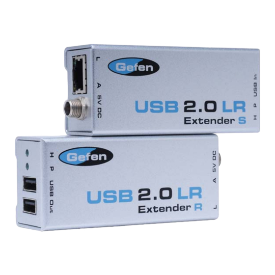
- Page 1 USB 2.0 LR Extender EXT-USB2.0-LR User Manual www.gefen.com...
- Page 2 Notice Gefen Inc. reserves the right to make changes in the hard ware, packaging and any accompanying doc u men ta tion without prior written notice. USB 2.0 LR Extender is a trademark of Gefen Inc. © 2008 Gefen Inc., All Rights Reserved...
-
Page 3: Table Of Contents
CONTENTS Introduction Operation Notes Features Sender Panel Layout Sender Panel Descriptions Receiver Panel Layout Receiver Panel Descriptions Connecting And Operating The USB 2.0 LR Extender Troubleshooting 10 Network Cable Wiring Diagram 11 Wiring Diagram 12 Specifi cations 13 Warranty... -
Page 4: Introduction
USB standards. How It Works Gefen’s USB 2.0 LR supports all major operating systems -- Windows, MacOS and Linux. No software drivers are required. When using in-wall building wiring, stranded patch cables may be used to connect the Sender and Receiver to CAT5 wall plates. -
Page 5: Operation Notes
OPERATION NOTES READ THESE NOTES BEFORE INSTALLING OR OPERATING THE USB 2.0 LR EXTENDER • Use industry standard CAT-5, CAT-5e or CAT-6. Gefen recommends using solid core cabling for maximum performance. • The USB 2.0 LR Extender is USB 2.0/1.1 compliant •... -
Page 6: Features
Receiver supports up to 2 USB powered connections at 500 mA each • Specifi cations: Package Includes (1) Gefen USB 2.0 Extender over CAT5 LR Sender (1) Gefen USB 2.0 Extender over CAT5 LR Receiver (1) 5V DC Power Supply (1) 6 ft. USB Cable... -
Page 7: Sender Panel Layout
SENDER PANEL LAYOUT Front Panel Front Panel Back Panel... -
Page 8: Sender Panel Descriptions
SENDER PANEL DESCRIPTIONS Host Connection LED Indicator This LED will become active once a valid connection is made by the host source and the USB 2.0 LR Extender. Power LED Indicator This LED will become active once a valid connection is made between the included 5V DC power supply and an open wall power socket. -
Page 9: Receiver Panel Layout
RECEIVER PANEL LAYOUT Front Panel Front Panel Back Panel... -
Page 10: Receiver Panel Descriptions
RECEIVER PANEL DESCRIPTIONS Host Connection LED Indicator This LED will become active once a valid connection is made by the host source and the USB 2.0 LR Extender. Power LED Indicator This LED will become active once a valid connection is made between the included 5V DC power supply and an open wall power socket. -
Page 11: Connecting And Operating The Usb 2.0 Lr Extender
CONNECTING AND OPERATING THE USB 2.0 LR EXTENDER How to Connect the USB 2.0 LR Extender Connect the USB source to the USB 2.0 LR Extender sender unit using the supplied USB A to B cable. Connect up to two USB peripherals to the USB 2.0 LR Extender receiver using user supplied USB cables. -
Page 12: Troubleshooting
TROUBLESHOOTING Using the Led Indicators to Troubleshot Issues Power LED The power LED indicators should be active once the included 5V DC power supply has been properly connected between the sending/receiving unit and an open wall power socket. A non-active LED can indicate a power problem. Please check that the power cable is properly connected and locked to the sender/receiver unit. -
Page 13: Network Cable Wiring Diagram
Gefen has specifi cally engineered their products to work with the TIA/EIA-568-B specifi cation. Please adhere to the table below when fi eld terminating cable for use with Gefen products. Failure to do so may produce unexpected results and reduced performance. -
Page 14: Wiring Diagram
WIRING DIAGRAM... -
Page 15: Specifi Cations
SPECIFICATIONS USB 2.0 Speed ..................480 Mbps Link Connectors ................RJ-45 Shielded USB Connectors Transmitter: ............(1) USB type B USB Connectors Receiver: ............. (2) USB type A Dimensions Transmitter: ........... 1.7” W x 1.0” H x 3.4” D Dimensions Receiver: ............4.3” W x 1.1” H x 2.7” D USB .......... -
Page 16: Warranty
Gefen warrants the equipment it manufactures to be free from defects in material and workmanship. If equipment fails because of such defects and Gefen is notifi ed within two (2) years from the date of shipment, Gefen will, at its option, repair or replace the equipment, provided that the equipment has not been subjected to mechanical, electrical, or other abuse or modifi... - Page 17 Rev X1 20600 Nordhoff St., Chatsworth CA 91311 1-800-545-6900 818-772-9100 fax: 818-772-9120 www.gefen.com support@gefen.com...
Need help?
Do you have a question about the EXT-USB2.0-LR and is the answer not in the manual?
Questions and answers