
Related Manuals for Gefen EXT-UHDV-KA-LANS-TX


Summary of Contents for Gefen EXT-UHDV-KA-LANS-TX
- Page 1 *Preferred 60Hz, 4:2:0 Multi-Format HDMI & VGA KVM over IP EXT-UHDV-KA-LANS-TX EXT-UHDV-KA-LANS-RX User Manual Release A2...
- Page 2 Important Safety Instructions Read these instructions. Keep these instructions. Heed all warnings. Follow all instructions. Do not use this product near water. Clean only with a dry cloth. Do not block any ventilation openings. Install in accordance with the manufacturer’s instructions.
- Page 3 Gefen/Core Brands, LLC warrants the equipment it manufactures to be free from defects in material and workmanship. If equipment fails because of such defects and Gefen LLC is notified within the specified warranty period* from the documented** date of purchase, Gefen will, at its option, repair or replace the equipment, provided that the equipment has not been subjected to mechanical, electrical, or other abuse or modifications.
-
Page 4: Technical Support
Contacting Gefen Technical Support Technical Support (707) 283-5900 (800) 472-5555 8:00 AM to 5:00 PM Monday - Friday, Pacific Time Email support@gefen.com http://www.gefen.com Mailing Address Gefen Core Brands, LLC c/o Customer Service 1800 S McDowell Blvd Petaluma, CA 94954 USA... - Page 5 • Gefen highly recommends the use of the Syner-G software and Matrix Controller (Gefen part no. EXT-CU-LAN) for setting up and controlling the operation of a Video-over-IP network using these products. • Shielded CAT-5e (or better) cables should not exceed 330 feet (100 meters) between the Sender / Receiver unit and the network.
- Page 6 High-speed isochronous devices, such as webcams are NOT supported © 2017 Gefen, LLC. All Rights Reserved. All trademarks are the property of their respective owners. Gefen, LLC reserves the right to make changes in the hardware, packaging, and any accompanying documentation without prior written notice.
- Page 7 Licensing This product uses software that is subject to open source licenses, including one or more of the General Public License Version 2 and Version 2.1, Lesser General Public License Version 2.1 and Version 3, BSD, and BSD-style licenses. Distribution and use of this product is subject to the license terms and limitations of liability provided in those licenses.
- Page 8 Supports up to 7.1 channels of HBR (High Bit Rate) digital audio including Dolby Atmos®, Dolby® TrueHD, DTS:X™, and DTS-HD Master Audio™ • When used with Gefen DVI-to-HDMI cables (not included), supports the use of DVI sources and DVI displays up to 1080p Full HD and 1920x1200 (WUXGA) •...
-
Page 9: Packing List
The 4K Ultra HD HDMI & VGA KVM over IP ships with the items listed below. The packing contents of the Sender and Receiver unit are listed below. If any of these items are not present in the box when you first open it, immediately contact your dealer or Gefen. EXT-UHDV-KA-LANS-TX •... -
Page 10: Table Of Contents
Configuring Unicast Mode ................25 Switching between Sender units in Unicast mode ........27 Configuring Multicast Mode ................. 30 Discovery Mode....................32 Gefen Syner-G Discovery ................32 Finding Your Device ..................33 Using RS-232 ...................... 35 RS-232 under Unicast Mode ............... 38 RS-232 under Multicast Mode .............. - Page 11 Table of Contents Advanced Operation Telnet Access ...................... 60 Commands ......................61 Discovery Service ..................61 Help ......................61 Network ....................... 61 Routing ......................62 RX Specific ....................63 Serial ......................64 System ......................64 TX Specific ....................64 USB ......................65 Video ......................
- Page 12 This page left intentionally blank.
-
Page 13: Getting Started
60Hz, 4:2:0 Multi-Format HDMI & VGA KVM over IP Getting Started... -
Page 14: Introduction
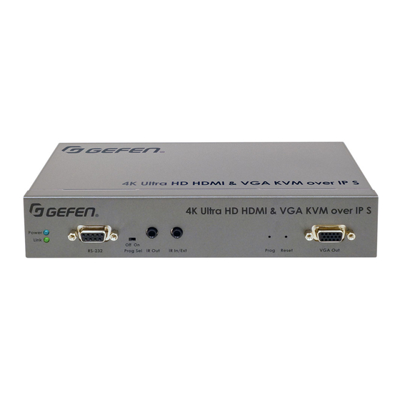
Prog Sel For factory use only. This switch must stay in the Off position. IR Out Connect an IR Emitter cable (Gefen part no. EXT-IREMIT) from this port to the UHD/HD source to control the source from the viewing location. - Page 15 ® monitor either the HDMI or VGA input signal. Power Link RS-232 Prog Sel IR Out IR In/Ext Prog Reset VGA Out EXT-UHDV-KA-LANS-TX 5V DC LAN (PoE) VGA In HDMI In Line In Line Out Name Description Power Connect the included 5V DC locking power supply to this power receptacle.
-
Page 16: Receiver Unit
Introduction Receiver Unit HDMI Power On Off Link USB2.0 USB1.1 Reset IR In/Ext IR Out Prog Sel RS-232 Name Description EXT-UHDV-KA-LANS-RX Power This LED glows solid blue when the unit is connected to an AC outlet and the unit is Line In Line Out Opt Out HDMI Out VGA Out... - Page 17 IR output. IR Out Connect an IR Emitter cable (Gefen part no. EXT-IREMIT) from this port to the UHD/HD source to control the source from the viewing location.
- Page 18 Introduction HDMI Power On Off Link USB2.0 USB1.1 Reset IR In/Ext IR Out Prog Sel RS-232 EXT-UHDV-KA-LANS-RX Line In Line Out Opt Out HDMI Out VGA Out Prog 3 (POE) 5V DC Name Description VGA Out Connect a VGA cable from this port to a VGA display.
-
Page 19: Installation & Configuration
Prog Sel IR Out IR In/Ext Prog Reset VGA Out If NOT USING A PoE-compliant switch, then connect the included 5V DC power supplies to the Sender and Receiver unit. EXT-UHDV-KA-LANS-TX 5V DC LAN (PoE) VGA In HDMI In Line In Line Out... - Page 20 Receiver unit Connect to LAN / DHCP server Launch the Gefen Syner-G app to discover the IP address of the Sender/Receiver unit. See the Gefen Syner-G User Manual for more information. 10. Click the desired unit from the list. The currently selected unit will be highlighted in red.
- Page 21 Installation & Configuration Once all IP settings have been adjusted, click the Apply button. 10. Click the Reboot button to apply changes. 11. Repeat steps 7 - 10 for each Sender and Receiver unit as necessary. Information The IP address of both the Sender and Receiver unit can be viewed by disconnecting the HDMI cable from the Sender unit (of from the source device), as shown in the example below.
- Page 22 Installation & Configuration 13. The Login screen will be displayed. 14. In order to change network settings, you must login as “Administrator”. Select the “Administrator” username from the drop-down list. 15. Type the password in the Password field. The default password for “Administrator” is admin.
- Page 23 Installation & Configuration 18. Click the desired IP Mode button. • If Static mode is selected, then enter the IP Address, Subnet Mask, and Default Gateway. Contact your system administrator if necessary. • If DHCP mode is selected, then the IP address, subnet mask, and default gateway will be specified by the DHCP server.
-
Page 24: Using A Direct Connection
Receiver can be used, we recommend using LAN 3 (PoE) for the sake of consistency. Connect another shielded CAT-5e (or better) cable from one of the LAN ports on the Receiver unit to a PC. EXT-UHDV-KA-LANS-TX HDMI Power On Off... - Page 25 Installation & Configuration Local IP = Receiver unit FW: V1.53H-Oct-24 779c Local IP: 169.254.7.231 Remote IP: 169.254.6.250 Waiting for video source - standby ID: 001C9103C003 Remote IP = Sender unit Make note of both IP addresses. These IP addresses can be entered in a Web browser to access the built-in Web interface.
-
Page 26: Supplementary Connections
2.2 and USB 1.1 ports are supplied. ► Connect an IR Emitter (Gefen part no. EXT-IREMIT) to the Sender unit and attach it to the IR sensor on the device to be controlled. Connect an IR Extender (Gefen part no. EXT-RMT-EXTIRN) to the Receiver unit if the IR sensor will not be within line-of-site for proper IR control. -
Page 27: Sample Wiring Diagram
Installation & Configuration Sample Wiring Diagram CAT-5 (or better) (Up to 330 ft) HDMI USB 1.1 RS-232 Controlled Powered Speakers or Device Headphones USB 2.0 to other LAN devices Gigabit Switch AV Receiver ANALOG AUDIO TOSLINK RS-232 IR Emitter 4K Blu-ray Player USB Drive IR Emitter... - Page 28 This page left intentionally blank.
-
Page 29: Basic Operation
60Hz, 4:2:0 Multi-Format HDMI & VGA KVM over IP Basic Operation page | 17... -
Page 30: Led Status
LED Status The Power and Link LED indicators on the Sender and Receiver unit provides basic information on the current status of the 4K Ultra HD HDBaseT Extender w/ 2-way IR and POL. The information, in the tables below, applies to both the Sender and Receiver unit. Link Status Description... -
Page 31: Setting The Video Channel
Setting the Video Channel In order for a Sender and Receiver unit to communicate with one another, they must both be set to the same video channel. This is similar to changing the channel on a set-top box in order to view a different program. Pressing and releasing either the CH + or CH - buttons on the front of the Receiver unit can also be used to change the video channel. -
Page 32: Setting The Channel Using The Front Panel
Setting the Video Channel Setting the Channel using the Front Panel Press the - or +/USB button to display the current channel number. Channel numbers range from 0 to 39900. HDMI Power On Off Link USB2.0 USB1.1 Reset IR In/Ext IR Out Prog Sel RS-232... - Page 33 Setting the Video Channel Once the current channel is displayed, do one of the following: • Press the - button to decrement the current channel number. • Press the +/USB button to increment the current channel number. To set the video channel on a Sender unit, use the Web interface. See Setting the Channel using the Web Interface (page 19) for more information.
- Page 34 Setting the Video Channel The Receiver unit, on channel 5, is now receiving the signal from the Sender unit on channel 5. Receiver unit Sender unit Sender unit Sender unit page | 22...
-
Page 35: Blocking & Masking Video
Blocking & Masking Video Use the Block Video option on a Sender unit to prevent video from being transmitted to each of the connected Receiver units (multicast mode only). Use the Mask Video option to selectively block video on the desired Receiver units. ►... - Page 36 Blocking & Masking Video ► Block Video Information The Block Video option is only applicable in multicast mode. Access the Web interface of a Sender unit by entering the IP address in the address bar of the browser. Login as “Administrator”. Click the Functions tab.
-
Page 37: Unicast & Multicast Modes
Unicast & Multicast Modes Configuring Unicast Mode The term unicast is used to describe a configuration where information is sent from one point to another point. It is possible to have multiple Sender and Receiver units connected in a system. However, in unicast mode a Sender unit can communicate with only one Receiver unit at a time. - Page 38 Unicast & Multicast Modes Click the Network tab. Click the Unicast button under the Network Mode window group. When selected, the Unicast button will be highlighted in blue. Click the Apply button in the lower-right corner of the Network Mode group. The following message will be displayed, at the top of the page, indicating that the casting mode has been applied to the Sender or Receiver unit.
-
Page 39: Switching Between Sender Units In Unicast Mode
Unicast & Multicast Modes Switching between Sender units in Unicast mode When multiple Sender and Receiver unit are used in unicast mode, the 4K Ultra HD HDMI & VGA KVM over IP behaves as a switcher. In unicast mode, a Sender unit can communicate with only one Receiver unit at a time. - Page 40 Unicast & Multicast Modes Figure 2.3 - Unicast mode: Receiver unit R1 is now connected to Sender unit S1. Receiver unit Sender unit Receiver unit Sender unit Sender unit Now, observe the result when both Sender S1 and S2 are set to channel 5: Figure 2.4 - Unicast mode violation: Two Sender units (S1 and S2) using the same video channel.
- Page 41 Unicast & Multicast Modes When using unicast mode, each of the Sender units must be assigned a unique channel and should never be changed. Use the Receiver unit to switch (channels) between Sender units. Information In unicast mode, if an additional Sender unit is introduced into a system with the same channel as another Sender unit, then the Receiver unit will continue to receive audio/video data from the Sender unit which was connected first.
-
Page 42: Configuring Multicast Mode
Unicast & Multicast Modes Configuring Multicast Mode The term multicast is used to describe a configuration where information is sent from one or more points to a set of other points. For example, a single Sender unit can transmit data to multiple Receiver units. - Page 43 Unicast & Multicast Modes Click the Network tab. Click the Multicast button under the Network Mode window group. When selected, the Multicast button will be highlighted in blue. Click the Apply button in the lower-right corner of the Network Mode group. The following message will be displayed, at the top of the page, indicating that the casting mode has been applied to the Sender or Receiver unit.
-
Page 44: Discovery Mode
Click the Network tab. Under the IP Setup window group, check the Gefen Syner-G Discovery box to allow the Gefen Syner-G software to locate the unit. If you do not want the unit to be discoverable, then un-check this box. -
Page 45: Finding Your Device
Under the IP Setup window group, click the Show Me button. By default, the Hide Me button will be selected. Although shown, below, it is not necessary to have the Gefen Syner-G Discovery option enabled in order to use the Find Your Device feature. - Page 46 Discovery Mode The following message will be displayed, at the top of the page, indicating that the LED indicators on the unit are blinking. The Power and Link LED indicators will continue to blink until the Hide Me button is clicked.
-
Page 47: Using Rs-232
Using RS-232 The 4K Ultra HD HDMI & VGA KVM over IP supports RS-232 pass-through, allowing the control of remote RS-232 devices. The Sender and Receiver unit which are being used to pass-through the RS-232 data must be set to the same baud rate as the RS-232 host and client. - Page 48 Using RS-232 Access the Web interface for the Sender unit and login as “Administrator”. Click the Functions tab. Locate the Serial over IP group and change the RS-232 settings to match the settings of the RS-232 device that is being used. In this case, we need to use the settings from Table 2.1 (see previous page).
- Page 49 Using RS-232 The following message will be displayed, at the top of the page, indicating that the new Serial over IP options have been applied. Click the Reboot button at the bottom of the page. If the Reboot button is not clicked, the following message will be displayed, indicating that the unit must be rebooted.
-
Page 50: Rs-232 Under Unicast Mode
Using RS-232 RS-232 under Unicast Mode In unicast mode, a Sender unit will be able to communicate with only one Receiver unit at a time. Figure 2.7 - In unicast mode, the host can talk to only one RS-232 device at a time. Receiver unit RS-232 device Automation... -
Page 51: Usb Control
USB Control USB under Unicast Mode When connecting USB devices to the 4K Ultra HD HDMI & VGA KVM over IP, the functionality is similar to that of video and RS-232. Information The 4K Ultra HD HDMI & VGA KVM over IP Sender and Receiver units shipped from the factory in unicast mode. - Page 52 USB Control Locate the USB over IP group and make sure the Enable USB over IP box is checked. This is the default setting. Note that in unicast mode, the Operation Mode is automatically set to Active on link and cannot be changed. Make sure that the USB Mouse Mode is set to High Resolution.
-
Page 53: Usb Under Multicast Mode
USB Control USB under Multicast Mode When connecting USB devices to the 4K Ultra HD HDMI & VGA KVM over IP, the functionality is similar to that of video and RS-232. There are two USB modes available in multicast mode: Active per request mode and Active on link mode. Using the last example, another keyboard and mouse device has been connected to Receiver R1. - Page 54 USB Control Note that in multicast mode, the Operation Mode for both Sender and Receiver units are automatically set to Active per request mode. Under Active per request mode, multiple USB devices may be present on one or more Receiver units. However, only one Receiver unit can have USB control at a time. By default, the first Receiver unit connected to the system will have USB control.
- Page 55 USB Control Figure 2.10 - Receiver unit R2 currently has USB control. Receiver unit Sender unit Receiver unit Sender unit Sender unit USB cable Important If switching between Active per request mode and Active on link mode, the Apply and Reboot buttons must be clicked to apply changes. The next example will consist of switching USB control between two Receiver units.
-
Page 56: Active Per Request Mode
USB Control Active per request mode Press and hold the CH + USB button on the desired Receiver unit, for at least two seconds. The message “Starting USB” will appear on the connected display. Figure 2.11 - Receiver unit R1 has USB control. Receiver unit Sender unit Receiver unit... -
Page 57: Active On Link Mode
USB Control Active on link mode Under Active on link mode, a maximum of four USB devices can be used within a system. In the diagram, on the previous page, the system is already using the maximum number of USB devices (2 USB devices per Receiver). If we had two more Receiver units (making a total of four Receiver units), we would only be able to connect one USB device to each Receiver unit. -
Page 58: Audio Connections
RS-232 Prog Sel IR Out IR In/Ext Prog Reset VGA Out Connect to Line Out on computer Sender unit EXT-UHDV-KA-LANS-TX 5V DC LAN (PoE) VGA In HDMI In Line In Line Out Connect to Line In on computer Connect a 3.5mm mini-stereo cable from the Line In port on the Receiver to the output of a microphone pre-amp or another “Line Level”... - Page 59 Audio Connections Connect the Line Out port to powered speakers or a pair of headphones. Connect a Gefen CAB-TLINK-6MM TOSLINK cable from the Opt Out port to the HDMI Power On Off Optical Digital Input of an AV receiver or amplifier.
-
Page 60: Audio Sources And De-Embedding
Audio Connections Figure 2.13 - The Line In port, on all Receiver units, is automatically disabled in multicast mode. Line-level source Powered speakers Receiver unit Powered speakers Line In Line Out Sender unit Receiver unit Line Out Sender unit HDMI In Sender unit Line Out Line In... -
Page 61: Creating Video Walls
Creating Video Walls The web interface 4K Ultra HD HDMI & VGA KVM over IP allows the creation of video walls up to 16 horizontal and 16 vertical displays. Video walls may contain any number or rows and columns and any combination of these can be enabled, as necesary. Wall Size and Layout Access the Web interface for the Receiver unit. - Page 62 Creating Video Walls Select the row and column positions using the Row Position and Column Position drop-down lists. Click the drop-down list, next to the Apply button, to select the desired host or client to which these settings will be applied. If the All option is selected, then all parameters will be transferred to all Receiver units.
-
Page 63: Bezel And Gap Compensation
Creating Video Walls Bezel and Gap Compensation Display devices have a region where video data is not displayed. This area is called the bezel. Bezel compensation takes this area into account when a single video source is mapped across multiple displays. It is recommended, when a video wall is set up for the first time, that bezel compensation values be set to zero. -
Page 64: Setting The Video Mode
Setting the Video Mode The video mode can be changed using the Mode button or through the Web interface of the Sender unit. Consecutively pressing the Mode button on the Sender unit will switch between Graphic and Video mode. Using the Web interface Access the Web interface for the Sender unit. -
Page 65: Changing The Password
Changing the Password Access the Web interface for the Sender / Receiver unit. Login as “Administrator”. Click the System tab. Under the Password Change window group, enter the new password for the desired username. Note that the new password will not be masked when it is entered. Click the Change button. -
Page 66: Performing A Factory Reset
Performing a Factory Reset The 4K Ultra HD HDMI & VGA KVM over IP can be reset using the Web interface or using the buttons on the front panel. When using the Web interface, the Sender / Receiver units will automatically be reset to Auto IP mode. When using the front-panel buttons, the Sender / Receiver can be reset to either Auto IP or Static IP mode. - Page 67 Performing a Factory Reset Both the Power and Link LED indicators will begin to flash. HDMI Power On Off Link USB2.0 USB1.1 Reset IR In/Ext IR Out Prog Sel RS-232 After both LED indicators stop flashing, the unit will be reset. Repeat the process for each unit.
-
Page 68: Reboot Using The Web Interface
Performing a Factory Reset The 4K Ultra HD HDMI & VGA KVM over IP Sender or Receiver unit can be rebooted in three different ways: Using the Web interface, the Reset button on the front panel, or simply disconnecting and reconnecting the power. Reboot using the Web Interface Access the Web interface for the Sender / Receiver unit. -
Page 69: Reboot Using The Front Panel
HDMI Power On Off Link USB2.0 USB1.1 Reset IR In/Ext IR Out Prog Sel RS-232 EXT-UHDV-KA-LANS-TX Reset button 5V DC LAN (PoE) VGA In HDMI In Line In Line Out EXT-UHDV-KA-LANS-RX Line In Line Out Opt Out HDMI Out VGA Out... - Page 70 This page left intentionally blank.
-
Page 71: Advanced Operation
60Hz, 4:2:0 Multi-Format HDMI & VGA KVM over IP Advanced Operation page | 59... -
Page 72: Telnet Access
Telnet Access Information By default, the Telnet login credentials are disabled. This setting is required when using the Matrix controller (Gefen part no. EXT-CU-LAN) but can be #use_telnet_login enabled for security purposes. Use the command to enable or disable this feature. -
Page 73: Commands
Commands Important Commands that are limited to a Sender or Receiver unit are marked as “Tx only” and “Rx only”, respectively. Unless otherwise noted, commands can be used when connected to either a Sender or Receiver unit. Discovery Service Command Description #get_device_desc Displays the device description... -
Page 74: Routing
Commands Command Description #get_telnet_login Displays the status of the Telnet login #get_telnet_port Displays the Telnet listening port #get_telnet_welcome Displays the Telnet welcome message #get_udp_access Displays the UDP access state #get_udp_port Displays the UDP listening port #get_web_port Displays the HTTP listening port #set_gateway Sets the gateway address #set_ip_address... -
Page 75: Rx Specific
Commands RX Specific Command Description #get_clk_lock Displays the audio clock lock #get_edid_copy Displays the EDID copy state (Rx only) #get_mask Displays the current video mask state #get_rx_id Displays the ID of the Receiver unit #get_vw Displays the status of the video wall #get_vw_bc Displays the video wall bezel compensation #get_vw_delay... -
Page 76: Serial
Commands Serial Command Description #get_serial_allow Displays the Serial-over-IP state #get_serial_baud Displays the serial baud rate setting #get_serial_bits Displays the serial data bits setting #get_serial_parity Displays the serial parity setting #get_serial_stop Displays the serial stop bits setting #set_serial_allow Enables or disables Serial-over-IP mode #set_serial_baud Sets the baud rate for the serial port #set_serial_bits... -
Page 77: Usb
Commands Command Description #get_usb_allow Displays the USB-over-IP state #get_usb_mode Displays the USB operating mode #get_usb_mouse Displays the mouse operating mode #set_usb_allow Enables / disables USB over IP #set_usb_mode Sets the USB operating mode #set_usb_mouse Sets the USB mouse mode Video Command Description #get_video_allow... - Page 78 Commands #help Displays a list of available commands. The commands listed are specific to either the Sender or Receiver unit. Syntax #help Parameters None Example #help #HELP #FACTORY_RESET #FW_UPGRADE #GET_BLOCK #GET_CLK_LOCK #GET_DEVICE_DESC #GET_DISCOVERY #GET_DISCOVERY_MODE #GET_EDID_COPY #GET_FIRMWARE_VERSION #GET_GATEWAY #GET_HDCP #GET_IP_ADDRESS #GET_IP_MODE #GET_IPCONFIG #GET_MASK #GET_NET_MODE...
- Page 79 Commands #factory_reset Resets the unit to factory-default settings. param1 must be included and set to 1. Syntax #factory_reset param1 Parameters param1 Integer Example #factory_reset 1 RESET TO FACTORY DEFAULTS Related Commands #reboot page | 67...
- Page 80 Commands #fw_upgrade Upgrades the firmware from the command. Syntax #fw_upgrade filename Parameters filename String Example #fw_upgrade firmware_file_v2.bin page | 68...
- Page 81 Commands #get_block Displays the current video blocking state. This command is only available when connected to a Sender unit. To enable or disable the video blocking state, refer to the #set_block command. Syntax #get_block Parameters None Example #get_block BLOCK DISABLED Related Commands #get_mask #set_block...
- Page 82 Commands #get_clk_lock Displays the audio clock lock. Syntax #get_clk_lock Parameters None Example #get_clk_lock CLK_LOCK 0 Related Commands #set_clk_lock page | 70...
- Page 83 Commands #get_device_desc Displays the description of the Sender / Receiver unit. Syntax #get_device_desc Parameters None Example #get_device_desc DEVICE DESCRIPTION IS Genius Sender 2 Related Commands #set_device_desc page | 71...
- Page 84 Commands #get_discovery Displays the current discovery mode setting. Syntax #get_discovery Parameters None Example #get_discovery DISCOVERY SERVICE SET TO ENABLED Related Commands #set_discovery #set_showme page | 72...
- Page 85 Commands #get_discovery_mode Displays the current discovery mode setting. Syntax #get_discovery_mode Parameters None Example #get_discovery_mode DISCOVERY MODE 1 Related Commands #set_discovery #set_discovery_mode #set_showme page | 73...
- Page 86 Commands #get_edid_copy Displays the EDID copy state. This command is only available when connected to a Receiver unit. Syntax #get_edid_copy Parameters None Example #get_edid_copy COPY EDID OF CONNECTED DISPLAY IS ENABLED Related Commands #set_edid_copy page | 74...
- Page 87 Commands #get_firmware_version Displays the firmware version. Syntax #get_firmware_version Parameters None Example #get_firmware_version FIRMWARE VERSION IS 1.83hv Related Commands #fw_upgrade page | 75...
- Page 88 Commands #get_gateway Displays the gateway address of the Sender/Receiver unit. Syntax #get_gateway Parameters None Example #get_gateway GATEWAY: 192.168.0.1 Related Commands #get_ip_address #get_ip_mode #get_ipconfig #get_netmask #set_gateway #set_ip_address #set_ip_mode #set_netmask page | 76...
- Page 89 Commands #get_hdcp Displays the current HDCP state. This command is only available when connected to a Sender unit. Syntax #get_hdcp Parameters None Example #get_hdcp HDCP ENCRYPTED SOURCE IS ENABLE Related Commands #set_hdcp_allow page | 77...
- Page 90 Commands #get_ip_address Displays the current IP address of the Sender or Receiver unit. Syntax #get_ip_address Parameters None Example #get_ip_address IP: 10.5.64.60 Related Commands #get_gateway #get_ip_mode #get_ipconfig #get_netmask #get_web_port #set_gateway #set_ip_address #set_ip_mode #set_netmask #set_web_port page | 78...
- Page 91 Commands #get_ip_mode Displays the current IP mode. Syntax #get_ip_mode Parameters None Example #get_ip_mode IP MODE IS SET TO DHCP Related Commands #get_gateway #get_ip_address #get_ipconfig #get_netmask #get_web_port #set_gateway #set_ip_address #set_ip_mode #set_netmask #set_web_port page | 79...
- Page 92 Commands #get_ipconfig Displays the current IP configuration. In addition to providing the MAC address and the broadcast IP address, this command also provides the same information as executing the #get_ip_mode, #get_ip_address, #get_netmask, and #get_gateway commands. Syntax #get_ipconfig Parameters None Example #get_ipconfig IP CONFIGURATION IS : IP MODE: DHCP...
- Page 93 Commands #get_mask Displays the current video mask state. This command is only available when connected to a Receiver unit. To enable or disable video masking on a Receiver unit, refer to the #set_mask command. Syntax #get_mask Parameters None Example #get_mask MASK DISABLED Related Commands #get_block...
- Page 94 Commands #get_net_mode Displays the current network mode setting. Syntax #get_net_mode Parameters None Example #get_net_mode NETWORK MODE SET TO MULTICAST Related Commands #set_net_mode page | 82...
- Page 95 Commands #get_netmask Displays the current net mask setting. Syntax #get_netmask Parameters None Example #get_netmask NETMASK: 255.255.255.0 Related Commands #get_gateway #get_ip_address #get_ipconfig #get_web_port #set_gateway #set_ip_address #set_ip_mode #set_netmask #set_web_port page | 83...
- Page 96 Commands #get_pq_mode Displays the picture quality mode. This command is only available when connected to a Sender unit. Syntax #get_pq_mode Parameters None Example #get_pq_mode TRANSMITTER PICTURE QUALITY IS VIDEO Related Commands #set_pq_mode page | 84...
- Page 97 Commands #get_remote_udp_access Displays the remote UDP access state. Syntax #get_remote_udp_access Parameters None Example #get_remote_udp_access REMOTE UDP ACCESS IS ENABLED Related Commands #get_remote_udp_ip #get_remote_udp_port #get_udp_access #get_udp_port #set_remote_udp_access #set_remote_udp_ip #set_remote_udp_port #set_udp_access #set_udp_port page | 85...
- Page 98 Commands #get_remote_udp_ip Displays the remote UDP IP address. Syntax #get_remote_udp_ip Parameters None Example #get_remote_udp_access REMOTE UDP IP: 192.168.1.29 Related Commands #get_remote_udp_access #get_remote_udp_port #get_udp_access #get_udp_port #set_remote_udp_access #set_remote_udp_ip #set_remote_udp_port #set_udp_access #set_udp_port page | 86...
- Page 99 Commands #get_remote_udp_port Displays the remote UDP listening port. Syntax #get_remote_udp_port Parameters None Example #get_remote_udp_port REMOTE UDP COMMUNICATIONS PORT: 50008 Related Commands #get_remote_udp_access #get_remote_udp_ip #get_udp_access #get_udp_port #set_remote_udp_access #set_remote_udp_ip #set_remote_udp_port #set_udp_access #set_udp_port page | 87...
- Page 100 Commands #get_rx_channel Displays the current channel of the Receiver unit. To set the video channel of a Receiver unit, use the command. Syntax #get_rx_channel Parameters None Example #get_rx_channel RECEIVER CHANNEL: 1 Related Commands #get_tx_channel #set_tx_channel page | 88...
- Page 101 Commands #get_rx_id Displays the ID of the Receiver unit. This command is only available when connected to a Receiver unit. Syntax #get_rx_id Parameters None Example #get_rx_id RX ID: 8 Related Commands #set_rx_id page | 89...
- Page 102 Commands #get_serial_allow Displays the Serial-over-IP state. Use the #set_serial_allow command to enable or disable the Serial-over-IP feature. Syntax #get_serial_allow Parameters None Example #get_serial_allow SERIAL OVER IP is ENABLE Related Commands #get_serial_baud #get_serial_parity #get_serial_stop #set_serial_allow #set_serial_baud #set_serial_bits #set_serial_parity #set_serial_stop page | 90...
- Page 103 Commands #get_serial_baud Displays the serial baud rate setting. Use the #set_serial_baud command to set the baud rate. Syntax #get_serial_baud Parameters None Example #get_serial_baud SERIAL BAUD RATE IS 19200 Related Commands #get_serial_allow #get_serial_bits #get_serial_parity #get_serial_stop #set_serial_allow #set_serial_baud #set_serial_bits #set_serial_parity #set_serial_stop page | 91...
- Page 104 Commands #get_serial_bits Displays the serial data bits setting. Use the #set_serial_bits command to set the number of data bits. Syntax #get_serial_bits Parameters None Example #get_serial_bits SERIAL DATA BITS IS 8 Related Commands #get_serial_allow #get_serial_baud #get_serial_parity #get_serial_stop #set_serial_allow #set_serial_baud #set_serial_bits #set_serial_parity #set_serial_stop page | 92...
- Page 105 Commands #get_serial_parity Displays the serial parity bit setting. Use the #set_serial_parity command to set the parity bit. Syntax #get_serial_parity Parameters None Example #get_serial_parity SERIAL PARITY MODE SET TO NONE Related Commands #get_serial_allow #get_serial_baud #get_serial_bits #get_serial_stop #set_serial_allow #set_serial_baud #set_serial_bits #set_serial_parity #set_serial_stop page | 93...
- Page 106 Commands #get_serial_stop Displays the serial stop bits setting. Use the #set_serial_stop command to set the number of stop bits. Syntax #get_serial_stop Parameters None Example #get_serial_stop SERIAL STOP BITS IS 1 Related Commands #get_serial_allow #get_serial_baud #get_serial_bits #get_serial_parity #set_serial_allow #set_serial_baud #set_serial_bits #set_serial_parity #set_serial_stop page | 94...
- Page 107 Commands #get_showme Displays the showme state. Syntax #get_showme Parameters None Example #get_showme SHOW ME DISABLED Related Commands #set_showme page | 95...
- Page 108 Commands #get_telnet_access Displays the Telnet access state. Use the #set_telnet_access command to enable or disable Telnet access. Syntax #get_telnet_access Parameters None Example #get_telnet_access TELNET ACCESS IS ENABLED Related Commands #get_telnet_login #get_telnet_port #get_telnet_welcome #set_telnet_access #set_telnet_pass #set_telnet_login #set_telnet_pass #set_telnet_port #set_telnet_welcome page | 96...
- Page 109 Commands #get_telnet_login Displays the Telnet login status. Syntax #get_telnet_login Parameters None Example #get_telnet_login TELNET LOGIN SET TO DISABLED Related Commands #get_telnet_access #get_telnet_port #get_telnet_welcome #set_telnet_access #set_telnet_pass #set_telnet_login #set_telnet_pass #set_telnet_port #set_telnet_welcome page | 97...
- Page 110 Commands #get_telnet_port Displays the Telnet listening port. Syntax #get_telnet_port Parameters None Example #get_telnet_port TELNET COMMUNICATION PORT: 23 Related Commands #get_telnet_access #get_telnet_login #get_telnet_welcome #set_telnet_access #set_telnet_pass #set_telnet_login #set_telnet_pass #set_telnet_port #set_telnet_welcome page | 98...
- Page 111 Commands #get_telnet_welcome Displays the Telnet welcome message. Use the #set_telnet_welcome to create a custom welcome message. Syntax #get_telnet_welcome Parameters None Example #get_telnet_welcome TELNET WELCOME SCREEN IS DISABLED Related Commands #get_telnet_access #get_telnet_login #get_telnet_port #set_telnet_access #set_telnet_pass #set_telnet_login #set_telnet_pass #set_telnet_port #set_telnet_welcome page | 99...
- Page 112 Commands #get_tx_channel Displays the video channel of the Sender unit. This command is only available when connected to a Sender unit. Syntax #get_tx_channel Parameters None Example #get_tx_channel TRANSMITTER CHANNEL: 1 Related Commands #get_rx_channel #set_tx_channel page | 100...
- Page 113 Commands #get_udp_access Displays the UDP access state. Use the #set_udp_access command to enable or disable UDP access. Syntax #get_udp_access Parameters None Example #get_udp_access UDP ACCESS IS ENABLED Related Commands #get_remote_udp_access #get_remote_udp_ip #get_remote_udp_port #get_udp_port #set_remote_udp_access #set_remote_udp_ip #set_remote_udp_port #set_udp_access #set_udp_port page | 101...
- Page 114 Commands #get_udp_port Displays the local UDP listening port. Syntax #get_udp_port Parameters None Example #get_udp_port UDP PORT SET TO 50007 Related Commands #get_remote_udp_access #get_remote_udp_ip #get_remote_udp_port #get_udp_access #set_remote_udp_access #set_remote_udp_ip #set_remote_udp_port #set_udp_access #set_udp_port page | 102...
- Page 115 Commands #get_usb_allow Displays the USB-over-IP state. Syntax #get_usb_allow Parameters None Example #get_usb_allow USB OVER IP is ENABLE Related Commands #get_usb_mode #get_usb_mouse #set_usb_allow #set_usb_mode #set_usb_mouse page | 103...
- Page 116 Commands #get_usb_mode Displays the USB operating mode. Syntax #get_usb_mode Parameters None Example #get_usb_mode USB OPERATION MODE IS ACTIVE PER REQUEST Related Commands #get_usb_allow #get_usb_mouse #set_usb_allow #set_usb_mode #set_usb_mouse page | 104...
- Page 117 Commands #get_usb_mouse Displays the mouse operating mode. Syntax #get_usb_mouse Parameters None Example #get_usb_mouse USB MOUSE MODE IS HIGH RESOLUTION Related Commands #get_usb_allow #get_usb_mode #set_usb_allow #set_usb_mode #set_usb_mouse page | 105...
- Page 118 Commands #get_v Displays the current video input status. Syntax #get_v Parameters None Example #get_v Related Commands #set_video_allow page | 106...
- Page 119 Commands #get_video_allow Displays the Video-over-IP status. Use the #set_video_allow command to enable or disable video over IP. Syntax #get_video_allow Parameters None Example #get_video_allow VIDEO OVER IP is ENABLE Related Commands #set_video_allow page | 107...
- Page 120 Commands #get_vw Displays the video wall enable/disable setting. Syntax #get_vw Parameters None Example #get_vw VW 0 Related Commands #get_vw_bc #get_vw_delay #get_vw_hscale #get_vw_layout #get_vw_osd #get_vw_pos #get_vw_shift #get_vw_vscale #set_vw #set_vw_bc #set_vw_delay #set_vw_hscale #set_vw_layout #set_vw_osd #set_vw_pos #set_vw_shift #set_vw_vscale page | 108...
- Page 121 Commands #get_vw_bc Displays the video wall bezel compensation setting. Syntax #get_vw_bc Parameters None Example #get_vw_bc VW_BC 6223 6550 3429 4010 Related Commands #get_vw_bc #get_vw_delay #get_vw_hscale #get_vw_layout #get_vw_osd #get_vw_pos #get_vw_shift #get_vw_vscale #set_vw #set_vw_bc #set_vw_delay #set_vw_hscale #set_vw_layout #set_vw_osd #set_vw_pos #set_vw_shift #set_vw_vscale page | 109...
- Page 122 Commands #get_vw_delay Displays the video wall delay setting. Syntax #get_vw_delay Parameters None Example #get_vw_delay VW_DELAY 0 Related Commands #get_vw_bc #get_vw_delay #get_vw_hscale #get_vw_layout #get_vw_osd #get_vw_pos #get_vw_shift #get_vw_vscale #set_vw #set_vw_bc #set_vw_delay #set_vw_hscale #set_vw_layout #set_vw_osd #set_vw_pos #set_vw_shift #set_vw_vscale page | 110...
- Page 123 Commands #get_vw_hscale Displays the video wall horizontal upscaling value. Syntax #get_vw_bc Parameters None Example #get_vw_bc VW_HSCALE 0 Related Commands #get_vw_bc #get_vw_delay #get_vw_hscale #get_vw_layout #get_vw_osd #get_vw_pos #get_vw_shift #get_vw_vscale #set_vw #set_vw_bc #set_vw_delay #set_vw_hscale #set_vw_layout #set_vw_osd #set_vw_pos #set_vw_shift #set_vw_vscale page | 111...
- Page 124 Commands #get_vw_layout Displays the video wall horizontal and vertical display count. Syntax #get_vw_layout Parameters None Example #get_vw_layout VW_LAYOUT 2 2 Related Commands #get_vw_bc #get_vw_delay #get_vw_hscale #get_vw_layout #get_vw_osd #get_vw_pos #get_vw_shift #get_vw_vscale #set_vw #set_vw_bc #set_vw_delay #set_vw_hscale #set_vw_layout #set_vw_osd #set_vw_pos #set_vw_shift #set_vw_vscale page | 112...
- Page 125 Commands #get_vw_osd Displays the enable / disable status of the video wall OSD. Syntax #get_vw_osd Parameters None Example #get_vw_osd VW_OSD 0 Related Commands #get_vw_bc #get_vw_delay #get_vw_hscale #get_vw_layout #get_vw_osd #get_vw_pos #get_vw_shift #get_vw_vscale #set_vw #set_vw_bc #set_vw_delay #set_vw_hscale #set_vw_layout #set_vw_osd #set_vw_pos #set_vw_shift #set_vw_vscale page | 113...
- Page 126 Commands #get_vw_pos Displays the video wall display position. Syntax #get_vw_pos Parameters None Example #get_vw_pos VW_POS 0 0 Related Commands #get_vw_bc #get_vw_delay #get_vw_hscale #get_vw_layout #get_vw_osd #get_vw_pos #get_vw_shift #get_vw_vscale #set_vw #set_vw_bc #set_vw_delay #set_vw_hscale #set_vw_layout #set_vw_osd #set_vw_pos #set_vw_shift #set_vw_vscale page | 114...
- Page 127 Commands #get_vw_shift Displays the video wall display shift. Syntax #get_vw_shift Parameters None Example #get_vw_shift VW_SHIFT 0 0 0 0 Related Commands #get_vw_bc #get_vw_delay #get_vw_hscale #get_vw_layout #get_vw_osd #get_vw_pos #get_vw_shift #get_vw_vscale #set_vw #set_vw_bc #set_vw_delay #set_vw_hscale #set_vw_layout #set_vw_osd #set_vw_pos #set_vw_shift #set_vw_vscale page | 115...
- Page 128 Commands #get_vw_vscale Displays the video wall vertical upscaling value. Syntax #get_vw_vscale Parameters None Example #get_vw_vscale VW_VSCALE 0 Related Commands #get_vw_bc #get_vw_delay #get_vw_hscale #get_vw_layout #get_vw_osd #get_vw_pos #get_vw_shift #get_vw_vscale #set_vw #set_vw_bc #set_vw_delay #set_vw_hscale #set_vw_layout #set_vw_osd #set_vw_pos #set_vw_shift #set_vw_vscale page | 116...
- Page 129 Commands #get_web_port Displays the HTTP listening port. Use the #set_web_port command to set the HTTP listening port. Syntax #get_web_port Parameters None Example #get_web_port WEB INTERFACE PORT: 80 Related Commands #get_gateway #get_ip_address #get_ipconfig #set_gateway #set_ip_address #set_ip_mode #set_netmask #set_web_port page | 117...
- Page 130 Commands #reboot Reboots the Sender / Receiver unit. Syntax #reboot Parameters None Example #reboot UNIT WILL REBOOT SHORTLY Related Commands #factory_reset page | 118...
- Page 131 Commands #request_usb Requests USB control when ACTIVE PER REQUEST USB mode is set. Syntax #request_usb Parameters None Example #request_usb REQUESTING USB FROM SENDER Related Commands #set_usb_mode page | 119...
- Page 132 Commands #set_block Enables or disables video blocking at a Sender unit. Syntax #set_block param1 Parameters param1 Integer [0 ... 1] param1 Description Disabled Enabled Example #set_block 1 BLOCK ENABLED Related Commands #get_block #set_mask page | 120...
- Page 133 Commands #set_clk_lock Sets the audio clock lock. This command is only available on the Receiver unit. After executing this command, the unit must be rebooted to apply the changes. Syntax #set_block param1 Parameters param1 Integer [0 ... 500] Example #set_clk_lock 100 PLEASE REBOOT THE UNIT TO APPLY CHANGES Related Commands #get_clk_lock...
- Page 134 Commands #set_device_desc Sets the description for the Sender / Receiver unit. The description string cannot exceed 30 characters in length. Spaces and underscore characters are acceptable. Avoid using symbols and special characters. Syntax #set_description param1 Parameters param1 String Example #set_description Blu-ray_Panasonic PRODUCT DESCRIPTION SET Related Commands #get_device_desc...
- Page 135 Commands #set_discovery Enables or disables the discovery feature. The default value is On. Syntax #set_discovery param1 Parameters param1 Integer [0 ... 1] param1 Description Example #set_discovery 0 DISCOVERY SERVICE SET TO DISABLED Related Commands #get_discovery #set_showme #get_showme page | 123...
- Page 136 Commands #set_discovery_mode Sets the discovery read / write mode. Syntax #set_discovery_mode param1 Parameters param1 Integer [0 ... 1] param1 Description Read only mode Read / write mode Example #set_discovery_mode 1 DISCOVERY MODE 1 Related Commands #get_edid_copy page | 124...
- Page 137 Commands #set_edid_copy Enables or disables the EDID copy state. When param1 = 1, the downstream EDID (connected to the Receiver unit) is copied to the Sender unit. If param1 = 0, then the internal (default) EDID is used. This command is only available when connected to a Receiver unit.
- Page 138 Commands #set_gateway Sets the gateway address. This command is only applicable when using Static IP mode. param1 must be specified using dot-decimal notation. After executing this command, the unit must be rebooted to apply the changes. Syntax #set_gateway param1 Parameters param1 IP Address Example...
- Page 139 Commands #set_hdcp_allow Blocks or unblocks HDCP-encrypted sources. This command does not decrypt HDCP content and is only available when connected to a Sender unit. After executing this command, the unit must be rebooted to apply the changes. Syntax #set_hdcp_allow param1 Parameters param1 Integer...
- Page 140 Commands #set_ip_address Sets the IP address. param1 must be specified using dot-decimal notation. After executing this command, the unit must be rebooted to apply the changes. Syntax #set_ip_address param1 Parameters param1 IP Address Example #set_gateway 192.168.1.1 GATEWAY ADDRESS SET TO 192.168.1.1 PLEASE REBOOT THE UNIT TO APPLY CHANGES Related Commands #get_gateway...
- Page 141 Commands #set_ip_mode Sets the IP mode. After executing this command, the unit must be rebooted to apply the changes. Syntax #set_ip_mode param1 Parameters param1 Integer [0 ... 2] param1 Description Static DHCP Auto IP Example #set_ip_mode 1 IP MODE SET TO DHCP PLEASE REBOOT THE UNIT TO APPLY CHANGES Related Commands #get_gateway...
- Page 142 Commands #set_mask Enables or disables video masking at a Receiver unit. Syntax #set_mask param1 Parameters param1 Integer [0 ... 1] param1 Description Disabled Enabled Example #set_mask 1 MASK ENABLED Related Commands #get_mask #set_block page | 130...
- Page 143 Commands #set_net_mode Sets the network casting mode. Syntax #set_net_mode param1 Parameters param1 Integer [0 ... 1] param1 Description Unicast Multicast Example #set_net_mode 0 NETWORK CASTING MODE SET TO UNICAST Related Commands #get_net_mode page | 131...
- Page 144 Commands #set_netmask Sets the network mask address. param1 must be specified using dot-decimal notation. After executing this command, the unit must be rebooted to apply the changes. Syntax #set_netmask param1 Parameters param1 IP Address Example #set_netmask 255.255.255.0 NETMASK ADDRESS SET TO 255.255.255.0 PLEASE REBOOT THE UNIT TO APPLY CHANGES Related Commands #get_gateway...
- Page 145 Commands #set_pq_mode Sets the picture quality mode. This command is only available when connected to a Sender unit. Syntax #set_pq_mode param1 Parameters param1 Integer [0 ... 1] param1 Description Graphic Video Example #set_pq_mode 1 TRANSMITTER PICTURE QUALITY SET TO VIDEO Related Commands #get_pq_mode page | 133...
- Page 146 Commands #set_remote_udp_access Enables or disables remote UDP access. After executing this command, the unit must be rebooted to apply the changes. Syntax #set_remote_udp_access param1 Parameters param1 Integer [0 ... 1] param1 Description Disabled Enabled Example #set_remote_udp_access 1 REMOTE UDP ACCESS SET TO ENABLED PLEASE REBOOT THE UNIT TO APPLY CHANGES Related Commands #get_remote_udp_access...
- Page 147 Commands #set_remote_udp_ip Set the remote UDP IP address. param1 must be specified using dot-decimal notation. After executing this command, the unit must be rebooted to apply the changes. Syntax #set_remote_udp_ip param1 Parameters param1 IP address Example #set_remote_udp_ip 192.168.1.29 REMOTE UDP IP ADDRESS SET TO 192.168.1.29 PLEASE REBOOT THE UNIT TO APPLY CHANGES Related Commands #get_remote_udp_access...
- Page 148 Commands #set_remote_udp_port Set the remote UDP listening port. After executing this command, the unit must be rebooted to apply the changes. Syntax #set_remote_udp_port param1 Parameters param1 Integer [0 ... 65535] Example #set_remote_udp_port 50008 REMOTE UDP COMMUNICATIONS PORT IS SET TO PORT 50008 PLEASE REBOOT THE UNIT TO APPLY CHANGES Related Commands #get_remote_udp_access...
- Page 149 Commands #set_rx_id Sets the ID of the Receiver unit. This command is only available when connected to a Receiver unit. Syntax #set_rx_id param1 Parameters param1 Integer [0 ... 65535] Example #set_rx_id 1 RX ID: 1 Related Commands #get_rx_id page | 137...
- Page 150 Commands #set_serial_allow Enables or disables serial over IP. After executing this command, the unit must be rebooted to apply the changes. Syntax #set_serial_allow param1 Parameters param1 Integer [0 ... 1] param1 Description Disable Enable Example #set_serial_allow 0 SERIAL OVER IP SET TO DISABLED PLEASE REBOOT THE UNIT TO APPLY CHANGES Related Commands #get_serial_allow...
- Page 151 Commands #set_serial_baud Sets the baud rate for the serial port. After executing this command, the unit must be rebooted to apply the changes. Syntax #set_serial_baud param1 Parameters param1 Integer [0 ... 9] param1 Description (baud rate) 1200 2400 4800 9600 19200 38400 57600...
- Page 152 Commands #set_serial_bits Sets the data bits for the serial port. After executing this command, the unit must be rebooted to apply the changes. Syntax #set_serial_bits param1 Parameters param1 Integer [0 ... 3] param1 Description (data bits) Example #set_serial_bits 3 SERIAL DATA BITS SET TO 8 PLEASE REBOOT THE UNIT TO APPLY CHANGES Related Commands #get_serial_allow...
- Page 153 Commands #set_serial_parity Sets the parity bit for the serial port. After executing this command, the unit must be rebooted to apply the changes. Syntax #set_serial_parity param1 Parameters param1 Integer [0 ... 2] param1 Description None Even Example #set_serial_parity 0 SERIAL PARITY MODE SET TO NONE PLEASE REBOOT THE UNIT TO APPLY CHANGES Related Commands #get_serial_allow...
- Page 154 Commands #set_serial_stop Sets the number of stop bits for the serial port. After executing this command, the unit must be rebooted to apply the changes. Syntax #set_serial_stop param1 Parameters param1 Integer [0 ... 1] param1 Description (stop bits) Example #set_serial_stop 0 SERIAL STOP BITS SET TO 1 PLEASE REBOOT THE UNIT TO APPLY CHANGES Related Commands...
- Page 155 Commands #set_showme Enables or disables the “Show Me” feature. When the “Show Me” feature is enabled, then both the Power and Link LED indicators, on the front panel, will flash. This quickly identifies a unit and is useful when multiple units are being used. The default setting is disabled.
- Page 156 Commands #set_telnet_access Enables or disables Telnet access. After executing this command, the unit must be rebooted to apply the changes. Syntax #set_telnet_access param1 Parameters param1 Integer [0 ... 1] param1 Description Disabled Enabled Example #set_telnet_access 1 TELNET ACCESS SET TO ENABLED PLEASE REBOOT THE UNIT TO APPLY CHANGES Related Commands #get_telnet_access...
- Page 157 Commands #set_telnet_login Enables or disables the Telnet login process. After executing this command, the unit must be rebooted to apply the changes. Syntax #set_telnet_login param1 Parameters param1 Integer [0 ... 1] param1 Description Disabled Enabled Example #set_telnet_login 1 TELNET INTERFACE LOGIN SET TO ENABLED PLEASE REBOOT THE UNIT TO APPLY CHANGES Related Commands #get_telnet_access...
- Page 158 Commands #set_telnet_pass Sets the Telnet password. The password cannot exceed 8 characters in length and is case-sensitive. No special characters are allowed. The default password is admin. After executing this command, the unit must be rebooted to apply the changes. Syntax #set_telnet_pass param1 Parameters...
- Page 159 Commands #set_telnet_port Sets the Telnet listening port. After executing this command, the unit must be rebooted to apply the changes. Syntax #set_telnet_port param1 Parameters param1 Integer [0 ... 65535] Example #set_telnet_port 23 TELNET COMMUNICATIONS PORT SET TO PORT 23 PLEASE REBOOT THE UNIT TO APPLY CHANGES Related Commands #get_telnet_access #get_telnet_pass...
- Page 160 Commands #set_telnet_welcome Enables / disables the Telnet welcome screen. After executing this command, the unit must be rebooted to apply the changes. Syntax #set_telnet_welcome param1 Parameters param1 Integer [0 ... 1] param1 Description Disabled Enabled Example #set_telnet_welcome Welcome! TELNET WELCOME SCREEN IS ENABLED PLEASE REBOOT THE UNIT TO APPLY CHANGES Related Commands #get_telnet_access...
- Page 161 Commands #set_tx_channel Sets the video channel for the Sender unit. This command is only available when connected to the Sender unit. Syntax #set_tx_channel param1 Parameters param1 Integer [0 ... 255] Example #set_tx_channel 1 TRANSMITTER CHANNEL SET TO 1 Related Commands #get_tx_channel #get_rx_channel page | 149...
- Page 162 Commands #set_udp_access Enables or disables UDP access. After executing this command, the unit must be rebooted to apply the changes. Syntax #set_udp_access param1 Parameters param1 Integer [0 ... 1] param1 Description Disabled Enabled Example #set_udp_access 0 UDP ACCESS SET TO DISABLED PLEASE REBOOT THE UNIT TO APPLY CHANGES Related Commands #get_remote_udp_access...
- Page 163 Commands #set_udp_port Sets the local UDP listening port. After executing this command, the unit must be rebooted to apply the changes. Syntax #set_udp_port param1 Parameters param1 Integer [0 ... 65535] Example #set_udp_port 50007 UDP COMMUNCATION IS SET TO PORT 50007 PLEASE REBOOT THE UNIT TO APPLY CHANGES.
- Page 164 Commands #set_usb_allow Enables or disables the USB-over-IP feature. After executing this command, the unit must be rebooted to apply the changes. Syntax #set_usb_allow param1 Parameters param1 Integer [0 ... 1] param1 Description Disabled Enabled Example #set_usb_allow 1 USB OVER IP SET TO ENABLED PLEASE REBOOT THE UNIT TO APPLY CHANGES Related Commands #get_usb_allow...
- Page 165 Commands #set_usb_mode Sets the USB operating mode. After executing this command, the unit must be rebooted to apply the changes. Syntax #set_udp_port param1 Parameters param1 Integer [0 ... 1] param1 Description Active per request Active on link Example #set_usb_mode 0 USB OPERATION MODE SET TO ACTIVE PER REQUEST PLEASE REBOOT THE UNIT TO APPLY CHANGES Related Commands...
- Page 166 Commands #set_usb_mouse Sets the USB mouse mode. After executing this command, the unit must be rebooted to apply the changes. Syntax #set_udp_port param1 Parameters param1 Integer [0 ... 1] param1 Description High resolution Compatibility Example #set_usb_mouse 0 USB MOUSE MODE SET TO HIGH RESOLUTION PLEASE REBOOT THE UNIT TO APPLY CHANGES Related Commands #get_usb_allow...
- Page 167 Commands #set_video_allow Enables or disables the Video-over-IP feature. After executing this command, the unit must be rebooted to apply the changes. Syntax #set_video_allow param1 Parameters param1 Integer [0 ... 1] param1 Description Disabled Enabled Example #set_video_allow 1 VIDEO OVER IP IS SET TO ENABLED PLEASE REBOOT THE UNIT TO APPLY CHANGES Related Commands #get_video_allow...
- Page 168 Commands #set_vw Enable / disable the video wall. After executing this command, the unit must be rebooted to apply the changes. Syntax #set_vw param1 Parameters param1 Integer [0 ... 1] param1 Description Disable Enable Example #set_vw 1 VW 1 PLEASE REBOOT THE UNIT TO APPLY CHANGES Related Commands #get_vw_bc #get_vw_delay...
- Page 169 Commands #set_vw_bc Sets the video wall bezel compensation value. All arguments are expressed in 0.1 mm units: param1 is the video width param2 is the overall width param3 is the video height param4 is the overall height Syntax #set_vw_bc param1 param2 param3 param4 Parameters param1 Integer...
- Page 170 Commands #set_vw_delay Sets the video wall display delay in microseconds. Syntax #set_vw_delay param1 Parameters param1 Integer [0 ... 99999] Example #set_vw_delay 16000 VW_DELAY 16000 Related Commands #get_vw_bc #get_vw_delay #get_vw_hscale #get_vw_layout #get_vw_osd #get_vw_pos #get_vw_shift #get_vw_vscale #set_vw_bc #set_vw_hscale #set_vw_layout #set_vw_osd #set_vw_pos #set_vw_shift #set_vw_vscale page | 158...
- Page 171 Commands #set_vw_hscale Sets the video wall horizontal upscaling. Syntax #set_vw_hscale param1 Parameters param1 Integer [0 ... 1] Example #set_vw_hscale 1 VW_HSCALE 1 Related Commands #get_vw_bc #get_vw_delay #get_vw_hscale #get_vw_layout #get_vw_osd #get_vw_pos #get_vw_shift #get_vw_vscale #set_vw #set_vw_delay #set_vw_layout #set_vw_osd #set_vw_pos #set_vw_shift #set_vw_vscale page | 159...
- Page 172 Commands #set_vw_layout Sets the maximum horizontal and vertical display count for the video wall: param1 is the maximum horizontal display count. param2 is the maximum vertical display count. Syntax #set_vw_layout param1 param2 Parameters param1 Integer [0 ... 15] param2 Integer [0 ...
- Page 173 Commands #set_vw_osd Enable / disable the video wall OSD. Syntax #set_vw_osd param1 Parameters param1 Integer [0 ... 1] param1 Description Disable Enable Example #set_vw_osd 1 VW_OSD 1 Related Commands #get_vw_bc #get_vw_delay #get_vw_hscale #get_vw_layout #get_vw_osd #get_vw_pos #get_vw_shift #get_vw_vscale #set_vw #set_vw_delay #set_vw_hscale #set_vw_layout #set_vw_pos #set_vw_shift...
- Page 174 Commands #set_vw_pos Sets the video wall position. param1 is the row position. param2 is the column position. Syntax #set_vw_pos param1 param2 Parameters param1 Integer [0 ... 15] param2 Integer [0 ... 15] Example #set_vw_pos 2 2 VW_POS 2 2 Related Commands #get_vw_bc #get_vw_delay #get_vw_hscale...
- Page 175 Commands #set_vw_shift Sets the video wall display shift. param2 must be specified in increments of eight pixels (e.g. 0, 8, 16, 24, etc.) Syntax #set_vw_shift param1 param2 Parameters param1 Character param1 Description Shift up Shift down Shift left Shift right param2 Integer [0 ...
- Page 176 Commands #set_vw_vscale Sets the video wall vertical upscaling. Syntax #set_vw_vscale param1 Parameters param1 Integer [0 ... 15] Example #set_vw_vscale 1 VW_VSCALE 1 Related Commands #get_vw_bc #get_vw_delay #get_vw_hscale #get_vw_layout #get_vw_osd #get_vw_pos #get_vw_shift #get_vw_vscale #set_vw_bc #set_vw_delay #set_vw_hscale #set_vw_layout #set_vw_osd #set_vw_shift page | 164...
- Page 177 Commands #set_web_port Sets the HTTP listening port. Syntax #set_web_port param1 Parameters param1 Integer [0 ... 65535] Example #set_web_port 82 WEB INTERFACE PORT SET TO 80 PLEASE REBOOT THE UNIT TO APPLY CHANGES Related Commands #get_gateway #get_ip_address #get_ip_mode #get_ipconfig #get_netmask #get_web_port #set_gateway #set_ip_address #set_ip_mode...
- Page 178 Commands #set_webui_ad_pass Sets the Administrator password for the Web interface login. The password cannot exceed eight characters in length. The default password is admin. Syntax #set_webui_ad_pass param1 Parameters param1 Password Example #set_webui_ad_pass b05Sman WEB UI ADMINISTRATOR PASSWORD IS SET Related Commands #set_webui_user_pass page | 166...
- Page 179 Commands #set_webui_user_pass Sets the User password for the Web interface login. The password cannot exceed eight characters in length. The default password is user. Syntax #set_webui_user_pass param1 Parameters param1 Password Example #set_webui_user_pass m1ni0n WEB UI USER PASSWORD IS SET Related Commands #set_webui_ad_pass page | 167...
- Page 180 Commands Changes a Receiver unit to the specified video channel. Changing the video channel allows a Receiver unit to accept the signal from a Sender unit that uses the same video channel. This command is only available when connected to a Receiver unit. Do not precede this command with the # symbol.
- Page 181 Commands Changes the video input on the Sender unit. This command is only available when connected to a Receiver unit. Do not precede this command with the # symbol. The t argument will toggle between the VGA and HDMI inputs. Syntax v param1 Parameters...
- Page 182 This page left intentionally blank.
-
Page 183: 4 Appendix
60Hz, 4:2:0 Multi-Format HDMI & VGA KVM over IP Appendix page | 171... -
Page 184: Network Cable Diagram
Network Cable Diagram Front of RJ-45 Connector 1 2 3 4 5 6 7 8 Gefen recommends the TIA/EIA-568-B wiring option. Use the table below when field-terminating cable for use with Gefen products. Color Description Orange / White TD+ (Transmit Data, positive differential signal) -
Page 185: Rack Tray Installation
Rack Tray Installation The following illustrations provide instructions for installing the Sender and/or Receiver unit(s) in the Gefen 1U Rack Tray (Gefen part no. EXT-RACK-1U). Step 1 Step 2 Turn unit upside down. Remove rubber feet. Step 3 Step 4 Line up holes on unit and rack tray. -
Page 186: Specifications
Specifications Supported Formats • 4K Ultra HD 60 Hz, 4:2:0 Resolutions (max.) 1080p Full HD (60 Hz) • 1920 x 1200 60 Hz (WUXGA) • Connectors, Controls, and Indicators Video Input (Sender) • 1 x HDMI Type A 19-pin, female, locking •... - Page 187 Specifications Connectors, Controls, and Indicators Power Supply jack (Sender / • 1 x 5V DC, 2.5mm pin and 5.5mm barrel, Receiver) locking Operational Power Requirements (Sender / • 5V DC or PoE Receiver) Sender: 8W Power Consumption • Receiver: 19W •...
- Page 188 *Preferred Stretch it. Switch it. Split it. Gefen’s got it. ® 1800 S McDowell Blvd. Petaluma CA 94954 20600 Nordhoff St., Chatsworth CA 91311 (707) 283-5900 (800) 472-5555 1-800-545-6900 818-772-9100 fax: 818-772-9120 www.gefen.com support@gefen.com...
Need help?
Do you have a question about the EXT-UHDV-KA-LANS-TX and is the answer not in the manual?
Questions and answers