
Related Manuals for HP DL380 Generation 4


Summary of Contents for HP DL380 Generation 4
- Page 1 HP ProLiant DL380 Generation 4 Server Maintenance and Service Guide May 2006 (Eighth Edition) Part Number 359226-008...
- Page 2 © Copyright 2004-2006 Hewlett-Packard Development Company, L.P. The information contained herein is subject to change without notice. The only warranties for HP products and services are set forth in the express warranty statements accompanying such products and services. Nothing herein should be construed as constituting an additional warranty. HP shall not be liable for technical or editorial errors or omissions contained herein.
-
Page 3: Table Of Contents
Contents Illustrated parts catalog ......................... 6 Customer self repair........................... 6 Mechanical components (SCSI model) ......................7 System components (SCSI model) ........................ 8 Mechanical components (SAS model) ......................12 System components (SAS model) ....................... 13 Removal and replacement procedures ................... 17 Introduction ............................ - Page 4 HP Systems Insight Manager ........................71 Lights Out Manager technology ........................ 71 Option ROM Configuration for Arrays ....................... 71 HP ProLiant Essentials Rapid Deployment Pack .................... 71 HP ROM-Based Setup Utility ........................72 SmartStart software ..........................72 ROMPaq utility..........................72 System Online ROM flash component utility ..................
- Page 5 System maintenance switch......................79 NMI switch ........................... 80 Chassis ID switch........................... 80 DIMM slots ........................... 80 SCSI backplane components........................81 SAS backplane components ........................82 System board LEDs ..........................82 System LEDs and internal health LED combinations..................83 SCSI backplane LEDs ..........................85 Hot-plug SCSI hard drive LEDs ........................
-
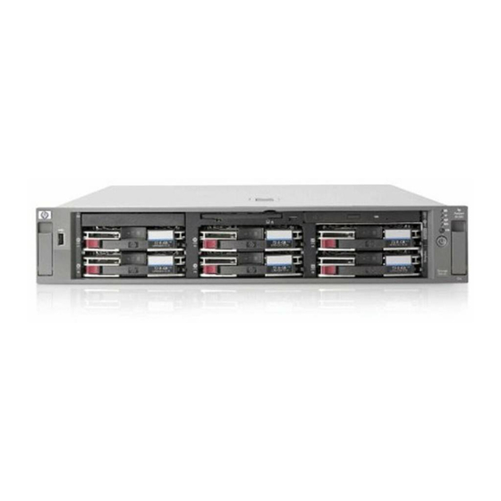
Page 6: Illustrated Parts Catalog
HP's customer self-repair program offers you the fastest service under either warranty or contract. It enables HP to ship replacement parts directly to you so that you can replace them. Using this program, you can replace parts at your own convenience. -
Page 7: Mechanical Components (Scsi Model)
Mechanical components (SCSI model) Item Description Original spare Modified Customer part number spare part self repair number Access panel 359244-001 — Front bezel 359245-001 — Tape drive blank 367666-001 — Hard drive blank 122759-001 — Diskette drive slot cover (see "Plastics Kit," —... -
Page 8: System Components (Scsi Model)
System components (SCSI model) Item Description Original spare Modified spare Customer self repair part number part number System components Hot-plug fan, 60 mm 289544-001 — Front fan bracket, 6 bay 371148-001 — Rear fan bracket, 2 bay 289558-001 — Hot-plug power supply, 400 W 338022-001‡... - Page 9 Item Description Original spare Modified spare Customer self repair part number part number e) 2.8-GHz Intel® Xeon™ 399132-001 — 2-MB L2 cache* ** f) 3.0-GHz Intel® Xeon™ 379427-001 — 2-MB L2 cache* ** g) 3.0-GHz Intel® Xeon™ 399764-001 — 2-MB L2 cache LV* ** h) 3.2-GHz Intel®...
- Page 10 Item Description Original spare Modified spare Customer self repair part number part number DVD-ROM drive, removable 268795-001‡ 397928-001 slimline, 8X* See requirement Cables SCSI cable kit* 289567-001 — — a) SCSI cable, short, 68 pin — — b) SCSI cable, long, 68 pin —...
- Page 11 Item Description Original spare Modified spare Customer self repair part number part number DVD/CD-ROM drive ejector 371114-001 — assembly* PCI expansion board ejector* 359261-001 — Battery, 3.3 V, lithium* 179322-001 — Country kit* 359722-001 — Return kit, pack box, and 289545-001 —...
-
Page 12: Mechanical Components (Sas Model)
If your unit contains a part that is labelled with the Original Spare number, please order the Original Spare as the replacement part in the EU. In this case either the Original Spare or the Modified Spare may be shipped which will not affect performance or functionality of the unit. -
Page 13: System Components (Sas Model)
System components (SAS model) Item Description Original spare Modified spare Customer self repair part number part number System component Hot-plug fan, 60 mm 289544-001 — Front fan bracket, 6 bay 371148-001 — Rear fan bracket, 2 bay 289558-001 — Hot-plug power supply, 338022-001‡... - Page 14 Item Description Original spare Modified spare Customer self repair part number part number g) 3.0-GHz Intel® Xeon™ 399764-001 — 2-MB L2 cache LV* ** h) 3.2-GHz Intel® Xeon™ 379428-001 — 2-MB L2 cache* ** i) 3.4-GHz Intel® Xeon™ 2- 379429-001 —...
- Page 15 Item Description Original spare Modified spare Customer self repair part number part number Signal cable kit* 228518-001 — — a) Power button/LED board — — cable, 14 pin b) PCI hot-plug LED board — — cable Miscellaneous cable kit* 366063-001 —...
- Page 16 Item Description Original spare Modified spare Customer self repair part number part number Return kit, pack box, and 289545-001 — cushions* T-15 Torx screwdriver* 199630-001 — Memory DIMM, 512 MB, registered 359241-001‡ 413384-001 DDR2 SDRAM* See requirement DIMM, 1 GB, registered 359242-001‡...
-
Page 17: Removal And Replacement Procedures
Required tools You need the following items for some procedures: • T-15 Torx screwdriver (provided inside the server) • HP Insight Diagnostics software ("HP Insight Diagnostics" on page 70) Safety considerations Before performing service procedures, review all the safety information. -
Page 18: Preparation Procedures
Extend the server from the rack (on page 19). If you are performing service procedures in an HP, Compaq branded, telco, or third-party rack cabinet, you can use the locking feature of the rack rails to support the server and gain access to internal components. -
Page 19: Extend The Server From The Rack
Extend the server from the rack Pull down the quick release levers on each side of the server to release the server from the rack. Extend the server on the rack rails until the server rail-release latches engage. WARNING: To reduce the risk of personal injury or equipment damage, be sure that the rack is adequately stabilized before extending a component from the rack. -
Page 20: Power Down The Server
The system is now without power. Remove the server from the rack To remove the server from an HP, Compaq branded, telco, or third-party rack: Power down the server (on page 20). Extend the server from the rack (on page 19). -
Page 21: Access The Product Rear Panel
Access the product rear panel Cable management arm with left-hand swing To access the server rear panel, open the cable management arm. To close the cable management arm, reverse this procedure. Cable management arm with right-hand swing NOTE: To access some components, you may need to remove the cable management arm. To access the product rear panel components, open the cable management arm. -
Page 22: Non-Hot-Plug Procedures
To close the cable management arm, reverse this procedure. Non-hot-plug procedures Access panel WARNING: To reduce the risk of personal injury from hot surfaces, allow the drives and the internal system components to cool before touching them. CAUTION: Do not operate the server for long periods with the access panel open or removed. Operating the server in this manner results in improper airflow and improper cooling that can lead to thermal damage. -
Page 23: Dvd/Cd-Rom Drive Ejector Assembly
DVD/CD-ROM drive ejector assembly To remove the component: Power down the server (on page 20). Extend or remove the server from the rack ("Extend the server from the rack" on page 19, "Remove the server from the rack" on page 20). Remove the access panel ("Access panel"... -
Page 24: Diskette Drive Option
Diskette drive option To remove the component: CAUTION: To prevent improper cooling and thermal damage, do not operate the server unless all bays are populated with either a component or a blank. Power down the server (on page 20). Extend or remove the server from the rack ("Extend the server from the rack"... -
Page 25: Front Fan Bracket
Remove the two screws and detach the front bezel. To replace the component, reverse the removal procedure. Front fan bracket To remove the component: Power down the server (on page 20). Extend or remove the server from the rack ("Extend the server from the rack"... -
Page 26: Rear Fan Bracket
Rear fan bracket To remove the component: Power down the server (on page 20). Extend or remove the server from the rack ("Extend the server from the rack" on page 19, "Remove the server from the rack" on page 20). Remove the access panel ("Access panel"... - Page 27 • Recovery of cached data from a failed server ("Recovering data from the battery-backed write cache" on page 29) CAUTION: Do not detach the cable that connects the battery pack to the cache module. Detaching the cable causes any unsaved data in the cache module to be lost. Smart Array 6i cache module To remove the component: Power down the server (on page 20).
- Page 28 Disconnect the cable. To replace the component, reverse the removal procedure. CAUTION: To prevent damage to the cache module during installation, be sure the cache module is fully inserted before pressing down. Battery-backed write cache battery pack To remove the component: Power down the server (on page 20).
- Page 29 Remove the BBWC enabler, also known as the battery pack. To replace the component, reverse the removal procedure. IMPORTANT: The battery pack might have a low charge when installed. In this case, a POST error message is displayed when the server is powered up, indicating that the battery pack is temporarily disabled.
-
Page 30: Pci Riser Cage Door Latch
• Install the BBWC into an empty BBWC DIMM socket on any Smart Array 641 or 642 Controller in the recovery server. Power up the recovery server. A 1759 POST message is displayed, stating that valid data was flushed from the cache. This data is now stored on the drives in the recovery server. You can now transfer the drives (and controller, if one was used) to another server. -
Page 31: Pci Riser Cage
PCI riser cage To remove the component: Power down the server (on page 20). Extend the server from the rack, if applicable ("Extend the server from the rack" on page 19). Remove the access panel ("Access panel" on page 22). CAUTION: To prevent damage to the server or expansion boards, power down the server and remove all AC power cords before removing or installing the PCI riser cage. -
Page 32: Expansion Slot Cover
Unlock the PCI retaining clip. Remove the expansion board. CAUTION: To prevent improper cooling and thermal damage, do not operate the server unless all PCI slots have either an expansion slot cover or an expansion board installed. To replace the component, reverse the removal procedure. Expansion slot cover To remove the component: Power down the server (on page 20). -
Page 33: Expansion Board Ejector/Divider
CAUTION: To prevent improper cooling and thermal damage, do not operate the server unless all PCI slots have either an expansion slot cover or an expansion board installed. Remove the expansion slot cover. To replace the component, reverse the removal procedure. Expansion board ejector/divider NOTE: This component is available only with the optional, hot-plug PCI riser cage. -
Page 34: Pci Slot Release Lever
Remove the expansion board ejector/divider. CAUTION: To prevent improper cooling and thermal damage, do not operate the server unless all PCI slots have either an expansion slot cover or an expansion board installed. To replace the component, reverse the removal procedure. PCI slot release lever To remove the component: Power down the server (on page 20). -
Page 35: Pci Lightpipe And Cover
Remove the PCI slot release lever. To replace the component, reverse the removal procedure. PCI lightpipe and cover NOTE: This component is available only with the optional, hot-plug PCI riser cage. To remove the component: Power down the server (on page 20). Extend or remove the server from the rack ("Extend the server from the rack"... -
Page 36: Power Converter Module
Slide the lightpipe out of the chassis. To replace the component, reverse the removal procedure. Power converter module To remove the component: Power down the server (on page 20). Extend or remove the server from the rack ("Extend the server from the rack"... -
Page 37: Power Button/Led Board
NOTE: Cables are removed for clarity. To replace the component, reverse the removal procedure. Power button/LED board To remove the component: Power down the server (on page 20). Extend or remove the server from the rack ("Extend the server from the rack"... -
Page 38: Dimms
Remove the DIMM. CAUTION: Be sure to install DIMMs in the proper configuration. Refer to the Documentation CD. CAUTION: Use only Compaq branded or HP DIMMs. DIMMs from other sources may adversely affect data integrity. IMPORTANT: DIMMs do not seat fully if turned the wrong way. -
Page 39: Ppm
To remove the component: Power down the server (on page 20). Extend or remove the server from the rack ("Extend the server from the rack" on page 19, "Remove the server from the rack" on page 20). Remove the access panel ("Access panel"... - Page 40 Open the processor retaining bracket. CAUTION: To prevent thermal instability and damage to the server, do not separate the processor from the heatsink. The processor, heatsink, and retaining clip make up a single assembly. Remove the processor and heatsink assembly. CAUTION: To prevent possible server malfunction and damage to the equipment, do not mix single- and dual-core processors or processors with different speeds or cache sizes.
-
Page 41: Battery
IMPORTANT: If upgrading processor speed, update the system ROM before installing the processor. IMPORTANT: Processor socket 1 and PPM slot 1 must be populated at all times or the server does not function properly. IMPORTANT: PPM slots must be populated when processors are installed. If PPM slots are not populated, the server halts during POST or does not boot. -
Page 42: System Board
Remove the battery. IMPORTANT: Replacing the system board battery resets the system ROM to its default configuration. After replacing the battery, reconfigure the system through RBSU. To replace the component, reverse the removal procedure. For more information about battery replacement or proper disposal, contact an authorized reseller or an authorized service provider. -
Page 43: Re-Entering The Server Serial Number And Product Id
Identify the alignment keys and keyhole locations, 1 through 4. Loosen the system board thumbscrew. Remove the system board. Remove the rear fan bracket. IMPORTANT: If replacing the system board or clearing NVRAM, you must re-enter the server serial number through RBSU ("Re-entering the server serial number and product ID"... -
Page 44: Hot-Plug Procedures
should only be used by qualified service personnel. This value should always match the serial number sticker located on the chassis. Press the Enter key to clear the warning. Enter the serial number and press the Enter key. Select Product ID. Enter the product ID and press the Enter key. -
Page 45: Hot-Plug Sas Hard Drive
NOTE: The server ships standard with five hard drive blanks. To replace the blank, slide the blank into the bay until it locks into place. Hot-plug SAS hard drive To remove the component: CAUTION: To prevent improper cooling and thermal damage, do not operate the server unless all bays are populated with either a component or a blank. -
Page 46: Sas Hard Drive Blank
SAS hard drive blank To remove the component: CAUTION: To prevent improper cooling and thermal damage, do not operate the server unless all bays are populated with either a component or a blank. To replace the blank, slide the blank into the bay until it locks into place. Universal hot-plug tape drive NOTE: This feature applies only to SCSI models. -
Page 47: Tape Drive Blank
Tape drive blank NOTE: This feature applies only to SCSI models. To remove the component: CAUTION: To prevent improper cooling and thermal damage, do not operate the server unless all bays are populated with either a component or a blank. Reach underneath and squeeze the middle of the tape drive blank. -
Page 48: Power Supply Blank
Remove the hot-plug power supply. To replace the component: WARNING: To reduce the risk of electric shock or damage to the equipment, do not connect the power cord to the power supply until the power supply is installed. Slide the hot-plug power supply into the power supply bay. Connect the power cord to the power supply. -
Page 49: Hot-Plug Fan
WARNING: To reduce the risk of personal injury from hot surfaces, allow the power supply or power supply blank to cool before touching it. To replace the blank, slide the blank into the bay until it locks into place. Hot-plug fan WARNING: To reduce the risk of electric shock, personal injury, and damage to the equipment: •... -
Page 50: Pci Hot Plug Expansion Board
Remove the non-functioning fan. CAUTION: Do not operate the server for long periods with the access panel open or removed. Operating the server in this manner results in improper airflow and improper cooling that can lead to thermal damage. IMPORTANT: For optimum cooling, install fans in all primary fan locations. For more information, refer to the fan locations table ("Identifying hot-plug fans"... - Page 51 Open the PCI riser cage door. Press the PCI Hot Plug button ("Internal PCI Hot Plug LEDs and button" on page 90) to remove power from the slot. When the green power LED on the slot stops flashing, power has been removed from the slot.
-
Page 52: Pci Hot Plug Expansion Slot Cover
Remove the expansion board. To replace the component, reverse the removal procedure. PCI Hot Plug expansion slot cover NOTE: Hot-plug functionality is supported only under Microsoft® Windows® 2000 and Windows® 2003. Hot- plug drivers are not required. To remove the component: CAUTION: If the operating system installed on the server does not support PCI Hot Plug functionality, power down the server (on page 20) before removing expansion boards. - Page 53 Press the PCI Hot Plug button ("Internal PCI Hot Plug LEDs and button" on page 90) to remove power from the slot. When the green power LED on the slot stops flashing, power has been removed from the slot. CAUTION: To prevent improper cooling and thermal damage, do not operate the server unless all PCI slots have either an expansion slot cover or an expansion board installed.
-
Page 54: Cabling
This section provides guidelines that help you make informed decisions about cabling the server and hardware options to optimize performance. For information on cabling the optional RILOE II board, refer to the HP Remote Insight Lights-Out Edition II User Guide on the Documentation CD. -
Page 55: Usb Cabling
NOTE: If storage devices are connected to both the internal (1I) and external (1E) SAS connectors, the SAS controller recognizes only the devices connected to the internal connector. To attach devices to the external connector, disconnect the internal connector. Refer to the documentation that documentation that ships with the controller. -
Page 56: Dvd/Cd-Rom Drive Cabling
DVD/CD-ROM drive cabling Item Cable description DVD/CD-ROM drive cable DVD/CD-ROM drive system cable Diskette drive cabling Item Cable description Diskette drive cable Diskette drive system cable Cabling 56... -
Page 57: Power Button/Led Cabling
Power button/LED cabling The power button/LED cable connects the power button/LED board to the SAS backplane. Optional PCI Hot Plug backplane cabling The server contains a PCI Hot Plug backplane that is part of the PCI Hot Plug option and provides hot-plug capability for two expansion slots. -
Page 58: Riloe Ii Cabling
RILOE II cabling The 30-pin Remote Insight cable ships with the RILOE II cable kit. For more information, refer to the Remote Insight Lights-Out Edition II User Guide on the Documentation CD. Internal power cabling Item Description System power cable Power supply signal cable SAS power cable SCSI model cabling... -
Page 59: Embedded Simplex Scsi Cabling
NOTE: The server ships with two identical short SCSI cables. Two optional long SCSI cables may be obtained for PCI Array Controllers. One optional terminator board may be obtained to support duplex SCSI configurations. Embedded simplex SCSI cabling In the embedded simplex cabling configuration, the embedded Smart Array 6i Controller controls up to six hard drives through one SCSI bus. -
Page 60: Pci Simplex Scsi Cabling
NOTE: This specific cabling configuration does not support external VHDCI. NOTE: Optional SCSI terminator board and optional long SCSI cables are available in the SCSI Configuration Option Kit. NOTE: The short SCSI cables are identical. Item Component description SCSI IDs managed Short SCSI cable 0, 1 Short SCSI cable... -
Page 61: Pci Duplex Scsi Cabling
NOTE: Optional SCSI terminator board and optional long SCSI cables are available in the SCSI Configuration Option Kit. Item Component description SCSI IDs managed Optional long SCSI cable 0, 1, 2, 3, 4, 5 Short SCSI cable used to jumper the two SCSI buses together PCI duplex SCSI cabling In the PCI duplex cabling configuration, an optional PCI array controller controls up to six hard drives... - Page 62 NOTE: This specific cabling configuration does not support external VHDCI. NOTE: Optional SCSI terminator board and optional long SCSI cables are available in the SCSI Configuration Option Kit. Item Component description SCSI IDs managed Optional long SCSI cable 0, 1 Short SCSI cable 2, 3, 4, 5 Optional terminator board...
-
Page 63: Installing The Scsi Terminator Board
Item Component description SCSI IDs managed Optional terminator board Refer to "Installing the SCSI Terminator Board (on page 63)" for SCSI terminator board installation procedures. Installing the SCSI terminator board Power down the server (on page 20). Extend or remove the server from the rack ("Extend the server from the rack"... -
Page 64: Usb Cabling
Remove the SCSI terminator board. USB cabling The USB cable connects the front panel USB connector to the SCSI backplane. Cabling 64... -
Page 65: Dvd/Cd-Rom Drive Cabling
DVD/CD-ROM drive cabling Item Cable description DVD/CD-ROM drive cable DVD/CD-ROM drive system cable Diskette drive cabling Item Cable description Diskette drive cable Diskette drive system cable Cabling 65... -
Page 66: Power Button/Led Cabling
Power button/LED cabling The power button/LED cable connects the power button/LED board to the SCSI backplane. Optional PCI Hot Plug backplane cabling The server contains a PCI Hot Plug backplane that is part of the PCI Hot Plug option and provides hot-plug capability for two expansion slots. -
Page 67: Riloe Ii Cabling
RILOE II cabling The 30-pin Remote Insight cable ships with the RILOE II cable kit. For more information, refer to the Remote Insight Lights-Out Edition II User Guide on the Documentation CD. Internal power cabling Item Description System power cable Power supply signal cable SCSI power cable Cabling 67... -
Page 68: External Storage Cabling
After cabling external storage options, use the following software utilities: • RBSU, to configure new hardware in the system For more information, refer to "HP ROM-Based Setup Utility (on page 72)" or the ROM-Based Setup Utility User Guide on the Documentation CD. •... -
Page 69: Diagnostic Tools
To obtain the guide, refer to any of the following sources and then select the HP ProLiant Servers Troubleshooting Guide: •... -
Page 70: Hp Insight Diagnostics
ASR increases server availability by restarting the server within a specified time after a system hang or shutdown. At the same time, the HP SIM console notifies you by sending a message to a designated pager number that ASR has restarted the system. You can disable ASR from the HP SIM console or through RBSU. -
Page 71: Hp Systems Insight Manager
HP SIM provides device management capabilities that consolidate and integrate management data from HP and third-party devices. IMPORTANT: You must install and use HP SIM to benefit from the Pre-Failure Warranty for processors, SAS and SCSI hard drives, and memory modules. -
Page 72: Hp Rom-Based Setup Utility
It enables you to perform imaging or scripting functions and maintain software images. For more information about the RDP, refer to the HP ProLiant Essentials Rapid Deployment Pack CD or refer to the HP website (http://www.hp.com/servers/rdp). -
Page 73: System Online Rom Flash Component Utility
Integrates with other software maintenance, deployment, and operating system tools • Automatically checks for hardware, firmware, and operating system dependencies, and installs only the correct ROM upgrades required by each target server To download the tool and for more information, refer to the HP website (http://h18000.www1.hp.com/support/files/index.html). Diagnostic tools 73... -
Page 74: Component Identification
Component identification In this section Front panel components .......................... 75 Front panel LEDs and buttons ........................76 Rear panel components........................... 77 Rear panel LEDs and buttons ........................78 System board components........................79 SCSI backplane components ........................81 SAS backplane components ........................82 System board LEDs .......................... -
Page 75: Front Panel Components
Front panel components Item SCSI model (top) SAS model (bottom) Hard drive bays Hard drive bays USB port USB port Bay for tape drive or hard drive with — tape drive blank Diskette drive bay Diskette drive bay DVD/CD-ROM drive DVD/CD-ROM drive Component identification 75... -
Page 76: Front Panel Leds And Buttons
Front panel LEDs and buttons Item Description Status Internal health LED Green = Normal Amber = System degraded. Refer to system board LEDs to identify component in degraded state. Red = System critical. Refer to system board LEDs to identify component in critical state. -
Page 77: Rear Panel Components
Rear panel components Item Description Color • Hot-plug or non-hot-plug PCI-X expansion slot 3, 64 bit/100 MHz, bus B • PCI Express x4 slot 2, bus B* • Hot-plug or non-hot-plug PCI-X expansion slot 2, 64 bit/100 MHz, bus B •... -
Page 78: Rear Panel Leds And Buttons
Rear panel LEDs and buttons Item Description LED Color Status PCI Hot Plug fault LED (slot 3)* Amber On = Expansion board failed Off = Normal PCI Hot Plug power LED Green On = Power is applied to the slot (slot 3)* Flashing = Power is cycling Off = Power is not applied to the slot... -
Page 79: System Board Components
System board components Item Description Item Description Smart Array 6i Cache Diskette drive system connector Module Option* Chassis ID switch DIMM slots (1-6) System maintenance switch Power supply signal connector PPM slot 2 Fan 6 connector PCI riser cage connector System power connector SCSI connector (port 2)* PPM slot 1... -
Page 80: Nmi Switch
Position Default Function Off = No function On = Clears power-on password and administrator password. Off = No function On = Clear NVRAM. When the system maintenance switch position 6 is set to the On position, the system is prepared to erase all system configuration settings from both CMOS and NVRAM. -
Page 81: Scsi Backplane Components
Item Description DIMM slot 1A DIMM slot 2A DIMM slot 3B DIMM slot 4B DIMM slot 5C DIMM slot 6C SCSI backplane components Item Description Power button/LED connector SCSI connector (port 2) DVD/CD-ROM drive connector SCSI connector (port 1) Diskette drive connector Power connector USB connector Diskette drive system connector... -
Page 82: Sas Backplane Components
SAS backplane components Item Description Power button/LED connector DVD/CD-ROM drive connector DVD/CD-ROM drive system connector SAS connector Diskette drive system connector Diskette drive connector SAS connector Power connector USB connector System board LEDs Component identification 82... -
Page 83: System Leds And Internal Health Led Combinations
Off = Disabled PPM 1 failure Amber = PPM failed Off = Normal iLO diagnostic LEDs Refer to the HP Integrated Lights-Out User Guide on the Documentation CD. Processor 1 failure Amber = Processor failed Off = Normal Processor 2 failure... - Page 84 The front panel health LEDs indicate only the current hardware status. In some situations, HP SIM may report server status differently than the health LEDs because the software tracks more system attributes. System LED and color Internal health LED Status...
-
Page 85: Scsi Backplane Leds
SCSI backplane LEDs Item LED description Status SCSI configuration On = Simplex Off = Duplex SCSI configuration error On = SCSI cabling or terminator configuration is incorrect Off = SCSI cabling or terminator configuration is correct Hot-plug SCSI hard drive LEDs Component identification 85... -
Page 86: Hot-Plug Scsi Hard Drive Led Combinations
The drive is part of an array being selected by an array configuration utility • Drive Identification has been selected in HP SIM • The drive firmware is being updated The drive has been placed offline due to hard disk drive failure or subsystem communication failure. -
Page 87: Hot-Plug Sas Hard Drive Leds
Activity Online LED Fault LED Interpretation LED (1) One or more of the following conditions may exist: • The drive is not configured as part of an array • The drive is configured as part of an array, but it is a replacement drive that is not being accessed or being rebuilt yet •... -
Page 88: Pci Hot Plug Led Status Combinations
The power to the slot is on, but the slot needs attention for a possible problem with the slot, board, or driver. DO NOT open the slot release lever. Examine the logs and HP SIM. If the expansion board is faulty, remove or replace the board. Flashing... -
Page 89: Pci Riser Cage Led
PCI riser cage LED CAUTION: To prevent damage to the server or expansion boards, power down the server and remove all AC power cords before removing or installing the PCI riser cage. Status On = AC power connected Off = AC power disconnected Remote management connector The 30-pin remote management connector, located on the PCI riser cage, is used to cable the Remote Insight Lights-Out Edition II option. -
Page 90: Internal Pci Hot Plug Leds And Button
Internal PCI Hot Plug LEDs and button NOTE: Hot-plug LEDs are available only with the optional hot-plug PCI riser cage. Item Description Status Fault LED (Amber) On = Expansion board failed. Off = Normal Power LED (Green) On = Power is applied to the slot. Flashing = Power is cycling. -
Page 91: Hot-Plug Fan Led
Item Description Configuration Fan 2 Primary Fan 3 Redundant Fan 4 Primary Fan 5 Primary Fan 6 Primary Fan 7 Primary Fan 8 Redundant Hot-plug fan LED Status Green = Operating normally Amber = Failed Off = No power Component identification 91... -
Page 92: Power Converter Module Led
Power converter module LED Status Amber = Failed Off = Operating normally Battery-backed write cache LEDs NOTE: This feature applies only to SCSI models. Item LED color Amber Green For LED status information, refer to "Battery-backed write cache LED statuses (on page 93)." Component identification 92... -
Page 93: Battery-Backed Write Cache Led Statuses
Battery-backed write cache LED statuses NOTE: This feature applies only to SCSI models. Server status LED status Battery module status Server is on and has normal run Green = On Fast charging time Green = Flashing The microcontroller is waiting for communication from the host controller. -
Page 94: Specifications
Specifications In this section Server specifications ..........................94 Environmental specifications ........................94 Hot-plug power supply calculations ......................95 DDR2 SDRAM DIMM specifications......................95 1.44-MB diskette drive specifications......................95 CD-ROM drive specifications ........................96 DVD-ROM drive specifications ......................... 97 Ultra320 SCSI hard drive specifications....................98 SAS and SATA hard drive specifications.................... -
Page 95: Hot-Plug Power Supply Calculations
72 bits Upgrade requirement * Any combination of like-paired DDR2 DIMMs that provide a minimum of 512 MB *Use only 512-MB, 1-GB, or 2-GB, 72-bit wide, 1.8-V, PC2-3200 Registered ECC DDR2. Use HP DDR2 only. 1.44-MB diskette drive specifications Specification Value... -
Page 96: Cd-Rom Drive Specifications
Specification Value High 500 Kb/s 250 Kb/s Bytes/sector Sectors per track (high/low) 18/9 Tracks per side (high/low) 80/80 Access times Track-to-track (high/low) 3 ms/6 ms Average (high/low) 169 ms/94 ms Setting time 15 ms Latency average 100 ms Cylinders (high/low) 80/80 Read/write heads CD-ROM drive specifications... -
Page 97: Dvd-Rom Drive Specifications
Specification Value Laser parameters Type Semiconductor laser GaAs Wave length 700 ± 25 nm Divergence angle 53.5° ± 1.5° Output power 0.14 mW Operating conditions Temperature 5°C to 45°C (41°F to 118°F) Humidity 5% to 90% DVD-ROM drive specifications Specification Value DVD (single and double layer), DVD-5, DVD-9, DVD-10, DVD-R, CD-ROM Mode Disk formats... -
Page 98: Ultra320 Scsi Hard Drive Specifications
Specification Value Laser parameters Type Semiconductor laser GaAs Wave length 700 ± 25 nm Divergence angle 53.5° ± 1.5° Output power 0.14 mW Operating conditions Temperature 5°C to 45°C (41°F to 118°F) Humidity 5% to 90% Ultra320 SCSI hard drive specifications Item 36.4-GB Ultra320 72.8-GB Ultra320... -
Page 99: Acronyms And Abbreviations
Acronyms and abbreviations ABEND abnormal end Automatic Server Recovery BBWC battery-backed write cache BIOS Basic Input/Output System double data rate DIMM dual inline memory module integrated device electronics Integrated Lights-Out Integrated Management Log light-emitting diode non-maskable interrupt NVRAM non-volatile memory Acronyms and abbreviations 99... - Page 100 ORCA Option ROM Configuration for Arrays peripheral component interface PCI Express peripheral component interconnect express PCI-X peripheral component interconnect extended POST Power-On Self Test processor power module RBSU ROM-Based Setup Utility Remote Desktop Protocol RILOE II Remote Insight Lights-Out Edition II serial attached SCSI SATA serial ATA...
- Page 101 unit identification universal serial bus VHDCI very high density cable interconnect Acronyms and abbreviations 101...
-
Page 102: Index
(CSR) 6 health LEDs 76, 80, 85 HP Insight Diagnostics 17, 70 HP ProLiant Essentials Foundation Pack 71 HP ProLiant Essentials Rapid Deployment Pack 71 DC power supply 78 HP Systems Insight Manager, overview 71 deployment software 71... - Page 103 iLO connector 77 power cord connector 77 IML (Integrated Management Log) 70 power LEDs, system 76 Insight Diagnostics 70 Power On/Standby button 66, 76 Integrated Lights-Out (iLO) 71, 99 power requirements 95 Integrated Management Log (IML) 70 power supplies 78, 95 internal health LED 76, 83 power supply blank 48 power supply LEDs 78, 92...
- Page 104 SmartStart, overview 72 specifications 94, 95, 96, 97 specifications, environmental 94 specifications, server 94, 95, 98 static electricity 17 Survey Utility 70 system board components 77 system board LEDs 82, 83 system components 8, 13 system maintenance switch 77, 79, 80 system power LED 76 Systems Insight Manager 71 telco racks 18, 20...
Need help?
Do you have a question about the DL380 Generation 4 and is the answer not in the manual?
Questions and answers