Table of Contents
Advertisement
Advertisement
Table of Contents

Related Manuals for Getac Notebook computer


Summary of Contents for Getac Notebook computer
- Page 1 User’s Manual (December 2007)
- Page 2 TRADEMARKS ® The Bluetooth word mark and logos are registered trademarks owned by Bluetooth SIG, Inc. All other brand and product names are trademarks or registered trademarks of their respective owners. NOTE The information in this manual is subject to change without notice.
- Page 3 ® ENERGY STAR is a government program that offers businesses and consumers energy-efficient solutions, making it easy to save money while protecting the environment for future generations. ® Please reference ENERGY STAR related information from www.energystar.gov. As an ENERGY STAR® Partner, MiTAC Technology Corporation has ®...
- Page 4 ® Over its lifetime, ENERGY STAR qualified equipment in a single home office (e.g., computer, monitor, printer, and fax) can save enough electricity to light an entire home for more than 4 years. Power management (“sleep settings”) on computers and monitors can result in much savings annually.
-
Page 5: Table Of Contents
Table of Contents Preface ..................vi Chapter 1 Getting Started...........1-1 Getting the Computer Running ..........1-2 Unpacking ................ 1-2 Connecting to AC Power ..........1-2 Opening the Cover ............1-4 Turning On and Off the Computer........1-4 Taking a Look at the Computer..........1-6 Right-Side Components ........... - Page 6 Hot Keys ................2-7 Using the Touchpad ............2-10 Configuring the Touchpad ..........2-12 Using the Touchscreen (Optional) ........2-12 Using the Hard Disk Drive..........2-15 Using the Optical Drive............2-16 Inserting and Removing a Disc ........2-17 Using the Video Features ........... 2-18 Configuring the Display Modes ........
- Page 7 Connecting an IEEE 1394 Device........4-6 Using PC Cards ..............4-9 PC Card Type..............4-9 CardBus Support .............. 4-9 Inserting and Removing a PC Card........4-9 Using ExpressCards ............4-11 ExpressCard Type ............4-11 Inserting and Removing an ExpressCard ....... 4-12 Using the Card Reader ............
- Page 8 Cleaning Guidelines ............7-5 Battery Pack Guidelines ........... 7-5 Touchscreen Guidelines ........... 7-6 When Traveling..............7-8 Chapter 8 Troubleshooting..........8-1 Preliminary Checklist ............8-2 Solving Common Problems..........8-3 Battery Problems.............. 8-4 Bluetooth Wireless Transmission Problems..... 8-4 Display Problems ............. 8-5 ExpressCard Problems ............. 8-6 Hardware Device Problems..........
- Page 9 European Union CE Marking and Compliance Notices ..B-9...
-
Page 10: Preface
Preface This manual contains information that will help you operate the computer. It is divided into 8 chapters and 2 appendices. Chapter 1, Getting Started, takes you through the process of setting up the computer and identifying its external components. Chapter 2, Operating Your Computer, tells you how to use the computer’s components and features. -
Page 11: Notational Conventions
Notational Conventions Throughout this manual, the following conventions are used to distinguish elements of text. NOTE: identifies additional information that requires special attention. CAUTION: identifies important information that, if not followed, may result in loss of data or damage to the computer. Keyboard keys are shown in a bold typeset. -
Page 12: Getting Started
Chapter 1 CHAPTER Getting Started Congratulations on purchasing this rugged computer. This chapter first tells you step by step how to get the computer up and running. You will find instructions for these procedures: Unpacking Connecting to AC power Opening and closing the cover Turning on the computer Turning off the computer Then, you will find a section briefly introducing the external components... -
Page 13: Getting The Computer Running
This section guides you through the procedures for getting the computer ready for operation. Unpacking After unpacking the shipping carton, you should find these standard items: Notebook computer Accessories: − AC adapter − AC power cord − Stylus (option) Inspect all the items. If any item is damaged or missing, notify your dealer immediately. - Page 14 3. Plug the female end of the AC power cord to the AC adapter and the male end to an electrical outlet ( ). 4. When the AC adapter is connected, power is being supplied from the electrical outlet to the AC adapter and onto your computer. Now, you are ready to turn on the computer.
-
Page 15: Opening The Cover
Opening the Cover CAUTION: Be gentle when opening and closing the cover. Opening it vigorously or slamming it shut could damage the computer. Open the top cover by pulling on the cover latch ( ) and lifting up the cover ( ). You can tilt the cover forward or backward for optimal viewing clarity. - Page 16 2. Press the power button ( ) and the operating system such as Windows should start. Turning Off To turn off the computer power, use the “Shut Down” command of your operating system. NOTE: There are other ways you can stop the computer so that you will be back to where you left off when you next turn on the computer.
-
Page 17: Taking A Look At The Computer
Taking a Look at the Computer This section identifies the external components of the computer and briefly describes the function of each component. NOTE: Depending on the model you purchased, the appearance of your computer may not be exactly the same as those shown in this manual. Right-Side Components Component Description... -
Page 18: Left-Side Components
Left-Side Components Component Description See Also Connects an external microphone. P. 2-21 Microphone Connector Connects a set of headphones, external P. 2-21 Audio Output speakers with amplifier, or an audio recording Connector device. RF (radio Turns the wireless LAN radio, Bluetooth P. - Page 19 Component Description See Also Power Connector Connects the AC adapter. P. 1-2 RJ-11 Connector Connects the telephone line. P. 2-22 RJ-45 Connector Connects the LAN cable. P. 2-23 Accepts a MultiMediaCard (MMC), Secure P. 4-13 Card Reader Digital (SD), Memory Stick (MS) or Memory Stick PRO (MS PRO) card for removable storage media.
-
Page 20: Rear Components
Rear Components Component Description See Also Serial Connector Connects a serial mouse or serial P. 4-4 communication device. Supplies power to your computer when P. 3-3 Battery Pack external power is not connected. Connects an external display monitor. P. 4-2 VGA Connector Kensington Lock Locks the computer to a stationary object for P. -
Page 21: Front Components
Front Components Component Description See Also Top Cover Latch Locks the top cover. P. 1-4 Provides a convenient way to carry the Handle computer anywhere. Getting Started 1-10... -
Page 22: Bottom Components
Bottom Components Component Description See Also Inside are the memory slots for expanding P. 4-16 Memory Slots the memory size of your computer. Inside is the mini PCI-E slot for using a P. 2-24 Wireless LAN mini PCI-E WLAN card. (WLAN) Card Slot Inside is the CPU. -
Page 23: Top-Open Components
Top-open Components Component Description See Also Allows you to use your computer’s camera CMOS Camera function. Lens Receives sound and voice for the computer. P. 2-20 Microphone Displays the output of the computer. P. 2-18/ LCD Screen/ 2-12 Touchscreen (option) Getting Started 1-12... - Page 24 Component Description See Also Quick Buttons Enables/disables sunlight readable display. P. 2-18 Enables/disables power saving when using P. 2-4 battery power. P1 (Program 1 – user customized) quick launch P. 6-2 key. Default is Microsoft® Internet Explorer. P2 (Program 2 – user customized) quick launch P.
- Page 25 Component Description See Also Num Lock indicator P. 2-5 Caps Lock indicator P. 2-5 Power saving mode indicator WLAN indicator P. 2-25 ® feature indicator Bluetooth WWAN indicator Fingerprint Sensor Serves as the fingerprint verification, preventing unauthorized access to your computer.
-
Page 26: Where To Go From Here
Where to Go from Here As your computer is ready for operation, you may want to do any of the following now: For this purpose... Do this... To know more about the computer... Go on to the next chapter. To install the operating system if your See the operating system manual. -
Page 27: Operating Your Computer
Chapter 2 CHAPTER Operating Your Computer This chapter provides information about the use of the computer. If you are new to computers, reading this chapter will help you learn the operating basics. If you are already a computer user but are new to notebook computers, you may choose to read only the parts containing information unique to your computer. -
Page 28: Starting And Stopping The Computer
Starting and Stopping the Computer There are a number of ways to start and stop the computer. Starting the Computer You always start the computer using the power button. A computer starts up with an operating system (OS) existing on the storage device such as the hard disk. - Page 29 To stop in Do this... To start up or this mode... resume again Hibernation Depending on your settings in Windows, Press the power you can place the computer in button. Hibernation mode by: • Closing the display cover • Pressing the power button If you choose to stop in Sleep/Standby or Hibernation mode, you can return to where you left off the next time you start up the computer.
-
Page 30: Using The Quick Buttons
Using the Quick Buttons Located on top of the keyboard are five quick buttons: Sunlight readable quick button ( ) for enabling the sunlight readable LCD display. Power saving quick button ( ) to enter into power saving mode when using battery power. The system will turn down the panel backlight and sacrifice processing speed to gain more battery life. -
Page 31: Using The Internal Keyboard
Using the Internal Keyboard Your keyboard has all the standard functions of a full-sized computer keyboard plus a key added for specific functions. The standard functions of the keyboard can be further divided into four major categories: Typewriter keys Cursor-control keys Numeric keys Function keys Typewriter Keys... -
Page 32: Cursor-Control Keys
Cursor-Control Keys NOTE: The word “cursor” refers to the indicator on the screen that lets you know exactly where on your screen anything you type will appear. It can take the form of a vertical or horizontal line, a block, or one of many other shapes. Numeric Keypad A 15-key numeric keypad is embedded in the typewriter keys as shown next:... -
Page 33: Function Keys
NOTE: When the numeric keypad is activated and you need to type the English letter in the keypad area, you can turn Num Lock off or you can press Fn and then the letter without turning Num Lock off. Some software may not be able to use the numeric keypad on the computer. If so, use the numeric keypad on an external keyboard instead. - Page 34 Description Decreases the sound volume. Increases the sound volume. Switches the display output to one of the following when external devices are connected. Upon booting the system with CRT: LCD & CRT NOTE: This function only applies to Plug & Play display devices.
-
Page 35: Euro Symbol
Euro Symbol You can press the euro dollar sign on various keyboards. To press the euro sign on a United States-International keyboard, hold down the Alt Gr key and press (which has an euro sign on it). To press the euro sign on a standard United States keyboard, hold down either of the keys and type 0128... -
Page 36: Using The Touchpad
Using the Touchpad CAUTION: Do not use a sharp object such as a pen on the touchpad. Doing so may damage the touchpad surface. NOTE: Press Fn+F9 to toggle the touchpad on or off. For optimal performance of the touchpad, keep your fingers and the pads clean and dry. - Page 37 The touchpad consists of a rectangular pad (work surface) and a left and right buttons. To use the touchpad, place your forefinger or thumb on the pad. The rectangular pad acts like a miniature duplicate of your display. As you slide your fingertip across the pad, the pointer (also called cursor) on the screen moves accordingly.
-
Page 38: Configuring The Touchpad
Term Action Scroll To scroll is to move up and down or left and right in the working area on the screen. To move vertically, place your finger on the right edge of the pad and slide your finger up and down along the edge. To move horizontally, place your finger on the bottom edge of the pad and slide your finger left and right. -
Page 39: Using The Touchscreen (Optional)
Using the Touchscreen (Optional) NOTE: Make sure the touchscreen driver has been installed properly. Press Fn+F8 to toggle the touchscreen on or off. CAUTION: Do not use a sharp object such as a ballpoint pen or pencil on the touchscreen. Doing so may damage the touchscreen surface. Use your finger or the included touchscreen pen (option). -
Page 40: Touchscreen Calibration
Term Action Drag and Press lightly on the touchscreen and move your finger/ drop touchsreen pen until you reach your destination (drag). Finally, release your finger/touchscreen pen (drop) when you finish dragging your selection to the destination. The object will drop into the new location. Touchscreen Calibration To calibrate your touchscreen display, perform the following steps: 1. -
Page 41: Using The Hard Disk Drive
Using the Hard Disk Drive Your computer comes with a removable hard disk drive as drive C. A hard disk drive is a storage device with non-removable, rotating, magnetic storage platters inside it. It is where your operating system and application software programs are stored. -
Page 42: Using The Optical Drive
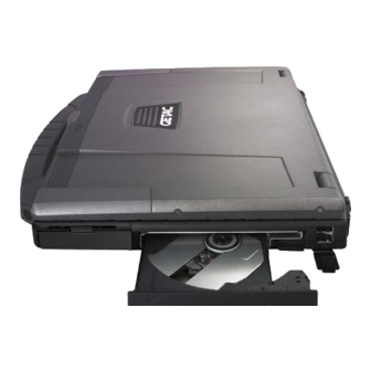
Using the Optical Drive Your computer comes with an optical drive, usually configured as drive Depending on the model, your drive is one of the following: Combo drive can work both as a DVD drive (reading DVD discs in addition to CDs, audio CDs and CD-R/-RW discs), and also as a CD recorder (writing to CD-R/-RW discs). -
Page 43: Inserting And Removing A Disc
Inserting and Removing a Disc Follow this procedure to insert or remove a disc: 1. Turn on the computer. 2. Press the optical drive quick button ( ) and the drive tray will slide out partially. Gently pull on it until it is fully extended. 3. -
Page 44: Using The Video Features
Using the Video Features The video subsystem of your computer features: 14.1-inch wide TFT (Thin-Film Transistor) color LCD display with 1280×800 WXGA resolution or 1440×900 WXGA+ resolution Multi-display capability, which allows you to expand your desktop on the screen to another display device so that you have more desktop space to work on Sunlight-readable LCD display by pressing sunlight readable quick button (... - Page 45 For displaying in higher resolutions, you can connect an external monitor that supports higher resolutions. (See “Connecting an External Monitor” in Chapter 4 for more information.) Operating Your Computer 2-19...
-
Page 46: Using The Audio Features
Using the Audio Features NOTE: To take advantage of the enhanced audio capabilities, the device driver supplied with your computer must be installed. If you experience interference while recording, try lowering the microphone recording volume. The audio subsystem of your computer features: Azalia interface (high density audio codec) Built-in microphone ( ) Set of speakers ( ) and... -
Page 47: Connecting Audio Devices
Ways of playing and recording sound vary with the operating system used. See your operating system documentation or online help for specific information. Connecting Audio Devices For higher audio quality, you can send or receive sound through external audio devices. NOTE: After connecting an external audio device, make sure that you specify the use of the correct audio device in Windows. -
Page 48: Using The Communication Features
Using the Communication Features Using the Modem NOTE: To take advantage of the modem feature, the device driver supplied with your computer must be installed. The internal 56 K fax/data modem allows you to use the telephone line to communicate with others by fax, email, or connect to an online service or bulletin board. -
Page 49: Using The Lan
Using the LAN NOTE: To take advantage of the LAN feature, the device driver supplied with your computer must be installed. The internal 10/100/1000Base-T LAN (Local Area Network) module allows you to connect your computer to a network. It supports data transfer rate up to 1000 Mbps. -
Page 50: Using The Wireless Lan
Using the Wireless LAN Depending on your model, an internal mini PCI-E wireless LAN (WLAN) card may have been pre-installed by your computer manufacturer at the factory. This card allows you to access corporate networks or the Internet in a wireless environment. The WLAN features include: Peer-to-Peer (Ad-Hoc) and Access Point (Infrastructure) modes support... - Page 51 Turning Off/On the WLAN Radio NOTE: The FAA (Federal Aviation Agency) has deemed it unsafe to operate wireless devices in aircraft as this may interfere with flight safety. Remember to turn off wireless LAN when using your computer in the airplane. 1.
- Page 52 3. If any wireless network is detected, the following window appears on screen. Click the Show drop down menu and select Wireless. 4. Select a wireless network to connect to by clicking a selection, then click Connect. 5. Depending on the settings, you may be asked to enter a WEP key (refer to your Windows online help for more information on setting a wireless network connection).
- Page 53 2. Double-click the Wireless Network Connection icon located on your Windows system tray. If any wireless network is detected, the following window appears on screen. 3. Select a wireless network to connect to by clicking a selection, then click Connect. 4.
-
Page 54: Using The Bluetooth ® Feature (Optional)
Using the Bluetooth Feature (Optional) ® NOTE: To take advantage of the Bluetooth feature, the Bluetooth driver supplied with your computer must be installed. Depending on your model, your computer may incorporate the Bluetooth capability for short-range (about 10 meters) wireless communications between devices without requiring a cable connection. - Page 55 The status of the Bluetooth connection is indicated by the Bluetooth icon located in the system tray in the lower-right part of the screen. Status Icon (blue with red logo) (blue with white logo). Connected (blue with green logo) You can use the Bluetooth Utility to configure Bluetooth wireless connection settings and transfer files.
-
Page 56: Connecting To Another Bluetooth Device
2. Select to enable all items and then click OK to save the change. Connecting to Another Bluetooth Device 1. Make sure that the target Bluetooth device is turned on, discoverable and within close range. (See the documentation that came with the Bluetooth device.) icon, and then click Add New Connection. - Page 57 3. The Add New Connection Wizard window appears. Select Express Mode (Recommended), and then click Next. 4. Select the device to connect to and click Next. Operating Your Computer 2-31...
- Page 58 5. Depending on the type of Bluetooth device that you want to connect to, you will need to enter the pertinent information. Sending a File 1. Make sure that the target Bluetooth device is turned on, discoverable and within close range. (See the documentation that came with the Bluetooth device.) icon, and then click Wireless File Transfer.
- Page 59 4. Click the target device from the list, and then click Send to start the transfer procedure. Operating Your Computer 2-33...
-
Page 60: Using The Gps (Optional)
Using the GPS (Optional) NOTE: To take advantage of the GPS feature, the GPS driver supplied with your computer must be installed. You may need to install third-party software to fully take advantage of the GPS feature. Navigation and positioning are crucial to so many activities. To try to figure out where you are and where you are going, you need GPS technology. -
Page 61: Using The 3G Feature (Optional)
For detailed information on using the GPS Utility, see the GPS Utility Help on your computer by clicking on Help. Using the 3G Feature (Optional) 3G is the third generation of mobile phone standards and technology, after 2G. It is based on the International Telecommunication Union (ITU) family of standards under the International Mobile Telecommunications programme, “IMT-2000”. - Page 62 4. Slide the battery release lever outward to the unlock ( ) position ( ) and, while holding it in the unlock position, remove the battery pack off the computer ( ). 5. Locate the SIM card slot and slide the SIM card holder towards the left to release it.
- Page 63 6. Lift the SIM card holder. 7. Slide the SIM card into the holder making sure the beveled corner on the SIM card is facing upwards and that the golden contact area on the card will be facing downwards when holder is closed. Operating Your Computer 2-37...
- Page 64 8. Slide the holder towards the right to secure the SIM card in place. 9. Fit the battery pack into place and slide the battery security lock to the lock ( ) position. WARNING: Keep all SIM cards out of the reach of small children. For availability and information on using SIM card services, contact your SIM card vendor.
-
Page 65: Managing Power
Chapter 3 CHAPTER Managing Power Your computer operates either on external AC power or on internal battery power. This chapter tells you how you can effectively manage power. To maintain optimal battery performance, it is important that you use the battery in the proper way. -
Page 66: Ac Adapter
AC Adapter CAUTION: The AC adapter is designed for use with your computer only. Connecting the AC adapter to another device can damage the adapter. The AC power cord supplied with your computer is for use in the country where you purchased your computer. -
Page 67: Battery Pack
Battery Pack The battery pack is the internal power source for the computer. It is rechargeable using the AC adapter. The operating time of a fully charged battery pack depends on how you are using the computer. When your applications often access peripherals, you will experience a shorter operating time. -
Page 68: Initializing The Battery Pack
Initializing the Battery Pack You need to initialize a new battery pack before using it for the first time or when the actual operating time of a battery pack is much less than expected. Initializing is the process of fully charging, discharging, and then charging. -
Page 69: Replacing The Battery Pack
Replacing the Battery Pack CAUTION: There is danger of explosion if the battery is incorrectly replaced. Replace the battery only with the computer manufacturer’s optional battery packs. Discard used batteries according to the dealer’s instructions. Do not attempt to disassemble the battery pack. If you often rely on battery power for a long period of time while traveling, you may consider the purchase of an additional battery pack from your dealer and keep it with you in a fully charged state as a backup. - Page 70 4. Slide the battery release lever outward to the unlock ( ) position ( ) and, while holding it in the unlock position, remove the battery pack off the computer ( ). 5. Fit another battery pack into place and slide the battery security lock to the lock ( ) position.
-
Page 71: Battery Low Signals And Actions
Battery Low Signals and Actions For Windows XP Battery Low occurs when the battery has approximately 10 % (Windows default setting) of its charge remaining. The computer gives warning beeps or messages. NOTE: You can set up your threshold and signals of Battery Low under Windows XP. For Windows Vista The battery icon changes appearance to display the current state of the... -
Page 72: Power Management
Power Management Your computer supports ACPI (Advanced Configuration and Power Interface) for power management. The power management feature allows you to reduce the power consumption for energy saving. With an ACPI-compliant operating system such as Windows Vista/XP, power supply to different computer components is controlled on an as-needed basis. -
Page 73: Hibernation
Hibernation NOTE: When using Windows Vista, make sure that the hibernation feature is enabled in the “When I press the power button,” “When I press the sleep button,” and “When I close the lid” of the Power Options System Settings Properties from the Control Panel Mobile PC. -
Page 74: Power-Saving Tips
Power-Saving Tips Aside from enabling your computer’s power saving mode (see previous section), you can do your part to maximize the battery’s operating time by following these suggestions. Press the power saving quick button ( ) to enter into power saving mode when using battery power. -
Page 75: Expanding Your Computer
Chapter 4 CHAPTER Expanding Your Computer You can expand the capabilities of your computer by connecting other peripheral devices. When using a device, be sure to read the instructions accompanying the device together with the relevant section in this chapter. This chapter gives guidelines on installing and using these devices: External monitor Serial device... -
Page 76: Connecting An External Monitor
Connecting an External Monitor If you want the benefits of a larger display screen with higher resolution, you can connect an external display monitor to your computer. Follow this procedure to connect an external monitor: 1. Make sure that the computer is not turned on. 2. - Page 77 CAUTION: Do not disconnect the external monitor while the computer is in the Sleep mode or Hibernation mode. If no external monitor is connected when the computer resumes, the LCD might not display properly. Expanding Your Computer...
-
Page 78: Connecting A Serial Device
Connecting a Serial Device Your computer has one serial port for connecting a serial device such as a serial mouse or serial communication device (modem). Follow this procedure to connect a serial device: 1. Make sure the “Serial Port COM1” item is set properly in the BIOS Setup program. -
Page 79: Connecting A Usb Device
Connecting a USB Device Your computer has three USB ports for connecting USB devices, such as a digital camera, scanner, printer, modem, and mouse. The USB ports support transfer rates up to 12 MB/s for USB 1.1 devices and 480 MB/s for USB 2.0 devices. To connect a USB device, simply plug the device cable to one of the USB ports. -
Page 80: Using Smart Cards
Using Smart Cards Your computer has a smart card slot for additional security feature, providing tamper-proof storage of user and account identity. A smart card is a type of plastic card embedded with a computer chip that stores and transacts data between you (user) and the computer. You need to install third-party smart card software to take advantage of the smart card feature. - Page 81 To remove a smart card: 1. Make sure that the third-party smart card software is not accessing the smart card. 2. Pull the card out of the slot. Expanding Your Computer...
-
Page 82: Connecting An Ieee 1394 Device
Connecting an IEEE 1394 Device Your computer has a mini IEEE 1394 port for connecting IEEE 1394 devices. IEEE 1394 is the next-generation serial bus standard, featuring high-speed data transfer, multi-channel communication link, and “Hot Plug” connectivity. It allows connection of up to 63 devices. The applications include not only computer peripheral devices such as scanner, printer and high-quality CCD, but also consumer electronic equipment such as DVCAM and VCR. -
Page 83: Using Pc Cards
Using PC Cards Your computer has a PC card slot. PC Card Type Your computer’s PC card slot can accommodate a type II card. Typical type II cards are flash memory, SRAM, modem, LAN, and SCSI cards. CardBus Support Your computer’s PC card slot supports CardBus specifications. CardBus is the 32-bit version of PC card technology. - Page 84 2. Slide the PC card, with its label facing up, into the slot until the eject button pops out. Eject button 3. When a new card is seated, the computer will detect it and try to install the appropriate driver. Follow the on-screen instructions to complete the process.
-
Page 85: Using Expresscards
Using ExpressCards NOTE: The ExpressCard interface is not compatible with the PC card interface. You need optional adapters for using PC cards on your computer. To take advantage of the ExpressCard interface, the ExpressCard driver supplied with your system must be installed. Your computer has an ExpressCard slot. -
Page 86: Inserting And Removing An Expresscard
Inserting and Removing an ExpressCard To insert an ExpressCard: 1. Locate the ExpressCard slot on the left side of the computer. 2. Slide the ExpressCard, with its label facing up, all the way into the slot until the rear connectors click into place. 3. -
Page 87: Using The Card Reader
Using the Card Reader NOTE: To use the Card Reader, the Card Reader driver supplied with your computer must be installed. If your hard disk is divided into several drives, make sure that all drives have been formatted before using the Card Reader. Otherwise, you may encounter problems when using the Card Reader. - Page 88 2. Align the card with its connector pointing to the slot and its label facing up. Slide the card into the slot until it reaches the end. 3. Windows will detect the card and assign it a drive name (typically E). To remove a storage card: 1.
- Page 89 Using the Office / Vehicle Docking (Optional) An office or vehicle docking is available as an option. These devices eliminate the hassles of having you connect and disconnect the various cables when carrying your computer around and allows a variety of peripherals to be connected including a headphone or microphone, etc.
-
Page 90: Internal Components Upgrade
Internal Components Upgrade You can upgrade your computer by changing the CPU and hard disk or adding memory. However, to avoid damage during the installation procedure, please ask your dealer for help. Do not install an internal component by yourself. Expanding Your Computer 4-16... -
Page 91: Using Bios Setup
Chapter 5 CHAPTER Using BIOS Setup BIOS Setup Utility is a program for configuring the BIOS (Basic Input/ Output System) settings of the computer. BIOS is a layer of software, called firmware, that translates instructions from other layers of software into instructions that the computer hardware can understand. -
Page 92: When And How To Use Bios Setup
When and How to Use BIOS Setup When to Use You need to run BIOS Setup Utility when: You see an error message on the screen requesting you to run BIOS Setup Utility. You want to restore the factory default settings. You want to modify some specific settings according to the hardware. - Page 93 change The BIOS Setup Utility screen can be divided into four areas: On the top is the menu bar containing the titles of the available menus. Each menu title brings a specific menu. The left column of the menu displays the menu items. The right column of the menu provides more detailed information when a menu item is highlighted.
-
Page 94: Moving Around And Making Selections
Moving Around and Making Selections You must go through two or three levels to complete the setting for an item. In most cases, there are two levels: menu title and submenu. Use the keyboard to move around and make selections. Keyboard information can be found at the bottom of the screen. -
Page 95: Information Menu
Information Menu The Information menu contains the basic configuration information of the system. change Using BIOS Setup... -
Page 96: Main Menu
Main Menu The Main menu contains the system date and time, as well as display and USB settings of the system. System Time sets the system time. System Date sets the system date. LCD Panel Expansion when set at Enable image will be displayed on entire area of the LCD panel. -
Page 97: Advanced Menu
Advanced Menu The Advanced menu contains the advanced settings as shown next. Any key Wake Up from S3 allows the system to wake-up from Sleep mode by pressing the power button ( ) or any keys. When set at Disable only the power button can wake-up the system from Sleep mode. - Page 98 AHCI Configuration enables support for AHCI (Advanced Host Controller Interface) Native command queuing and Link Power Management. Requires Windows XP Service Pack 1 + IAA driver or newer operating system. This item will not appear if the above item “SATA HDD Mode” is set at Compatible. Serial Port COM1 when enabled the serial port COM1 is configured at 3F8h, IRQ4.
-
Page 99: Security Menu
Security Menu The Security menu contains the TPM (Trusted Platform Module) setting. The TPM is a component on your computer’s mainboard that is specifically designed to enhance platform security above-and-beyond the capabilities of today’s software by providing a protected space for key operations and other security critical tasks. - Page 100 Upon pressing Enter, the following screen appears. TPM Support enables or disables TPM support (see chapter 6 for details). Current TPM State shows the current TPM state. Change TPM State allows you to select between No Change, Clear, Deactivate & Disable, and Enable & Activate. Using BIOS Setup 5-10...
-
Page 101: Boot Menu
Boot Menu The Boot menu sets the sequence of the devices to be searched for the operating system. The bootable devices will be automatically detected during POST and shown here, allowing you to set the sequence that the BIOS uses to look for a boot device from which to load the operating system. -
Page 102: Exit Menu
Exit Menu The Exit menu displays ways of exiting BIOS Setup Utility. After finishing with your settings, you must save and exit so that the changes can take effect. Exit Saving Changes saves the changes you have made and exits BIOS Setup Utility. -
Page 103: Using The Tpm And P1/P2 Utilities
Chapter 6 CHAPTER Using the TPM and P1/P2 Utilities Your computer comes with an added security feature known as the TPM (Trusted Platform Module) – a component on your computer’s mainboard that is specifically designed to enhance platform security above-and-beyond the capabilities of today’s software by providing a protected space for key operations and other security critical tasks. -
Page 104: Using Tpm (Trusted Platform Module)
Using TPM (Trusted Platform Module) TPM is a hardware-based security feature that can be used to create and manage computer-generated digital certificates. When combined with security software, the TPM enhances existing network and computer security by enabling features such as file protection capabilities and protected e-mail. -
Page 105: P1/P2 Quick Launch Key Utility
P2 is assigned as Microsoft® Outlook Express quick launch key. The quick launch key utility allows you to re-define the P1/P2 quick launch keys. To start the utility, right-click the GeTAC utility icon ( ) and select Quick Buttons Definition on the Windows system tray. The Quick Button Definition window appears as shown next. - Page 106 Defining the buttons: The box in the window represents the user-definable button. To assign a program to a button, click the Open icon to pop up the Select a File to Open dialog box as shown next and select the desired program.
-
Page 107: Caring For The Computer
Chapter 7 CHAPTER Caring for the Computer Taking good care of your computer will ensure a trouble-free operation and reduce the risk of damage to your computer. This chapter gives you guidelines covering these areas of maintenance: How to protect the computer What to note when using and storing the computer How to clean the computer What to note when using the battery pack... -
Page 108: Protecting The Computer
Protecting the Computer To safeguard the integrity of your computer data as well as the computer itself, you can protect the computer in several ways as described in this section. Using the Windows Vista Security Center Windows Security Center protects your computer against intrusion. Caring for the Computer... -
Page 109: Using The Cable Lock
Windows Security Center alerts you to take action on the following security essentials: Windows Firewall Windows Update Malware Protection (anti-virus, anti-spyware) Others (Internet security, user account control) For detailed information on Windows Security Center, see Windows Vista Help. Using the Cable Lock You can use a Kensington-type cable lock to protect your computer against theft. -
Page 110: Taking Care Of The Computer
Taking Care of the Computer Location Guidelines For optimal performance, use the computer where the recommended temperature is between 10 °C (50 °F) and 35 °C (95 °F) – actual operating temperature depending on product specifications. Avoid placing the computer in a location subject to high humidity, extreme temperatures, mechanical vibration, direct sunlight, or heavy dust. -
Page 111: Cleaning Guidelines
Cleaning Guidelines Never clean the computer with its power on. Use a soft cloth moistened with water or a non-alkaline detergent to wipe the exterior of the computer. Gently wipe the display with a soft, lint-free cloth. Do not use alcohol or detergent on the display. -
Page 112: Touchscreen Guidelines
It is recommended that you charge the battery pack with the computer’s power off. To maintain the battery pack’s operating efficiency, store it in a cool dark place removed from the computer and with 30 % ~ 40 % charge remaining. - Page 113 Turn off the computer power when cleaning the display. Cleaning the display with the power on may cause improper operation. Use the touchscreen within the intended area only. The display area and touchscreen operating area is the same. Using it beyond the allowed area may cause damage to the display and result in improper operation.
-
Page 114: When Traveling
When Traveling Before traveling with your computer, make a backup of your hard disk data into flash disks or other storage devices. As an added precaution, bring along an extra copy of your important data. Make sure that the battery pack is fully charged. Make sure that the computer is turned off and the top cover is securely closed. -
Page 115: Troubleshooting
Chapter 8 CHAPTER Troubleshooting Computer problems can be caused by hardware, software, or both. When you encounter any problem, it might be a typical problem that can easily be solved. This chapter tells you what actions to take when solving common computer problems. -
Page 116: Preliminary Checklist
Preliminary Checklist Here are helpful hints to follow before you take further actions when you encounter any problem: Try to isolate which part of the computer is causing the problem. Make sure that you turn on all peripheral devices before turning on the computer. -
Page 117: Solving Common Problems
Solving Common Problems For easy reference, the problems are divided into these categories. Problem Type Go to Battery Problems P. 8-4 Bluetooth Wireless Transmission Problems P. 8-4 Display Problems P. 8-5 ExpressCard Problems P. 8-6 Hardware Device Problems P. 8-6 Hard Disk Drive Problems P. -
Page 118: Battery Problems
Battery Problems The battery does not charge (Battery Charge indicator does not light amber). Make sure that the AC adapter is properly connected. Make sure that the battery is not too hot or cold. Allow time for the battery pack to return to room temperature. Make sure that the battery pack is installed correctly. -
Page 119: Display Problems
Make sure that the other device is not in “Hidden” mode. Make sure that both devices are compatible. Display Problems Nothing appears on the screen. During operation, the screen may automatically turn off as a result of power management. Press any key to see if the screen comes back. The brightness level might be too low. -
Page 120: Expresscard Problems
Simultaneous display/multi-display does not work. Make sure that you turn on the external monitor before turning on the computer. Press the hot key to toggle through the display options or through the Display Settings Properties of Windows Vista (via settings in Display Properties of Windows XP). ExpressCard Problems The ExpressCard does not work. -
Page 121: Hard Disk Drive Problems
Hard Disk Drive Problems The hard disk drive error message appears on the screen. The hard disk drive has defects. Ask your dealer for help. The hard disk drive operations seem slow. The data files stored on the hard disk drive may be fragmented. Use a tool such as Window’s Disk Defragmenter to defragment the files. -
Page 122: Lan Problems
LAN Problems I cannot access the network. Make sure that the LAN driver is correctly installed. Make sure that the LAN cable is properly connected to the RJ-45 connector and the network hub. Make sure that the network configuration is appropriate. Make sure that the user name or password is correct. -
Page 123: Modem Problems
Make sure that the SSID setting is the same for every WLAN device in the network. Your computer is not recognizing changes. Restart the computer. Make sure that the IP address or subnet mask setting is correct. I cannot communicate with the computer in the network when Infrastructure mode is configured. -
Page 124: Optical Drive Problems
Make sure that the telephone line is properly connected. Make sure that the COM port in the communication software is correctly set. Turn off power management. Optical Drive Problems The optical drive cannot read a disc. Make sure that the disc is correctly seated in the tray, with the label facing up. -
Page 125: Pc Card Problems
Pull the tray out until fully extended, and then remove the disc. PC Card Problems The PC card does not work. Make sure that the PC card is correctly seated. If the card requires an IRQ (Interrupt ReQuest), make sure that there is one available. -
Page 126: Power Management Problems
Power Management Problems The computer does not enter Sleep/Standby or Hibernation mode automatically. If you have a connection to another computer, the computer does not enter Sleep/Standby or Hibernation mode if the connection is actively in use. Make sure that the Sleep/Standby or Hibernation time-out is enabled. The computer does not enter Sleep/Standby or Hibernation mode immediately. -
Page 127: Sound Problems
If an error message appears on the screen, consult the software program’s documentation for further information. If you are sure the operation has stop, reset the computer. (See “Resetting the Computer” later in this chapter.) Sound Problems No sound is produced. Make sure that the volume control is not set too low. -
Page 128: Startup Problems
Startup Problems When you turn on the computer, it does not respond and the Power Indicator does not light green. If you are using an external AC power, make sure that the AC adapter is correctly and securely connected. If so, make sure that the electrical outlet works properly. -
Page 129: Resetting The Computer
Resetting the Computer You may have to reset (reboot) your computer on some occasions when an error occurs and the program you are using hangs up. If the computer operation seems to hang up, first wait. It is possible that the computer is processing data. -
Page 130: Appendix A Specifications
Appendix A APPENDIX Specifications NOTE: Specifications are subject to change without any prior notice. Parts Specifications Intel® Pentium® M processor (Yonah) single/dual core / Celeron reserved for Merom (NAPA refresh) 400/533/667 MHz FSB (Front Side Bus), 1.66/1.83/2.0/2.16 GHz thermal specifications 35 W Chipset NorthBridge Intel®... - Page 131 Parts Specifications I/O ports USB ports × 3 (USB 2.0 support), serial port (RS-232), RJ-45 port, RJ-11 port, mini IEEE 1394a port Modem Azalia interface, 56 Kbps, ITU V.90 MDC 1.5 internal fax modem 10/100/1000 Mbps Wireless LAN One mini PCI-E slot for wireless LAN card, compliant with IEEE 802.11a/b/g, on/off slide switch Bluetooth wireless technology Specification 2.0 module, on/off slide switch...
-
Page 132: Appendix B Regulatory Information
Appendix B APPENDIX Regulatory Information This appendix provides regulatory statements and safety notices on your computer. NOTE: Marking labels located on the exterior of your computer indicate the regulations that your model complies with. Please check the marking labels and refer to the corresponding statements in this appendix. -
Page 133: On The Use Of The System
On the Use of the System Class B Regulations Federal Communications Commission Radio Frequency Interference Statement NOTE: This equipment has been tested and found to comply with the limits for a Class B digital device pursuant to Part 15 of the FCC Rules. These limits are designed to provide reasonable protection against harmful interference in a residential installation. -
Page 134: Safety Notices
Canada Canadian Department of Communications Radio Interference Regulations Class B Compliance Notice This Class B digital apparatus meets all requirements of the Canada Interference-Causing equipment regulations. Cet appareil numérique de Classe B respecte toutes les exigences du Règlement Canadien sur le matériel brouileur. This digital apparatus does not exceed the Class B limits for radio noise emissions from digital apparatus set out in the Radio Interference Regulations of the Canadian Department of Communications. - Page 135 ENGLISH CAUTION: Danger of explosion if battery is incorrectly replaced. Replace only with the same or equivalent type recommended by the equipment manufacturer. Discard used batteries according to manufacturer's instructions. DEUTSCH VORSICHT: Explosionsgefahr bei unsachgemäßem Austausch der Batterie. Ersatz nur durch denselben oder einen vom Hersteller empfohlenen gleich-wertigen Typ.
-
Page 136: About The Modem
About the Modem Caution Never install telephone wiring during a lightning storm. Never install telephone jacks in wet locations unless the jack is specifically designed for wet locations. Never touch non-insulated telephone wires or terminals unless the telephone line has been disconnected at the network interface. Use caution when installing or modifying telephone lines. -
Page 137: On The Use Of The Rf Device
On the Use of the RF Device NOTE: The information in this section applies to models with the wireless LAN module. USA and Canada Safety Requirements and Notices IMPORTANT NOTE: To comply with FCC RF exposure compliance requirements, the antenna used for this transmitter must be installed to provide a separation distance of at least 20 cm from all persons and must not be co-located or operating in conjunction with any other antenna or transmitter. - Page 138 The use of wireless devices in hospitals is restricted to the limits set forth by each hospital. Antenna use: In order to comply with FCC RF exposure limits, low gain integrated antennas should be located at a minimum distance of 20 cm (8 inches) or more from the body of all persons.
- Page 139 EMC Requirements This device uses, generates and radiates radio frequency energy. The radio frequency energy produced by this device is well below the maximum exposure allowed by the Federal Communications Commission (FCC). This device complies with the limits for a Class B digital device pursuant to Part 15 subpart C of the FCC Rules and Regulations.
-
Page 140: European Union Ce Marking And Compliance Notices
Canada Radio Frequency Interference Requirements To prevent radio interference to the licensed service, this device is intended to be operated indoors and away from windows to provide maximum shielding. Equipment (or its transmit antenna) that is installed outdoors is subject to licensing. Pour empêcher que cet appareil cause du brouillage au service faisant l'objet d'une licence, il doit être utilisé... - Page 141 Greek To προϊόν αυτό πληροί τις προβλέψεις της Ευρωπαϊκής Οδηγίας 1999/5/EC. Icelandic Þessi vara stenst reglugerð Evrópska Efnahags Bandalagsins númer 1999/5/EC. Italian Questo prodotto è conforme alla Direttiva Europea 1999/5/EC. Norwegian Dette produktet er i henhold til bestemmelsene i det europeiske direktivet 1999/5/EC.
- Page 142 The European variant is intended for use throughout the European Economic Area. However, authorization for use is further restricted in particular countries or regions within countries, as follows: General European standards dictate maximum radiated transmit power of 100 mW Effective Isotropic Radiated Power (EIRP) and the frequency range 2400 –...
- Page 143 Departments in Which the Wireless LAN Module’s Maximum EIRP Not Shown in the Previous Table Frequency Ranges (MHz) Indoors Outdoors 2400 – 2446.5 10 mW Not permitted 2446.5 – 2483.5 100 mW 100 mW on private property with Ministry of Defense approval Turning Off the Wireless LAN Radio NOTE: Turning the wireless LAN radio off is not the same as disabling the wireless LAN card.
Need help?
Do you have a question about the Notebook computer and is the answer not in the manual?
Questions and answers