Table of Contents
Advertisement
Quick Links
Advertisement
Table of Contents

Related Manuals for Getac M230


Summary of Contents for Getac M230
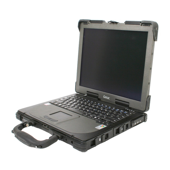
- Page 1 M230 Operation Manual Part Number: 7990011600010000 0000 0001 (August 2006)
- Page 2 TRADEMARKS All brand and product names are trademarks or registered trademarks of their respective companies. NOTE The information in this manual is subject to change without notice.
-
Page 3: Table Of Contents
Table of Contents Preface ..................vii Chapter 1 Getting Started .............1-1 Getting the Computer Running..........1-2 Unpacking ................1-2 Connecting to AC Power ...........1-2 Opening the Cover .............1-4 Powering the Computer .............1-5 Taking a Look at the Computer ..........1-6 Right-Side Components .............1-6 Left-Side Components ............1-7 Rear Components...............1-8 Front Components..............1-9... - Page 4 Windows Keys ..............2-6 Function Keys ..............2-6 Fn Key................2-7 Hot Keys ................2-7 Using the Touchpad ..............2-9 Configuring the Touchpad ..........2-11 Using the Touchscreen (Optional) .........2-12 Using the Hard Disk Drive ............2-14 Replacing the Hard Disk Drive ........2-14 Using the Optical Drive ............2-17 Installing the Optical Drive ..........2-18 Inserting and Removing a Disc ........2-20 Using the Video Features............2-22...
- Page 5 Power-Saving Tips ..............3-11 Chapter 4 Expanding Your Computer........4-1 Connecting an External Monitor ..........4-2 Connecting a USB Device ............4-3 Connecting a Parallel Device...........4-4 Connecting a Serial Device .............4-5 Connecting an IR Device............4-6 Connecting an IEEE 1394B Device ........4-8 Using PC Cards ...............4-9 PC Card Type..............4-9 CardBus Support..............4-9 Inserting and Removing a PC Card........4-9...
- Page 6 Location Guidelines ............7-4 General Guidelines.............7-4 Cleaning Guidelines ............7-5 Battery Pack Guidelines .............7-5 When Traveling ...............7-6 Chapter 8 Troubleshooting........... 8-1 Preliminary Checklist ..............8-2 Solving Common Problems .............8-3 Battery Problems..............8-4 Bluetooth Problems............8-4 Optical Drive Problems............8-5 Display Problems ...............8-6 Hardware Device Problems..........8-7 Hard Disk Drive Problems ..........8-7 Infrared Problems...............8-8 Keyboard, Mouse and Touchpad Problems .......8-8 LAN Problems ..............8-9...
- Page 7 USA and Canada Safety Requirements and Notices..B-6 European Union CE Marking and Compliance Notices ... B-9...
-
Page 9: Preface
Preface This manual contains information that will help you operate the computer. It is divided into 8 chapters and 2 appendices. Chapter 1, Getting Started, takes you through the process of setting up the computer and identifying its external components. Chapter 2, Operating Your Computer, tells you how to use the computer’s components and features. -
Page 10: Notational Conventions
Notational Conventions Throughout this manual, the following conventions are used to distinguish elements of text. NOTE: identifies additional information that requires special attention. CAUTION: identifies important information that, if not followed, may result in loss of data or damage to the computer. Keyboard keys are shown in a bold typeset. -
Page 11: Chapter 1 Getting Started
CHAPTER Getting Started Congratulations on purchasing this computer. This high performance notebook computer is especially designed for the practical applications of warehouses, automobiles, vehicles, public security, repairing, assisting the handicapped, and other demanding situations where conventional notebook computers just cannot measure This chapter first tells you step by step how to get the computer up and running. -
Page 12: Getting The Computer Running
Getting the Computer Running This section guides you through the procedures for getting the computer ready for operation. Unpacking After unpacking the shipping carton, you should find these standard items: Notebook computer Accessories: − AC adapter (100~240 VAC, 50/60 Hz) −... - Page 13 NOTE: Power Supply Cord: (optional) Detachable, minimum 1.5 m long. Listed, rated minimum 125 V, 7 A, having a 2/18 AWG, type SVT flexible cord. One end terminates with a parallel blade, molded-on, attachments plug with a 7 A, 125 V (NEMA 1-15P) configuration;...
-
Page 14: Opening The Cover
CAUTION: When you disconnect the AC adapter, disconnect from the electrical outlet first and then from the computer. A reverse procedure may damage the AC adapter or the computer. When unplugging the connector, always hold the plug head. Never pull on the cord. NOTE: When the AC adapter is connected, it also charges the battery pack. -
Page 15: Powering The Computer
Powering the Computer Turning On 1. Make sure the computer is connected to AC power. 2. Press the power button. 3. Each time the computer is turned on, it performs a Power-On Self Test (POST), and the operating system such as Windows should start. -
Page 16: Taking A Look At The Computer
Taking a Look at the Computer This section identifies the external components of the computer and briefly describes the function of each component. NOTE: Depending on the model you purchased, the appearance of your computer may not exactly be the same as those shown in this manual. Right-Side Components Component Description... -
Page 17: Left-Side Components
Left-Side Components Component Description See Also Accepts a compact disc (CD) for installing or P. 2-17 CD/Combo/ DVD Dual loading software, accessing data, and playing Drive music/video. Secondary You can purchase a secondary battery pack that P. 3-6 Battery Pack supplies power to your computer when external power is not connected. -
Page 18: Rear Components
Rear Components Component Description See Also Connects an IrDA-compliant device for wireless P. 4-7 IR Port data transfer. Connects the AC adapter. P. 1-3 Power Connector Serial Port Connects a serial device, such as an external P. 4-6 modem. Connects the telephone line. P. -
Page 19: Front Components
Front Components Component Description See Also Top Cover Locks the top cover. P. 1-4 Latch Kensington Locks the computer to a stationary object for P. 7-2 Lock security. Provides a convenient way to use the P. 2-12 Touchscreen Pen (option) touchscreen. - Page 20 Component Description See Also Device Show the current status of the computer’s Indicators devices. AC power indicator. P. 3-2 Glows green when the computer is using AC power. Glows red when the computer, using AC power, is in Standby mode. Battery Charge Indicator P.
-
Page 21: Bottom-Side Components
Bottom-Side Components Component Description See Also Sends out sound and voice from the computer. P. 2-20 Stereo Speaker Memory Slot Contains the memory slot for expanding the P. 4-12 memory size of your computer. Docking For connecting to a Port Replicator / car mount Connector (both are available as an option). - Page 22 Component Description See Also SIM Card Slot Contains the SIM card slot for using the GPS P. 2-26 function. 1-12 Getting Started...
-
Page 23: Top-Open Components
Top-open Components Component Description See Also Power Button Turns the computer power ON and OFF. P. 1-5 Getting Started 1-13... - Page 24 Component Description See Also Serves as the data input device of the computer. P. 2-4 Keyboard Touchpad Serves as the pointing device of the computer. P. 2-9 Device Show the current status of the computer’s Indicators devices. Power On Indicator P.
-
Page 25: Where To Go From Here
Where to Go from Here As your computer is ready for operation, you may want to do any of the following now: For this purpose… Do this… To know more about the computer… Go on to the next chapter. To install the operating system if your See the operating system manual. - Page 26 1-16 Getting Started...
-
Page 27: Chapter 2 Operating Your Computer
CHAPTER Operating Your Computer This chapter provides information about the use of the computer. If you are new to computers, reading this chapter will help you learn the operating basics. If you are already a computer user but are new to notebook computers, you may choose to read only the parts containing information unique to your computer. -
Page 28: Starting And Stopping The Computer
Starting and Stopping the Computer There are a number of ways to start and stop the computer. Starting the Computer You always start the computer using the power button. A computer starts up with an operating system (OS) existing on the storage device such as the hard disk;... - Page 29 To stop in Do this… To start up or this mode… resume again Depending on your settings in Windows, Hibernation Press the power you can place the computer in button. Hibernation mode by: • Closing the display cover • Pressing Fn+F10 •...
-
Page 30: Using The Keyboard
Using the Keyboard NOTE: Your computer features backlight for your keyboard to help you see the keyboard keys during poor lighting conditions. Press Fn+F1 to turn it on/off (see Hot Keys later in this chapter). Your keyboard has all the standard functions of a full-sized computer keyboard plus a key added for specific functions. -
Page 31: Cursor-Control Keys
Cursor-Control Keys NOTE: The word “cursor” refers to the indicator on the screen that lets you know exactly where on your screen anything you type will appear. It can take the form of a vertical or horizontal line, a block, or one of many other shapes. Numeric Keypad A 15-key numeric keypad is embedded in the typewriter keys as shown next:... -
Page 32: Euro Symbol
NOTE: When the numeric keypad is activated and you need to type the English letter in the keypad area, you can turn Num Lock off or you can press Fn and then the letter without turning Num Lock off. Some software may not be able to use the numeric keypad on the computer. If so, use the numeric keypad on an external keyboard instead. -
Page 33: Fn Key
Fn Key key, at the lower left corner of the keyboard, is used with another key to perform the alternative function of a key. The letter “Fn” and the alternative functions are identified by the color of blue on the keytop. To perform a desired function, first press and hold , then press the other key. - Page 34 Description Switches the display output to one of the following when an external device is connected. Upon booting the system with CRT: LCD & CRT NOTE: Fn+F9 will not work when playing a DVD/MPEG movie. Using the VGA utility’s “Graphics Properties” to switch the display output is not allowed.
-
Page 35: Using The Touchpad
Using the Touchpad CAUTION: Do not use a sharp object such as a pen on the touchpad. Doing so may damage the touchpad surface. NOTE: For optimal performance of the touchpad, keep your fingers and the pads clean and dry. When tapping on the pad, tap lightly. Do not use excessive force. The touchpad is a pointing device that allows you to communicate with the computer by controlling the location of the pointer on the screen and making selection with the buttons. - Page 36 Here are some common terms that you should know when using the touchpad: Term Action Point Move your finger on the pad until the cursor points to the selection on the screen. Click Press and release the left button. –or– Tap gently anywhere on the pad.
-
Page 37: Configuring The Touchpad
Configuring the Touchpad You may want to configure the touchpad to suit your needs. For example, if you are a left-handed user, you can swap the two buttons so that you can use the right button as the left button and vise versa. You can also change the size of the on-screen pointer, the speed of the pointer, and so To configure the touchpad, you can use the standard Microsoft or IBM PS/2 driver if you are using Windows. -
Page 38: Using The Touchscreen (Optional)
Using the Touchscreen (Optional) NOTE: Make sure the “Serial Port COM3 (Touchscreen)” item is set properly in the SCU program. (See “Advanced Menu” in chapter 5 for information.) CAUTION: Do not use a sharp object such as a ballpoint pen or pencil on the touchscreen. - Page 39 Here are some common terms that you should know when using the touchscreen: Term Action Click/Point Tap gently on the touchscreen. Double-click Tap twice on the touchscreen rapidly. Drag and Press lightly on the touchscreen and move your finger drop until you reach your destination (drag).
-
Page 40: Using The Hard Disk Drive
Using the Hard Disk Drive Your computer comes with a removable hard disk drive as drive C. A hard disk drive is a storage device with non-removable, rotating, magnetic storage platters inside it. It is where your operating system and application software programs are stored. - Page 41 7. Open the hard disk drive slot cover by pressing on both sides of the release latch using your thumb and index fingers. 8. Pull on the ribbon film to remove the hard disk drive compartment. 9. Remove the three front and two rear screws securing the hard disk drive to the compartment and remove the compartment cover.
- Page 42 10. Place the new hard disk drive into the compartment and tighten the three front and two rear screws. 11. Slide the HDD compartment into the slot until it reaches the end. 12. Close the hard disk drive slot cover to secure the HDD compartment. 2-16 Operating Your Computer...
-
Page 43: Using The Optical Drive
Using the Optical Drive Depending on the model, your computer comes with a CD, Combo drive, or DVD dual recorder located on the left side of the computer. This drive is usually configured as drive D. The drive uses removable 5.25-inch silver discs, which look like standard music discs. -
Page 44: Installing The Optical Drive
NOTE: For Combo/DVD Dual drive only. This product incorporates copyright protection technology that is protected by method claims of certain U.S. patents and other intellectual property rights owned by Macrovision Corporation and other rights owners. Use of this copyright protection technology must be authorized by Macrovision Corporation, and is intended for home and other limited viewing uses only unless otherwise authorized by Macrovision Corporation. - Page 45 5. Close the optical drive bay cover to secure the drive in place. If another module is inside the drive bay 4. Check to see if any other module is installed in the optical drive bay. If no other module is inside, proceed directly to step 10. 5.
-
Page 46: Inserting And Removing A Disc
10. Insert the optical drive into the drive bay ( ) and return the release knob ( ). 11. Close the optical drive bay cover to secure the drive in place. Inserting and Removing a Disc Follow this procedure to insert or remove a disc. 1. - Page 47 5. To insert a disc, place down the disc in the tray with its label facing up. Slightly press the center of the disc until it clicks into place. To remove a disc, hold the disc by its outer edge and lift it up from the tray.
-
Page 48: Using The Video Features
Using the Video Features The video subsystem of your computer features: 14.1-inch TFT (Thin-Film Transistor) color LCD display with 1024 768 XGA (Extended Video Graphics Array) resolution, or × 15-inch TFT color LCD display with 1400 1050 SXGA+ (Super × Extended Video Graphics Array) resolution. - Page 49 Your computer has been set to a default resolution and number of colors before shipment. You can view and change display settings through your operating system. See your operating system documentation or online help for specific information. For displaying in higher resolutions, you can connect an external CRT monitor that supports higher resolutions.
-
Page 50: Using The Audio Features
Using the Audio Features NOTE: To take advantage of the enhanced audio capabilities, the device driver supplied with your computer must be installed (see chapter 6 for details). If you experience interference while recording, try lowering the microphone recording volume. The audio subsystem of your computer features: External audio connectors ( ) on the rear, and A set of speakers ( ) on the bottom side... -
Page 51: Connecting Audio Devices
Connecting Audio Devices For higher audio quality, you can send or receive sound through external audio devices. NOTE: After connecting an external audio device, make sure that you specify the use of the correct audio device in Windows. Audio Output Connector ( ) can be connected to the line-in connector of powered speakers with built-in amplifiers, headphones, or earphone set. -
Page 52: Using The Communication Features
Using the Communication Features Using the LAN NOTE: To take advantage of the LAN (Local Area Network) feature, the device driver supplied with your computer must be installed (see chapter 6 for details). The internal 10/100/1000Base-T Ethernet module allows you to connect your computer to a network. -
Page 53: Using The Wireless Lan (Wlan)
Using the Wireless LAN (WLAN) An internal Mini PCI wireless LAN module have been pre-installed by your computer manufacturer at the factory. This allows you to access corporate networks or the Internet in a wireless environment. The WLAN features include: Peer-to-Peer (Ad-Hoc) and Access Point (Infrastructure) modes support WEP (Wired Equivalent Privacy) 64/128-bit data encryption... -
Page 54: Connecting To A Wireless Network
3. Click Network Connections, then double-click the Wireless Network Connection icon 4. Click Properties in the Wireless Network Connection Status dialog box. 5. You can configure your WLAN settings in the Wireless Network Connection Properties dialog box. Turning Off/On the WLAN Radio NOTE: The FAA (Federal Aviation Agency) has deemed it unsafe to operate wireless devices in aircraft as this may interfere with flight safety. - Page 55 4. If any wireless network is detected, the following window appears on screen. 5. Click to select a wireless network to connect to, and then click Connect. 6. Depending on the settings, you may be asked to enter a wireless security password (encryption key).
-
Page 56: Using The Modem
Using the Modem NOTE: To take advantage of the modem feature, the device driver supplied with your computer must be installed (see chapter 6 for details). The internal 56 K fax/data modem allows you to use the telephone line to communicate with others by fax, email, or connect to an online service or bulletin board. -
Page 57: Using The Gps (Optional)
Connecting Using GPRS Your computer can receive General Packet Radio Services (GPRS), a high-speed data-only service that transmits data over a mobile telephone network. In addition, GPRS provides permanent on-line connection. To use GPRS, you must have a subscription to the function with a service provider that supports GPRS. -
Page 58: Connecting To Another Bluetooth Device
The status of the Bluetooth connection is indicated by the Bluetooth icon located in the system tray in the lower-right part of the screen. Status Icon (blue with white logo) Connected (blue with green logo) You can use the Bluetooth Utility to configure Bluetooth connection settings and transfer files. - Page 59 3. The Add New Connection Wizard window appears. Select Express Mode (Recommended), then click on Next. 4. Select the device to connect to and click on Next. 5. Depending on the type of Bluetooth device that you want to connect to, you will need to enter the pertinent information.
- Page 60 Sending a File icon, and then click Wireless File Transfer. The 1. Right-click the following screen appears. 2. In the Wireless File Transfer window, click Add to browse for the file to send. The file(s) will show on the File/Folder window. 3.
- Page 61 For detailed information on using the Bluetooth Utility, see the Bluetooth Utility Help on your computer by clicking on Help, then Help . . . 2-36 Operating Your Computer...
- Page 62 HELP FOR ModuleSW PROGRAM Version: ModuleSW 1.0.1.9 The ModuleSW program can to set BlueTooth/WirelessLan/3G modules power ON or OFF and keep the state to system startup. There are 5 subitem can be selection. The menu and subitem as follow: The user can select and click BlueTooth or WirelessLan(WLAN) or 3G subitem to switch module power state.
- Page 63 If user select and click "3G OFF" subitem . ModuleSW will switch 3G module power OFF state to ON and When system startup(or restart) ,ModuleSW will keep 3G module to power ON state. If user move cursor to ModuleSW tray-icon than show BuleTooth/WirelessLan/3G module power state.
-
Page 64: Chapter 3 Managing Power
CHAPTER Managing Power Your computer operates either on external AC power or internal battery power. This chapter tells you how you can effectively manage power. To maintain optimal battery performance, it is important that you use the battery in the proper way. The topics in this chapter include: What is an AC adapter How to charge the battery pack... -
Page 65: Ac Adapter
AC Adapter CAUTION: The AC adapter is designed for use with your computer only. Connecting the AC adapter to another device can damage the adapter. The AC power cord supplied with your computer is for use in the country where you purchased your computer. -
Page 66: Battery Pack
Battery Pack The battery pack is the internal power source for the computer. It is rechargeable using the AC adapter. The operating time of a fully charged battery pack depends on how you are using the computer. When your applications often access peripherals, you will experience a shorter operating time. -
Page 67: Initializing The Battery Pack
NOTE: The battery level may automatically lessen due to the self-discharge process (0.21 % per day), even when the battery pack is fully charged (100 %). This happens no matter if the battery pack is installed in the computer. Initializing the Battery Pack You need to initialize a new battery pack before using it for the first time or when the actual operating time of a battery pack is much less than expected. -
Page 68: Replacing The Primary Battery Pack
Replacing the Primary Battery Pack CAUTION: There is danger of explosion if the battery is incorrectly replaced. Replace the battery only with the computer manufacturer’s optional battery packs. Discard used batteries according to the dealer’s instructions. Do not attempt to disassemble the battery pack. To replace the primary battery pack, follow these steps: 1. -
Page 69: Installing The Secondary Battery Pack
5. Slide the new battery pack all the way into the slot. Make sure to observe the correct orientation (the ribbon strip must face outward for future battery back removal). 6. Close the slot cover to secure the battery pack. Installing the Secondary Battery Pack If you often rely on battery power for a long period of time while traveling, you may consider the purchase of an additional battery pack... -
Page 70: Battery Low Signals And Actions
6. The optical drive will slide out partially. Gently pull on it to remove 7. Slide the secondary battery pack all the way into the slot. Make sure to observe the correct orientation (the ribbon strip must face outward for future battery pack removal). 8. - Page 71 Always respond to Battery Low by placing your computer on Standby or Hibernation mode, turning off the computer, or connecting the AC adapter. If you do not take any action, the computer will automatically hibernate and turn off. CAUTION: If you are using a flash PC card, do not access the card during battery low periods. This is because the access may take longer than the time it takes the battery to run out of charge, thus making your access to the card unsuccessful.
-
Page 72: Power Management
Power Management Your computer supports ACPI (Advanced Configuration and Power Interface) for power management. The power management feature allows you to reduce the power consumption for energy saving. With an ACPI-compliant operating system such as Windows 2000 and Windows XP, power supply to different computer components is controlled on an as-needed basis. -
Page 73: Hibernation
Hibernation Hibernation is a very useful feature. People frequently open many applications when they use computers. It takes some time to get all these applications open and running, and normally they all have to be closed before the system can be turned off. When you use the hibernation feature, you do not have to close the applications. -
Page 74: Power-Saving Tips
Power-Saving Tips In addition to your computer’s automatic power management, you can do your part to maximize the battery’s operating time by following these suggestions. Do not disable Power Management. Decrease the LCD brightness to the lowest comfortable level. Disable the parallel and serial ports if no devices are connected to these ports. - Page 75 3-12 Managing Power...
-
Page 76: Chapter 4 Expanding Your Computer
CHAPTER Expanding Your Computer You can expand the capabilities of your computer by connecting other peripheral devices. When using a device, be sure to read the instructions accompanying the device together with the relevant section in this chapter. This chapter gives guidelines on installing and using these devices: External monitor USB device Parallel device... -
Page 77: Connecting An External Monitor
Connecting an External Monitor If you want the benefits of a larger display screen with higher resolution, you can connect an external CRT monitor to your computer. Follow this procedure to connect an external monitor: 1. Make sure that the computer is not turned on. 2. -
Page 78: Connecting A Usb Device
Connecting a USB Device Your computer has two USB ports that supports transfer rates up to 12 MB/s for USB 1.1 devices and 480 MB/s for USB 2.0 devices, such as digital camera, scanner, printer, modem, and mouse. USB is specified to be an industry standard extension to the PC architecture. -
Page 79: Connecting A Parallel Device
Connecting a Parallel Device Your computer has a parallel port for connecting a parallel device such as printer. The port supports ECP (Extended Capabilities Port) and EPP (Enhanced Parallel Port) modes that turn the standard parallel port into a high-speed bi-directional peripheral port. Follow this procedure to connect a parallel device: 1. -
Page 80: Connecting A Serial Device
Connecting a Serial Device Your computer has a serial port for connecting a serial device such as an external modem. Follow this procedure to connect a serial device: 1. Make sure the “Serial Port COM1” item is set properly in the SCU program. -
Page 81: Connecting An Ir Device
Connecting an IR Device Your computer has an IR (infrared) port for connecting an infrared-equipped device wirelessly such as another computer, printer, or PDA (Personal Digital Assistant). Follow this procedure to connect an IR device: 1. Make sure that the “Serial Port COM2 (FIR)” item is set properly in the SCU program. - Page 82 NOTE: During infrared communication, take note of the following: Do not move the computer and IR device. Do not enter Standby mode. Do not use a cell phone or another IR device near the computer. Avoid strong light such as sunlight or fluorescent light. Disable the screen saver.
-
Page 83: Connecting An Ieee 1394B Device
Connecting an IEEE 1394B Device NOTE: Your IEEE 1394B port will only function under Windows XP SP2. It is also Windows Vista ready. Make sure that the 1394B driver is installed correctly (see chapter 6 for details). To connect an IEEE 1394A (also known as FireWire 400) device to the computer’s IEEE 1394B (also known as FireWire 800) port, you need an optional FireWire 800/FireWire 400 bilingual cable. -
Page 84: Using Pc Cards
Using PC Cards Your computer has a PC card slot. PC cards are credit card-sized peripheral products based on the standards developed by PCMCIA (Personal Computer Memory Card International Association). PCMCIA is a non-profit association for promoting the interchangeability among mobile computers where ruggedness, low power, and small size are critical. - Page 85 2. Open the PC card slot cover by pressing on both sides of the release latch using your thumb and index fingers. 3. Slide the PC card, with its label facing up, into the slot until the eject button pops out. Eject Button 4.
-
Page 86: System Memory Upgrade
System Memory Upgrade You can upgrade your computer by changing system memory to a maximum of 2 GB on the two 200-pin 400/533 MHz DDR2 SO-DIMM slots. To install the SO-DIMM: 1. Carefully place the notebook computer upside down. 2. Remove the nine screws to detach the SO-DIMM compartment cover. - Page 87 3. To install the SO-DIMM, match the SO-DIMM's notched part with the socket's projected part and firmly insert the SO-DIMM into the socket at a 20-degree angle. Then push down until the retaining clips lock the SO-DIMM into position. 4. Replace the SO-DIMM compartment cover and secure with nine screws.
-
Page 88: Chapter 5 Setup Configuration Utility (Scu)
CHAPTER Setup Configuration Utility (SCU) SCU is a program for configuring the BIOS (Basic Input/Output System) settings of the computer. BIOS is a layer of software, called firmware, that translates instructions from other layers of software into instructions that the computer hardware can understand. -
Page 89: When And How To Use The Scu Program
When and How to Use the SCU Program When to Use You need to run the SCU program when: You see an error message on the screen requesting you to run Setup. You want to restore the factory default settings. You want to modify some specific settings according to the hardware. - Page 90 The SCU menu can be divided into four areas: On the top is the menu bar containing the titles of the available menus. Each menu title brings a specific menu. The center column of the menu displays the current configuration information of the system, devices, and memory items.
-
Page 91: Moving Around And Making Selections
Moving Around and Making Selections In most cases, you must go through two levels to complete the setting for an item: menu title and submenu. Use the keyboard to move around and make selections. A brief description of keyboard usage is listed next: Function ←... -
Page 92: Main Menu
Main Menu The Main menu contains the system date and time as well as the IDE interface setting of the system. System Time sets the system time. System Date sets the system date. IDE Channel 0/1 Master sets the type of storage device installed. The options are User, Auto, CD-ROM, ATAPI Removable, None, IDE Removable, and Other ATAPI. -
Page 93: Advanced Menu
Advanced Menu The Advanced menu contains the I/O (input/output) configuration settings of the system. Serial Port COM1 enables or disables the serial (COM1) port. The options are Enabled and Disabled. Serial Port COM2 (FIR) enables or disables the infrared (COM2) port. The options are Enabled and Disabled. - Page 94 Falling Time to Park HDD sets the time (millisecond) for EC to inform SMI to park the HDD during an accidental drop. The options are 0 (disabled) to 127. Free Drop Status specifies if the computer had been free-dropped. The options are Yes and No.
-
Page 95: Boot Menu
Boot Menu The Boot menu sets the sequence of the devices to be searched for the operating system. The bootable devices will be automatically detected during POST and shown here, allowing you to set the sequence that the BIOS uses to look for a boot device from which to load the operating system. -
Page 96: Exit Menu
Exit Menu The Exit menu displays ways of exiting the SCU program. After finishing with your settings, you must save and exit so that the changes can take effect. Exit Saving Changes saves the changes you have made and exits BIOS Setup Utility. - Page 97 5-10 Setup Configuration Utility (SCU)
-
Page 98: Chapter 6 Installing Software Drivers
CHAPTER Installing Software Drivers To take full advantage of the unique features of your computer, some operating systems require custom software, known as drivers, to be installed. If you purchased the computer with Windows pre-installed, your dealer may have already installed the drivers. If not, you need to install the drivers using the driver disc supplied with your computer. -
Page 99: How To Use The Driver Cd
How to Use the Driver CD NOTE: • The drivers may have been updated after this manual was published. For driver upgrade, please contact your dealer. • You can always find README or document files on the driver disc. These files contain the latest information from the software supplier. -
Page 100: Drivers On The First Page
The main screen appears as shown next: To install the necessary driver, just click on the particular option and follow the onscreen instructions to continue and complete installation. Drivers on the First Page Device Driver Ensures the full function of the following drivers. Install this main driver before installing the other drivers. - Page 101 Allows you to use the TPM (Trusted Platform Module) support for security. Bluetooth Allows your computer to connect to Bluetooth-compliant devices. TouchScreen Allows you to use your fingers (or optional touchscreen pen) as a pointing device on the LCD screen (refer to the next section for further instructions).
-
Page 102: Drivers On The Second Page
Drivers on the Second Page Upon clicking on Next Page, the following screen appears. Installing Software Drivers... - Page 103 Vehicle Dock Upon clicking on this, the following screen appears. Video Capture Allows you to connect a video capture device through the AV input port (option). USB-to-COM Allows you to use the optional wireless modem and GPS features to transmit information wirelessly. Dual Core Installs the dual core hotfix for Windows XP only.
- Page 104 NOTE: The OSD utility is an option for you. You can decide whether you would like to have this utility installed. (See the next section for details.) BT Calibration Installs the battery pack automatic calibration utility. NOTE: For Windows 2000 only. Install the DirectX 8.1 driver to take full advantage of multimedia applications.
-
Page 105: Touchscreen Driver
Touchscreen Driver To install the touch screen driver, perform the following: 1. Insert the driver disc into the optical drive. 2. Click on TouchScreen and follow the onscreen instructions to continue. 3. When finished installing, select Yes to reboot your system. The driver should now be loaded. -
Page 106: Using The Osd
Using the OSD NOTE: The OSD utility is an option for you. You can decide whether you would like to have this utility installed. With the OSD utility installed, the utility will be activated and an icon will appear on the system tray every time Windows starts up. A graphic display will appear on the screen to indicate the current status of certain operations (as listed next). - Page 107 Icon OSD Description Hot Key/Button Operation Icon appears on the screen to indicate that wireless LAN is on or off. The OSD disappears after a few seconds. Fn+F11 Fn+F11 Icon appears on the screen to indicate that AC power cord has been connected or unplugged. The OSD disappears after a few seconds.
-
Page 108: Chapter 7 Caring For The Computer
CHAPTER Caring for the Computer Taking good care of your computer will ensure a trouble-free operation and reduce the risk of damage to your computer. This chapter gives you guidelines covering these areas of maintenance: How to protect the computer What to note when using and storing the computer How to clean the computer What to note when using the battery pack... -
Page 109: Protecting The Computer
Protecting the Computer To safeguard the integrity of your computer data as well as the computer itself, you can protect the computer in several ways as described in this section. Using the Password The power-on password protects your computer against unauthorized use. -
Page 110: Using An Anti-Virus Strategy
Using an Anti-Virus Strategy New viruses are always being developed nowadays and they are attacking computers even more easily with emails so commonly used worldwide. You can also install a virus-detecting program to monitor potential viruses that could damage your files. Caring for the Computer... -
Page 111: Taking Care Of The Computer
Taking Care of the Computer Location Guidelines Use the computer where the temperature is between 0 °C (32 °F) and 55 °C (131 °F). Avoid placing the computer in a location subject to high humidity, extreme temperatures, mechanical vibration, direct sunlight, or heavy dust. -
Page 112: Cleaning Guidelines
Cleaning Guidelines Never clean the computer with its power on. Use a soft cloth moistened with water or a non-alkaline detergent to wipe the exterior of the computer. Gently wipe the display with a soft, lint-free cloth. Do not use alcohol or detergent on the display. -
Page 113: When Traveling
When Traveling Before traveling with your computer, make a backup of your hard disk data into USB disks or other storage devices. As an added precaution, bring along an extra copy of your important data. Make sure the battery pack is fully charged. Make sure the computer is turned off. -
Page 114: Chapter 8 Troubleshooting
CHAPTER Troubleshooting Hardware, software, or a combination of both can cause computer problems. When you encounter any problem, it might be a typical problem that can easily be solved. This chapter tells you what actions to take when solving common computer problems. -
Page 115: Preliminary Checklist
Preliminary Checklist Here are helpful hints to follow before you take further actions when you encounter any problem: Try to isolate which part of the computer is causing the problem. Make sure that you turn on all peripheral devices before turning on the computer. -
Page 116: Solving Common Problems
Solving Common Problems For easy reference, the problems are divided into these categories. Problem Type Go to Battery Problems P. 8-4 Bluetooth Problems P. 8-4 Optical Drive Problems P. 8-4 Display Problems P. 8-5 Hardware Device Problems P. 8-7 Hard Disk Drive Problems P. -
Page 117: Battery Problems
Battery Problems The battery does not charge (Battery Charge indicator does not light amber). Make sure that the AC adapter is properly connected. Make sure that the battery is not too hot. Allow time for the battery pack to return to room temperature. Make sure that the battery pack is installed correctly. -
Page 118: Optical Drive Problems
I cannot end a Bluetooth connection. If another device is connected to your computer, you can either end the connection using the other device or by deactivating Bluetooth. Optical Drive Problems The optical drive cannot read a disc. Make sure that the disc is correctly seated in the tray, with the label facing up. -
Page 119: Display Problems
Display Problems Nothing appears on the screen. If the power-on indicator is not on, check the electrical outlet, the plugs and power cords. If the power button does not respond to a light touch, press the button firmly. If you are using battery power, make sure that it has a charge remaining and that it is installed correctly. -
Page 120: Hardware Device Problems
Make sure that the monitor’s signal cable is properly connected. Switch the display to the monitor by pressing or change the display through the settings in Display Properties. Simultaneous display/multi-display does not work. Make sure that you turn on the external monitor before turning on the computer. -
Page 121: Infrared Problems
The hard disk drive in-use indicator glows without blinking. The data files stored on the hard disk drive may be fragmented. Use a tool such as Window’s Disk Defragmenter to defragment the files. Infrared Problems The IR port does not work. Make sure that the IR ports of the two device face each other within a ±15-degrees angle and 1 meter (3 feet) distance and there are no obstructions in between. -
Page 122: Lan Problems
The external keyboard does not work. Make sure that the keyboard cable is properly connected. The USB mouse does not work. Make sure that the mouse cable is properly connected. The touchpad does not work, or the pointer is difficult to control with the touchpad. - Page 123 Radio interference exists. Move your computer away from the device causing the radio interference such as microwave oven and large metal objects. Plug your computer into an outlet on a different branch circuit from that used by the affecting device. Consult your dealer or an experienced radio technician for help.
-
Page 124: Modem Problems
Make sure that the user name or password is correct. You have moved out of range of the network. Turn off power management. Modem Problems The modem does not work. Make sure that the device driver is correctly installed. Make sure that the COM port in the communication software is correctly set. -
Page 125: Printer Problems
The computer does not enter Standby or Hibernation mode immediately. If the computer is performing an operation, it normally waits for the operation to finish. The computer does not resume from Standby or Hibernation mode. The computer automatically enters Standby or Hibernation mode when the battery pack is empty. -
Page 126: Software Problems
Software Problems An application program does not work correctly. Make sure that the software is correctly installed. If an error message appears on the screen, consult the software program’s documentation for further information. If you are sure the operation has stop, reset the computer. (See “Resetting the Computer”... -
Page 127: Startup Problems
Startup Problems When you turn on the computer, it does not respond and the Power Indicator does not light green. If you are using an external AC power, make sure that the AC adapter is correctly and securely connected. If so, make sure that the electrical outlet works properly. -
Page 128: Other Problems
Other Problems The date/time is incorrect. Correct the date and time via the operating system or SCU program. After you have performed everything as described above and still have the incorrect date and time every time you turn on the computer, the RTC (Real-Time Clock) battery is at the end of its life. -
Page 129: Resetting The Computer
Resetting the Computer You may have to reset (reboot) your computer on some occasions when an error occurs and the program you are using hangs up. If the system operation seems to hang up, first wait. It is possible that the system is processing data. -
Page 130: Appendix A Specifications
APPENDIX Specifications Specifications NOTE: Specifications are subject to change without any prior notices. NOTE: Specifications are subject to change without any prior notices. Parts Specifications Intel Yonah low voltage dual core processor µ-FCBGA package 1.66 GHz Intel Yonah low voltage dual core processor µ-FCBGA package 1.5 GHz 667 MHz Front Side Bus (FSB), 15 W thermal ceiling Core logic Intel 945GM chipset (Calistoga) + ICH7-M (PCI express ×... - Page 131 Parts Specifications Storage device Hard disk SATA, easily removable for maintenance, drive bay optional built-in heater for low temperature support (–20 C~55 optional low temperature 20 GB without heater Built-in protection to support free drop from 0 to 3 feet in operating mode: 1~3 feet drop protected by G-sensor 0~1 foot drop protected by special resistant-designed construction Optical...
- Page 132 Parts Specifications 0 °C (32 °F) to 55 °C (131 °F) – standard Environment Temperature Operating: –20 °C (–4 °F) to 60 °C (140 °F) – option –40 °C (–40 °F) to 70 °C (158 °F) Storage: Humidity Operating: 5 % to 95 % RH, non-condensing Altitude Operating: 15,000 ft...
- Page 133 Specifications...
-
Page 134: Appendix B Regulatory Information
APPENDIX Regulatory Information This appendix provides regulatory statements and safety notices on your computer. NOTE: Marking labels located on the exterior of your computer indicate the regulations that your model complies with. Please check the marking labels and refer to the corresponding statements in this appendix. -
Page 135: On The Use Of The System
On the Use of the System Class B Regulations Federal Communications Commission Radio Frequency Interference Statement NOTE: This equipment has been tested and found to comply with the limits for a Class B digital device pursuant to Part 15 of the FCC Rules. These limits are designed to provide reasonable protection against harmful interference in a residential installation. -
Page 136: Safety Notices
Canada Canadian Department of Communications Radio Interference Regulations Class B Compliance Notice This Class B digital apparatus meets all requirements of the Canada Interference-Causing equipment regulations. Cet appareil numérique de Classe B respecte toutes les exigences du Règlement Canadien sur le matériel brouileur. This digital apparatus does not exceed the Class B limits for radio noise emissions from digital apparatus set out in the Radio Interference Regulations of the Canadian Department of Communications. - Page 137 ENGLISH CAUTION: Danger of explosion if battery is incorrectly replaced. Replace only with the same or equivalent type recommended by the equipment manufacturer. Discard used batteries according to manufacturer's instructions. DEUTSCH VORSICHT: Explosionsgefahr bei unsachgemäßem Austausch der Batterie. Ersatz nur durch denselben oder einen vom Hersteller empfohlenen gleich-wertigen Typ.
-
Page 138: About The Modem
About the Modem Caution Never install telephone wiring during a lightning storm. Never install telephone jacks in wet locations unless the jack is specifically designed for wet locations. Never touch non-insulated telephone wires or terminals unless the telephone line has been disconnected at the network interface. Use caution when installing or modifying telephone lines. -
Page 139: On The Use Of Rf Device
On the Use of RF Device NOTE: The information in this section applies to models with the wireless LAN module. USA and Canada Safety Requirements and Notices IMPORTANT NOTE: To comply with FCC RF exposure compliance requirements, the antenna used for the transmitters (WLAN and Bluetooth) must be installed to provide a separation distance of at least 20 cm from all persons and must not be co-located or operating in conjunction with any other antenna or transmitter. - Page 140 The use of wireless devices in hospitals is restricted to the limits set forth by each hospital. Antenna use: In order to comply with FCC RF exposure limits, low gain integrated antennas for the transmitters (WLAN and Bluetooth) should be located at a minimum distance of 20 cm (8 inches) or more from the body of all persons.
- Page 141 EMC Requirements This device uses, generates and radiates radio frequency energy. The radio frequency energy produced by this device is well below the maximum exposure allowed by the Federal Communications Commission (FCC). This device complies with the limits for a Class B digital device pursuant to Part 15 subpart C of the FCC Rules and Regulations.
-
Page 142: European Union Ce Marking And Compliance Notices
Canada Radio Frequency Interference Requirements To prevent radio interference to the licensed service, this device is intended to be operated indoors and away from windows to provide maximum shielding. Equipment (or its transmit antenna) that is installed outdoors is subject to licensing. Pour empêcher que cet appareil cause du brouillage au service faisant l'objet d'une licence, il doit être utilisé... - Page 143 Greek To προϊόν αυτό πληροί τις προβλέψεις της Ευρωπαϊκής Οδηγίας 1999/5/EC. Icelandic Þessi vara stenst reglugerð Evrópska Efnahags Bandalagsins númer 1999/5/EC. Italian Questo prodotto è conforme alla Direttiva Europea 1999/5/EC. Norwegian Dette produktet er i henhold til bestemmelsene i det europeiske direktivet 1999/5/EC.
- Page 144 General European standards dictate maximum radiated transmit power of 100 mW Effective Isotropic Radiated Power (EIRP) and the frequency range 2400 – 2483.5 MHz. Belgium and the Netherlands In Belgium and the Netherlands, the product may not be used outdoors. See the instructions next under the heading “How to Turn Off the Wireless LAN Radio.”...
- Page 145 Departments in Which the Wireless LAN Module’s Maximum EIRP Not Shown in the Previous Table Frequency Ranges (MHz) Indoors Outdoors 2400 – 2446.5 10 mW Not permitted 2446.5 – 2483.5 100 mW 100 mW on private property with Ministry of Defense approval Turning Off the Wireless LAN Radio NOTE: Turning the wireless LAN radio off is not the same as disabling the wireless LAN card.
Need help?
Do you have a question about the M230 and is the answer not in the manual?
Questions and answers