
Subscribe to Our Youtube Channel
Related Manuals for Icom IC-T10


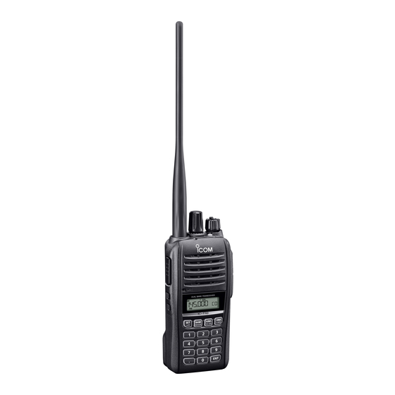
Summary of Contents for Icom IC-T10
- Page 1 BASIC MANUAL VHF/UHF DUAL BAND TRANSCEIVER |T10 This device complies with part 15 of the FCC Rules. Operation is subject to the condition that this device does not cause harmful interference.
-
Page 2: Features
Thank you for choosing this Icom product. This product is designed and built with Icom’ s state of the art technology and craftsmanship. With proper care, this product should provide you with years of trouble-free operation. ■ Important READ ALL INSTRUCTIONS carefully and completely before using the transceiver. -
Page 3: Precautions
This could cause an explosion and death. CAUTION: DO NOT short the terminals of R DANGER! NEVER use or charge Icom the battery pack. Shorting may occur if the battery packs with non-Icom transceivers terminals touch metal objects such as a or non-Icom chargers. -
Page 4: Battery Cautions
If the pack gets wet, be sure to wipe it dry may rupture or catch fire. cloth before using. CAUTION: DO NOT use the battery if it emits an abnormal odor, heats up, or is discolored or deformed. If any of these conditions occur, contact your Icom dealer or distributor. - Page 5 CAUTION: DO NOT charge the battery • The pack has been repeatedly charged. pack outside of the specified temperature range: 10˚C ~ 40˚C (50˚F ~ 104˚F). Icom The battery cells may deteriorate and recommends charging the pack at 25˚C swell due to their characteristics if used in (77˚F).
-
Page 6: Fcc Information
■ Trademarks the following measures: • Reorient or relocate the receiving Icom, Icom Inc. and the Icom logo are antenna. registered trademarks of Icom Incorporated • Increase the separation between the (Japan) in Japan, the United States, the United equipment and receiver. -
Page 7: Table Of Contents
■ Table of contents ■ Important ......... i SCAN OPERATION ������������������������� 17 ■ Features .......... i ■ Using the Scan function ....17 ■ Explicit definitions......i ■ Using the Priority Scan function ... 17 ■ Supplied accessories ...... i ■... -
Page 8: Panel Description
PANEL DESCRIPTION ■ Front, top, and side panels Speaker Function Microphone display 1 PTT SWITCH [PTT] (p� 11) 7 SET MODE • LOCK KEY [SET]/[ z Push to enter the Set mode. (p. 13) Hold down to transmit, release to z Hold down to turn the Lock function receive. - Page 9 PANEL DESCRIPTION 12 VOLUME • POWER KNOB [VOL] (p� 6) z Rotate to turn the transceiver ON or OFF. z Rotate to adjust the audio output level. 13 CONTROL DIAL [DIAL] z In the VFO mode, rotate to select an operating frequency. (p. 10) z In the Memory mode, rotate to select a Memory channel.
-
Page 10: Function Display
PANEL DESCRIPTION ■ Function display 1 2 4 5 6 1 BATTERY ICON (p� 5) 8 MEMORY ICON (p� 8) Displays the current capacity of the Displayed when the Memory mode is attached battery pack. selected. 2 DUPLEX ICON 9 MEMORY CHANNEL NUMBER •... -
Page 11: Preparation
PREPARATION ■ Attaching the battery pack Attach or detach the battery pack, as illustrated below. To attach: Slide the battery pack in the direction of the arrow. (1) Latch Push the battery pack until the latches make a ‘click’ sound. (2) To detach: Push latches in the direction of the arrow. -
Page 12: Charging The Battery Pack
PREPARATION ■ Charging the battery pack Prior to using the transceiver for the first time, the battery pack must be fully charged for optimum life and operation. NOTE: BE SURE to turn OFF the transceiver while charging with the supplied battery charger. -
Page 13: Belt Clip
■ Turning ON the transceiver z Rotate [VOL] clockwise to turn ON the transceiver. • A beep sounds. • “Icom” and the voltage are displayed, and then the operating frequency is displayed. L Rotate [VOL] fully counter-clockwise to turn OFF the transceiver. -
Page 14: Basic Operation
BASIC OPERATION ■ Receiving The following are basic settings for receiving. • Adjusting the squelch level (p. 9) • Selecting the Frequency selecting mode (p. 10) • Selecting the operating band (p. 11) • Selecting the operating mode (p. 11) •... -
Page 15: Selecting The Frequency Selecting Mode
BASIC OPERATION ■ Selecting the Frequency selecting mode The transceiver has Frequency selecting modes, as shown below. Repeatedly push [V/M/C] to select the selecting mode, as shown to the right. Rotate [DIAL] to select a frequency or channel. L In Call Channel mode, repeatedly push [BAND] to select a Call Channel. -
Page 16: Selecting The Operating Band
BASIC OPERATION ■ Selecting the operating band Select the operating band in the VFO mode, as shown below. Repeatedly push [V/M/C] to select the VFO mode. • The selected frequency is displayed. Repeatedly push [BAND] to select the operating band, as shown below. FM radio ■... -
Page 17: Setting A Frequency
BASIC OPERATION ■ Setting a frequency D Selecting a tuning step When you select the frequency by rotating [DIAL] in the VFO mode, it changes in the selected tuning step. Hold down [P] to enter the Tuning Step item of the Set mode. -
Page 18: Transmitting
BASIC OPERATION ■ Transmitting D Making a simplex call R WARNING! NEVER transmit for long periods of time. During prolonged transmissions at high power or mid-power, the transceiver radiates heat to protect itself from overheating. The transceiver’s chassis will become hot and may cause a burn. To prevent the transceiver’s overheating, the default setting of the time-out timer function is set to 5 minutes. -
Page 19: Using The Lock Function
BASIC OPERATION D About the transmit power levels Lower output power during short-range communications may reduce the possibility of interference to other stations. • When the BP-280 is attached: Approximately 5 W (High) /2.5 W (Mid) /0.5 W (Low) High ■... -
Page 20: Set Mode
SET MODE ■ Using the Set mode You can use the Set mode to set infrequently changed values or function settings. The transceiver has two types of Set modes, as shown below. D Using the Basic Set mode Example: Selecting a 20 kHz tuning step Push [SET] to enter the Set mode. -
Page 21: Set Mode Items
SET MODE ■ Set mode items D Initial Set mode D Set mode ITEM FUNCTION ITEM FUNCTION bEEPLV Beep Level tOnE Tone/DTCS* Time-Out Timer R tOnE Repeater Tone* AutoRP Auto Repeater* C tOnE CTCSS* AP OFF Auto Power OFF codE DTCS* Lk Out Lockout... -
Page 22: Memory Operation
MEMORY OPERATION ■ Entering Memory channels The transceiver has a total of 200 Memory channels to save often-used frequencies. In the Memory mode, you can quickly select the saved memories. This section describes the basic channel content entry. Example: Entering 145.800 MHz into Channel 11 Repeatedly push [V/M/C] to select the VFO mode. -
Page 23: Selecting A Memory Channel
MEMORY OPERATION ■ Selecting a Memory channel D Using [DIAL] Repeatedly push [V/M/C] to select the Memory mode. Roate [DIAL] to select a Memory channel. L Vacant Memory channels are not selectable. D Using the Ten-Keypad Repeatedly push [V/M/C] to select the Memory mode. Enter the channel number. -
Page 24: Scan Operation
SCAN OPERATION ■ Using the Scan function Scanning is a versatile function that can automatically search for signals. A scan makes it easier to locate stations to contact or listen to, or to skip unwanted channels or frequencies. This section describes the basic scan operation. See the Advanced manual for details. -
Page 25: Maintenance
While holding down [H/M/L], rotate [VOL] clockwise to turn ON the transceiver. • “Icom” and the voltage are displayed, and then the operating frequency is displayed. TIP: A Partial Reset resets the operating settings to their defaults without clearing the following: •... -
Page 26: Information
INFORMATION ■ Specifications L Measurements made without an antenna. L All stated specifications are subject to change without notice or obligation. D General • Frequency coverage (unit: MHz): USA version FM Radio 88.00 ~ 108.00 136.000 ~ 174.000 (Guaranteed only 144 ~ 148 MHz) FM (VHF/UHF) Receive: 400.000 ~ 479.000 (Guaranteed only 440 ~ 450 MHz) -
Page 27: About Ce And Doc
■ Disposal ■ About CE and DOC Hereby, Icom Inc. declares The crossed-out wheeled-bin that the versions of IC-T10 symbol on your product, literature, which have the “CE” symbol or packaging reminds you that in on the product, comply with... -
Page 28: Troubleshooting
The following chart is designed to help you correct problems that are not equipment malfunctions. If you are unable to locate the cause of a problem or solve it through the use of this chart, contact your nearest Icom Dealer or Service Center. “AM” indicates the PDF type Advanced Manual. - Page 29 INFORMATION A Memory Scan does not start. z The Memory mode is not selected. → Repeatedly push [V/M/C] to select the Memory mode. (p. 8) z Only one or no memory channel is entered. → Enter two or more memory channels. (p.
- Page 30 INDEX Accessories .......... 4 Operating band ........9 Accessories, supplied ......i Operating mode ........9 Antenna ..........6 Audio level ..........6 Panel description ......... 1 Priority scan ......... 17 Basic operation ........7 Basic set mode ........13 Battery caution........
- Page 31 MEMO...
- Page 32 How the World Communicates A7682D-1EX-1 1-1-32 Kamiminami, Hirano-ku, Printed in Japan Osaka 547-0003, Japan © 2022 Icom Inc. Mar. 2022...
Need help?
Do you have a question about the IC-T10 and is the answer not in the manual?
Questions and answers