Icom IC-T70A Instruction Manual
Vhf/uhf dual band fm transceiver
Hide thumbs
Also See for IC-T70A:
- Instruction manual (96 pages) ,
- Service manual (41 pages) ,
- Product review (3 pages)
Table of Contents
Advertisement
Quick Links
INSTRUCTION MANUAL
VHF/UHF DUAL BAND FM TRANSCEIVER
iT70A
iT70E
This device complies with Part 15 of the FCC Rules. Operation is
subject to the following two conditions: (1) this device may not cause
harmful interference, and (2) this device must accept any interference
received, including interference that may cause undesired operation.
WARNING: MODIFICATION OF THIS DEVICE TO RECEIVE CEL-
LULAR RADIOTELEPHONE SERVICE SIGNALS IS PROHIBITED
UNDER FCC RULES AND FEDERAL LAW.
Advertisement
Table of Contents

Related Manuals for Icom IC-T70A


Summary of Contents for Icom IC-T70A
- Page 1 INSTRUCTION MANUAL VHF/UHF DUAL BAND FM TRANSCEIVER iT70A iT70E This device complies with Part 15 of the FCC Rules. Operation is subject to the following two conditions: (1) this device may not cause harmful interference, and (2) this device must accept any interference received, including interference that may cause undesired operation.
-
Page 2: Foreword
• Force majeure, including, but not limited to, fires, earth- for the IC-T70A/IC-T70E. quakes, storms, floods, lightnings, or other natural disas- ters, disturbances, riots, war, or radioactive contamination. • The use of Icom transceiver with any equipment that is not manufactured or approved by Icom. -
Page 3: Precautions
Icom transceivers or Icom chargers. Only Icom bat- when connecting to a power source. This could damage the transceiver. tery packs are tested and approved for use with Icom transceivers or R WARNING! NEVER charged with Icom chargers. Using third party or counterfeit battery operate or touch the transceiver with packs or chargers may cause smoke, fire, or cause the battery to burst. -
Page 4: Fcc Information
Icom, Icom Inc. and the Icom logo are registered trademarks of Icom Incorporated (Japan) in Japan, the United States, the United King- dom, Germany, France, Spain, Russia, Australia, New Zealand, and/... -
Page 5: Supplied Accessories
SUPPLIED ACCESSORIES The following accessories are supplied with the transceiver. q Hand strap ��������������������������������������������������������������������� 1 w Antenna �������������������������������������������������������������������������� 1 e Battery pack* ������������������������������������������������������������������ 1 Battery case* ������������������������������������������������������������������ 1 r Belt clip* ��������������������������������������������������������������������������1 t Battery charger* ������������������������������������������������������������� 1 Battery charger* and power adapter* ����������������������� 1 set * Not supplied, or the shape is different, depending on the transceiver version. -
Page 6: Table Of Contents
TABLE OF CONTENTS FOREWORD ������������������������������������������������������������������������������������� i 4 BASIC OPERATION ···························································16–23 EXPLICIT DEFINITIONS ������������������������������������������������������������������� i ■ Power ON ������������������������������������������������������������������������������16 FEATURES ���������������������������������������������������������������������������������������� i ■ Setting audio volume �������������������������������������������������������������16 ■ Setting the squelch level ��������������������������������������������������������17 IMPORTANT �������������������������������������������������������������������������������������� i PRECAUTIONS ����������������������������������������������������������������������������ii–iii ■ Monitor function ���������������������������������������������������������������������17 FCC INFORMATION �����������������������������������������������������������������������... - Page 7 TABLE OF CONTENTS ■ Selecting memory/bank name indication �������������������������������35 ■ Tone frequency and DTCS code ��������������������������������������������68 ■ Display type ���������������������������������������������������������������������������36 ■ Tone/DTCS squelch ���������������������������������������������������������������70 ■ Copying memory/call contents�����������������������������������������������37 ■ Tone scan�������������������������������������������������������������������������������71 ■ Memory clearing ��������������������������������������������������������������������38 ■ Weather channel operation ����������������������������������������������������72 ■...
-
Page 8: Accessory Attachment
ACCESSORY ATTACHMENT ■ Hand strap ■ Belt clip To attach the belt clip: To facilitate carrying the Slide the belt clip in the transceiver, slide the hand direction of the arrow strap through the loop on until the belt clip locks in the top of the rear panel as place, and makes a ‘click’... -
Page 9: Battery Pack
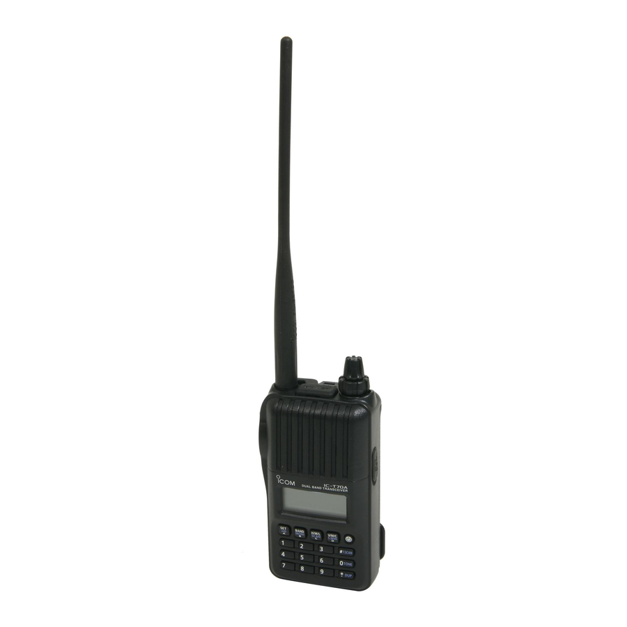
ACCESSORY ATTACHMENT ■ Battery pack ■ Antenna To attach the battery pack: Insert the antenna connector into the antenna base and q Fit the battery pack tighten the antenna screw. Battery pack/Battery case in the direction of the Jack cover arrow (q), then close. -
Page 10: Panel Description
PANEL DESCRIPTION ■ Front, top and side panels q ANTENNA CONNECTOR (p. 2) ANTENNA Connects to the supplied antenna. CONNECTOR • An optional AD-92SMA adapter (p. 79) is available for connect- EXTERNAL SPEAKER/ ing an antenna with a BNC connector. MICROPHONE JACKS w EXTERNAL SPEAKER/MICROPHONE JACKS [SP/MIC] CONTROL DIAL... - Page 11 ■ ■ SI ■ ES ■ ■ ■ ■ ■ ■ ■ ■ ■ ■ ■ ■ ■ ■ A-6808H-1EX-t Printed in Japan 2009–2016 Icom Inc. © 1-1-32 Kamiminami, Hirano-ku, Osaka 547-0003, Japan Printed on recycled paper with soy ink.
Need help?
Do you have a question about the IC-T70A and is the answer not in the manual?
Questions and answers