Table of Contents
Advertisement
Advertisement
Table of Contents

Related Manuals for JBL LSR


Summary of Contents for JBL LSR
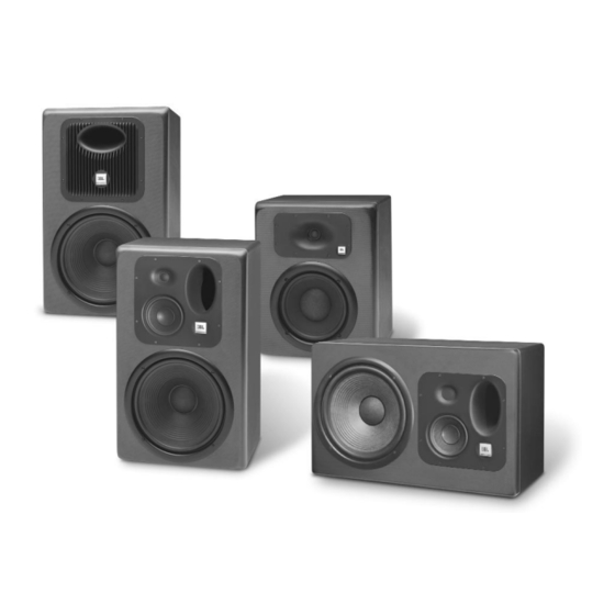
- Page 1 LSR Linear Spatial Reference Studio Monitor System Owner’s Manual...
-
Page 2: Important Safety Instructions
The IEC fuse symbol pictured at the left represents an approved, user replaceable fuse. When replacing a fuse, make sure to replace with only the correct type and fuse rating. 1. Read Instructions – Before operating your new JBL LSR product, please read all safety and operating instructions. - Page 3 More Safety Instructions 8. Grounding and Power Cords – The power cord supplied with your powered LSR product has a 3-pin type plug. Do not cut off or damage the grounding pin and once again, don’t use in a shower. If the provided plug does not fit into your outlet, consult an electrician for replacement of the obsolete outlet.
-
Page 4: Table Of Contents
Table of Contents 1.0 Introduction ........................Page 2 2.0 Getting Started ........................Page 3 2.1 Unpacking............................Page 3 2.2 Placement............................Page 3 2.3 Audio Connections .......................... Page 4 2.4 AC Power Connections ........................Page 5 2.5 Making Sound Happen ........................Page 5 3.0 LSR32 3-Way Monitor ...................... -
Page 5: Introduction
Beginning with a blank CAD screen, today’s equivalent to a clean sheet of paper, the LSR products have been based on fundamental research into all aspects of monitor design. JBL designed the entire system starting with the materials and topologies of the individual transducers, through to the final assembly of the diecast parts. -
Page 6: Getting Started
2.2 Placement: The design of the LSR systems lend themselves to a wide variety of placement options. Covered here is a typical stereo setup for near to mid field monitoring. A deeper discussion of multi-channel sound setup is available from JBL in Tech Note Volume 3, Number 3. -
Page 7: Audio Connections
Angling towards the listening position: LSR monitors should be angled to directly face the listener. The center of the high frequency transducer should be on-axis with the ear level of the listener. -
Page 8: Ac Power Connections
IEC plug is required by wiring codes and regulations. It must always be connected to the electrical installation safety ground. The LSR units have carefully designed internal grounding and bal- anced inputs and outputs to reduce the possibility of ground loops (hum). If hum occurs, see Appendix A for suggested audio signal wiring and system grounding. -
Page 9: Lsr32 3-Way Monitor
Section 3. - LSR32 GENERAL OPERATION 3.0 Basic Introduction The LSR32 Linear Spatial Reference Studio Monitor combines JBL’s latest in transducer and system technology with recent breakthroughs in psychoacoustic research to provide a more accurate studio reference. The neodymium 12" woofer is based on JBL’s patented Differential Drive ®... -
Page 10: High Frequency Adjustment
Use only two conductor insulated and stranded speaker wire, preferably no smaller than 14 AWG. Cable runs exceeding 10 meters (30 feet) should be made with heavier wire, 12 or 10 AWG. 3.2 High Frequency Adjustment: The LSR32 High Frequency level can be adjusted to compensate for placement or “bright” rooms. The unit is shipped in the “flat”... -
Page 11: Lsr28P 2-Way Bi-Amplified Monitor
Using a combination of advanced transducer engineering and powerful drive electronics, the LSR28P will stand up to the most demanding sessions. The 8” woofer is based on JBL’s patented Differential Drive ® technology. With dual 1.5” drive coils, power compression is kept to a minimum to reduce spectral shift as power levels increase. -
Page 12: Audio Level Adjustment
The ground terminal of the IEC plug is required by wiring codes and regulations. It must always be connected to the electrical installation safety ground. The LSR units have carefully designed internal ground- ing and balanced inputs and outputs to reduce the event of ground loops (hum). If hum occurs, see Appendix A for suggested correct audio signal wiring and system grounding. -
Page 13: Low Frequency Adjustments
4.4 Low Frequency Adjustments: The low frequency response of the LSR28P can • be adjusted to increase or reduce the output level. This is typically done when the system is located near a wall +2 dB/36 dB Octave • or other boundary surface. With all bass adjustment •... -
Page 14: Lsr12P Active Subwoofer
Section 5. - LSR12P ACTIVE SUBWOOFER The LSR12P Active Subwoofer consists of a high powered Differential Drive ® 12” neodymium woofer integrated with a powerful 250 watt continuous power output amplifier. The active drive circuitry has been developed to maximize the acoustic output power while maintaining overall low distortion and high transient performance. -
Page 15: Ac Power Connections
The ground terminal of the IEC plug is required by wiring codes and regulations. It must always be connect- ed to the electrical installation safety ground. The LSR units have carefully designed internal grounding and balanced inputs and outputs to reduce the event of ground loops (hum). If hum occurs, see Appendix A for suggested correct audio signal wiring and system grounding. -
Page 16: Low Frequency Characteristics
5.4 Changing Low Frequency Characteristics: Switch 4 reverses the polarity of the LSR12P. At the crossover point between the subwoofer and satel- lite speakers, it is important that all systems are in the correct polarity. If the subwoofer and the satellite woofers are in the same vertical plane, the polarity should be set to normal. -
Page 17: Led Indication
5.6 LED Indication: A multicolor LED indicator is located on the front of the LSR12P. In normal operation, this LED will be GREEN. When the LSR12P is in bypass mode, the LED will turn AMBER. This indicates that the high pass filters on the three outputs are bypassed and the subwoofer feed is from the discrete input. -
Page 18: Specifications
For this reason, any current Dimensions (WxHxD): 63.5 x 39.4 x 29.2 cm (25.0 x 15.5 x 11.5 in.) JBL product may differ in some respect from its published description, but will always equal or exceed the original design specifications unless otherwise stated. - Page 19 Acoustic Contribution Impulse Response Power Compression System Impedance 1 – 10 WATTS 2 – 30 WATTS 3 – 100 WATTS LSR32 Response Curves 1. On-Axis Response 2. Spatially Averaged Response over a range of +/- 30° Horizontal & +/- 15° Vertical 3.
-
Page 20: Lsr28P
Baffle Construction: Carbon Fiber Composite products without notice as a routine expression of that philosophy. For this rea- son, any current JBL product may differ in some respect from its published Cabinet Construction: 19mm (3/4” M.D.F.) description, but will always equal or exceed the original design specifications Net Weight: 22.7 kg (50 lbs) - Page 21 Impulse Response Acoustic Contribution LSR28P Response Curves 1. On-Axis Response 2. Spatially Averaged Response over a range of +/- 30° Horizontal & +/- 15° Vertical 3. First Reflection Sound Power 4. Total Radiated Sound Power 5. DI of On-Axis Response 6.
-
Page 22: Lsr12P
For this rea- son, any current JBL product may differ in some respect from its published Dimensions (WxHxD): 63.5 x 39.4 x 29.2 cm (25.0 x 15.5 x 11.5 in.) description, but will always equal or exceed the original design specifications unless otherwise stated. -
Page 23: Appendix A
Appendix A: Wiring Recommendations By now, you have probably plugged the LSR monitors in and are making great music. However, for optimum performance, some attention to wiring details now can reduce system degradation later. These cabling recommendations follow standard wiring practice for differential inputs. - Page 24 LSR monitor using twisted pair cable. Note that the shield is connected to the GROUND/SHIELD connec- tor at the LSR input, but not at the source. This reduces the likelihood of introducing a ground loop into the system.
- Page 25 Figure E details the connections using unbalanced cable and Tip/Sleeve connections to the 1/4” input. In this mode, the Ring and Sleeve of the LSR input are shorted by the plug automatically. Unbalanced Source LSR T/R/S Input Ring Sleeve Sleeve...
- Page 27 JBL Professional 8500 Balboa Boulevard, P.O. Box 2200 Northridge, California 91329 U.S.A. LSR MANUAL CRP 1M A Harman International Company 8/98...
Need help?
Do you have a question about the LSR and is the answer not in the manual?
Questions and answers