
Related Manuals for Clarke WOODWORKER CTS800B


Summary of Contents for Clarke WOODWORKER CTS800B
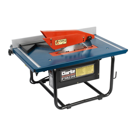
- Page 1 8” (200mm) TABLE SAW 8” (200mm) TABLE SAW Model: CTS800B OPERATING & MAINTENANCE INSTRUCTIONS © 0606...
-
Page 2: Before Use
PLEASE READ THIS MANUAL THOROUGHLY BEFORE USE. f you have any problems using, or setting up this machine, please ring the CLARKE helpline... 020 8988 7400 020 8988 7400 • Press 1 for Parts • Press 2 for Technical Assistance... -
Page 3: Table Of Contents
Thank you for purchasing this CLARKE 8” (200mm) Table Saw, which is designed for DIY and hobby use, to rip and cross cut wood exclusively, up to maximum thickness of 40mm. Please read ‘Restrictions Of Use’ below. Before attempting to operate this machine, please read this instruction manual thoroughly and follow all directions carefully. -
Page 4: Safety Precautions
SAFETY PRECAUTIONS As with all machinery, there are certain hazards involved with their operation and use. Exercising respect and caution will considerably lessen the risk of personal injury. However, if normal safety precautions are overlooked or ignored, personal injury to the operator or damage to property may result. - Page 5 18. BEFORE USING THE MACHINE, check for damage. If a guard, or other part is found to be damaged, it should be carefully checked to ensure that it will operate properly and perform its intended function. Check for alignment, binding, or breakage of parts, mountings, and any other conditions that may affect its operation.
-
Page 6: Electrical Connections
ELECTRICAL CONNECTIONS Connect the mains lead to a standard 230 volt (50Hz) electrical supply via a 13 amp BS1363 plug fitted with a 5 amp fuse. WARNING: THIS APPLIANCE MUST BE EARTHED. IMPORTANT: The wires in the mains lead are coloured in accordance with the following code: Green &... -
Page 7: Pre-Assembly Check
PRE-ASSEMBLY CHECK Unpack your Table Saw and lay out the various components, checking to ensure that all parts detailed below have been supplied. Should any of the components be missing or damaged then please contact your dealer immediately. Table Saw with fitted plug Rip Fence assembly Push Stick Cross Cut Guide... -
Page 8: Mounting Your Table Saw
MOUNTING THE SAW If the Saw is to be bolted to a workbench, you should ensure that it is positioned in the most convenient location. Ensure adequate lighting is available and the electrical supply is close at hand. A mounting board should be used if a permanent mounting is unavailable or not desired. -
Page 9: Dust Extraction
DUST EXTRACTION This table saw is equipped with a dust extraction port at the rear of the machine. For safe operation, we recommend that a suitable dust extraction device or vacuum cleaner is connected during operation. WARNING: Excessive sawdust build up around the motor could possibly ignite and cause damage to either the motor, table saw or your workshop. -
Page 10: Cross Cutting
NOTE: The Rip fence can be mounted left or right hand side of blade. Hold workpiece against the Rip Fence and feed through blade. Do not force it. If the motor slows, feed more slowly. NEVER hold on to offcut of the wood. If sawing long lengths of material, arrange a support at the rear of the machine, or use an assistant to support the material as it runs off. -
Page 11: Bevel Cutting
BEVEL CUTTING Rip and cross cuts can be made at Fig.7 angles between 0 - 45 Slacken the Blade securing knobs, front and rear (Front knob is arrowed in Fig.7). Turn the Adjuster handle as required to the desired angle as indicated on the scale. -
Page 12: Replacing The Saw Blade
REPLACING THE SAW BLADE Fig.8 Remove the side cover by unscrewing the five securing screws. Place a steel bar or screwdriver blade between the table top and one of the saw blade teeth, (at the point arrowed in Fig.8), then undo the saw blade securing nut - normal right hand thread. -
Page 13: Specifications
** This denotes that this machine may be used for 3 minutes only, in any 10 minute period. Please note that CLARKE International reserves the right to modify design at any time without prior notice. Any significant change will be reflected in this manual. -
Page 14: Parts List & Diagrams
PARTS LIST No. Description Part No. No. Description Part No. 31 Handle GRCTS800B31 Foot Support GRCTS800B01 32 Screw GRCTS800B32 Frame GRCTS800B02 33 Sleeve GRCTS800B33 Screw GRCTS800B03 34 Shaft GRCTS800B34 Spring Washer GRCTS800B04 35 Box GRCTS800B35 Washer GRCTS800B05 36 Screw GRCTS800B36 Motor Support GRCTS800B06 37 Nut... - Page 15 PARTS DIAGRAM...
Need help?
Do you have a question about the WOODWORKER CTS800B and is the answer not in the manual?
Questions and answers