
Subscribe to Our Youtube Channel
Related Manuals for Clarke Contractor CTS12


Summary of Contents for Clarke Contractor CTS12
- Page 1 © 0207 10” TABLE SAW 10” TABLE SAW Model CTS12 Model CTS12 Part Number 6500750 Operating & Maintenance Instructions...
-
Page 2: Specifications
SPECIFICATIONS Model No ..........CTS12 Part No........... 6500754 Motor ............. 230V~ 50Hz 1ph Power rating ......1.5Kw Speed ........6270 rpm Fuse rating ......... 13Amps Saw Blade ..........10” dia. (254x30mm) TCT Maximum depth of cut at 0 ....75 mm Maximum depth of cut at 45 .... -
Page 3: Table Of Contents
Thank you for purchasing your new CLARKE 10” TABLE SAW. Before attempting to operate this machine, please read this instruction manual thoroughly and follow all directions carefully. In doing so you will ensure the safety of both yourself and others around you, and, at the same time, you should look forward to it providing long and trouble free service. -
Page 4: Safety Instructions
SAFETY INSTRUCTIONS KEEP WORK AREA CLEAN : Cluttered areas and benches invite injuries. CONSIDER WORK AREA ENVIRONMENT: Do not expose power tools to rain. Do not use power tools in damp, or wet locations. Keep the work area well lit. Do not use this saw in the presence of flammable liquids or gases. - Page 5 SAFETY INSTRUCTIONS USE OUTDOOR EXTENSION LEADS: When the tool is used outdoors, use only extension leads intended for outdoor use and so marked. Always make sure that the extension lead is suitably rated for the tool. Position the extension lead so that it does not create a hazard. STAY ALERT: Watch what you are doing.
- Page 6 SAFETY INSTRUCTIONS USE THE MITRE GAUGE: Always hold the work firmly against the mitre gauge fence when cross cutting. LOCK THE GUIDES: Always ensure the rip fence is securely fastened when in use. USE A PUSH STICK: Use a pushstick to feed the workpiece past the saw blade. The push stick should always be stored with the machine when not in use.
-
Page 7: Additional Safety Rules For Table Saws
ADDITIONAL SAFETY RULES FOR TABLE SAWS ✔ ALWAYS use saw Blade Guard and Riving Knife for every operation. ✔ ALWAYS hold the work firmly against the mitre gauge or fence. ✔ ALWAYS use a push-stick when required. Always use a push-stick for ripping narrow stock. Refer to ripping applications in instruction manual where push-stick is covered in detail. -
Page 8: Electrical Connections
ELECTRICAL CONNECTIONS WARNING! THIS APPLIANCE MUST BE EARTHED. Connect the mains lead to a 230 volt (50Hz) domestic electrical supply via a standard 13 amp BS 1363 plug fitted with a 13 amp fuse, or a suitably fused isolator switch. IMPORTANT: The wires in the mains lead are coloured in accordance with the following code: Green &... -
Page 9: Features
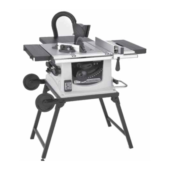
FEATURES Fig.1 To transport the the machine, turn the assembly on its side, resting on the table wheels, then collapse the legs. The Handle may now be used to move the table saw as required. -
Page 10: Glossary Of Terms
FEATURES 1. The switch panel incorporates the ON and OFF switches. Your saw also features an Overload Protection device, so that if the motor overheats (due to feed pressure being too great, dull blade or low voltage), the Overload Relay will intervene, and the motor will automatically cut out. -
Page 11: Unpacking And Checking Contents
13. Riving knife (with laser cutting guide attached) x 1 14. Fixings pack (nuts & bolts etc) x 1 Should any component be missing or damaged in transit, please contact your CLARKE dealer immediately, or CLARKE Customer Service Department on 020 8558 7400... -
Page 12: Assembly
ASSEMBLY A. TABLE EXTENSION Loosen the extension table clamps. Fig.2 Slide the extension table into the two holes on the side of the table saw. Secure each extension table by tightening up the extension table clamps. Fig. 3 B. PUSH STICK STORAGE Store the Push Stick in the holder provided. - Page 13 Slide the Riving Knife into position, and adjust the Riving knife so that a clearance of no more than 5mm exists between blade and knife, and along the full length of the riving knife, as illustrated in Fig. 5 Fig.5 ✔...
- Page 14 E. RIP FENCE Fig.8 The rip fence has the following parts: 1. The handle assembly ‘A’ 2. The fence ‘B’ 3. Two fixings, each comprising a coach bolt and securing knobs ‘C’. Slide the handle assembly (A) into the slot in the front rail, and push the handle down to lock the rip fence to the table.
-
Page 15: Mounting The Saw On To The Stand
MOUNTING THE SAW ON TO THE STAND STAND SETUP Fig.10 The Stand is supplied flat. Stand the assembly on its two wheels. Pull the front pair of legs down and out as shown until they click into place. Repeat the process with the second pair of legs. Fig.11 Fig.12 The stand should appear as shown in Fig.12. -
Page 16: Important Checks Before Starting
IMPORTANT CHECKS - BEFORE STARTING IMPORTANT: Before attempting to use the machine, it is necessary to ensure the various components are correctly adjusted, and securely fitted. • Make sure that the blade is securely fitted. • Ensure the Blade Guard is fitted securely and capable of dropping under its own weight. •... -
Page 17: Adjustment
OVERLOAD CUT-OUT Your table saw features an OVERLOAD CUTOUT device, so that if the motor overheats (due to feed pressure being too great, a dull blade or low voltage etc.), the motor will automatically cut out. In this event, Switch the machine OFF by pressing the red button ‘O’, Unplug the machine from the mains supply and allow the machine to cool for three to five minutes before plugging in and attempting to restart. -
Page 18: Using The Mitre Gauge
USING THE MITRE GAUGE Fig.16 Screw the mitre gauge fence to the quadrant, using the two securing wheels. As shown. Slide the mitre gauge into one of the slots on the top of the table. Loosen the lock knob and set the mitre gauge to the required angle. - Page 19 ADJUSTING THE RIP FENCE Fig.19 Lift the fence handle up. Slide the rip fence to the position you require. Push the fence handle down to lock the Rip Fence into place. ADJUSTING THE LASER GUIDE Fig.20 To align the laser guide proceed as follows. Set the blade angle to 0 Remove the blade guard.
-
Page 20: Cutting Practices
CUTTING PRACTICES RIPPING OR RIP CUTTING Fig.22 Ripping means to cut a piece of timber in the same direction as the grain, i.e usually lengthwise. • The rip fence can be positioned to the right or left of the saw blade, and can be adjusted to suit the width of cut required, Lock the rip fence into position. -
Page 21: Auxiliary Fence
PUSH STICK AND PUSH BLOCK Fig.26 Make the Push Block using pieces of 10mm plywood 304mm and 19mm hardwood as shown in Fig.26. • The small piece of wood 10x10x64mm should be GLUED to the plywood. DO NOT USE NAILS or SCREWS. - Page 22 WHEN CROSSCUTTING: Do not make cuts freehand (without using the mitre gauge or other auxiliary device) the blade may bind in the cut and cause kickback or cause your fingers or hand to slip into the blade. Always lock the mitre gauge when in use. Remove rip fence from table when not in use.
-
Page 23: Mitre Cutting
MITRE CUTTING Fig.31 Mitre cutting is the term used for cutting at an angle other than 90 to the edge of the wood. Adjust the mitre gauge to the desired angle, and lock • The mitre gauge may be used in either of the grooves in the table. -
Page 24: Maintenance
A coat of wax applied to the table will help to keep the surface clean and allow wood being cut to slide more freely. CHANGING THE BLADE • Use only Clarke Blades, (see parts list for part numbers). • Replace the blade when teeth become damaged or dull. WARNING! TO PREVENT PERSONAL INJURY, ALWAYS DISCONNECT PLUG FROM POWER SOURCE BEFORE CHANGING BLADES. -
Page 25: Adjusting The Positive Stops
ADJUSTING 90 AND 45 DEGREE POSITIVE STOPS WARNING! ENSURE THE PLUG IS DISCONNECTED FROM THE POWER SUPPLY BEFORE PROCEEDING Fig.34 ADJUSTING THE POSITIVE STOPS Raise the blade to maximum height. Turn machine so that it rests on the table top’s side edge and is supported in some way, ensuring it is stable. -
Page 26: Trouble Shooting
TROUBLE SHOOTING TROUBLE PROBABLE CAUSE REMEDY Saw will not start 1. Saw not plugged in 1. Plug in the machine 2. Fuse blown or circuit breaker 2. Replace fuse or reset circuit tripped breaker 3. Power cable damaged 3. Have cable replaced by authorised service centre Does not make 1. -
Page 27: Parts Lists And Diagrams
PARTS LISTS No. Description Part No No. Description Part No Hex bolt DDCTS12041 Side extension table DDCTS12001 Hex bolt DDCTS12042 Rubber foot DDCTS12002 Left stand assy. DDCTS12043 Flat washer DDCTS12003 Foot block DDCTS12044 Cross tapping screw DDCTS12004 Cross tapping screw DDCTS12005 Adjustable foot DDCTS12045... - Page 28 No. Description Part No No. Description Part No Screw DDCTS12120 Slide bar clamp DDCTS12081 Threaded spindle DDCTS12121 Left guard DDCTS12082 Bolt DDCTS12122 Screw DDCTS12083 Spring DDCTS12123 Handle 2 DDCTS12084 Gear DDCTS12124 Handle 1 DDCTS12085 Belt DDCTS12125 Handle cover DDCTS12086 Drive wheel DDCTS12126 Hand wheel B DDCTS12087...
- Page 29 PARTS DIAGRAM Fig.37...
-
Page 30: Parts Diagram
Fig.38 PARTS AND SERVICE CONTACTS For Spare Parts and Service, please contact your nearest dealer, or CLARKE International, on one of the following numbers. PARTS & SERVICE TEL: 020 8988 7400 PARTS & SERVICE FAX: 020 8558 3622 or e-mail as follows: PARTS: Parts@clarkeinternational.com...
Need help?
Do you have a question about the Contractor CTS12 and is the answer not in the manual?
Questions and answers