User Manuals: Magnum Energy MS Series Inverter Charger
Manuals and User Guides for Magnum Energy MS Series Inverter Charger. We have 3 Magnum Energy MS Series Inverter Charger manuals available for free PDF download: Owner's Manual, Removal And Replacement
Magnum MS Series Owner's Manual (82 pages)
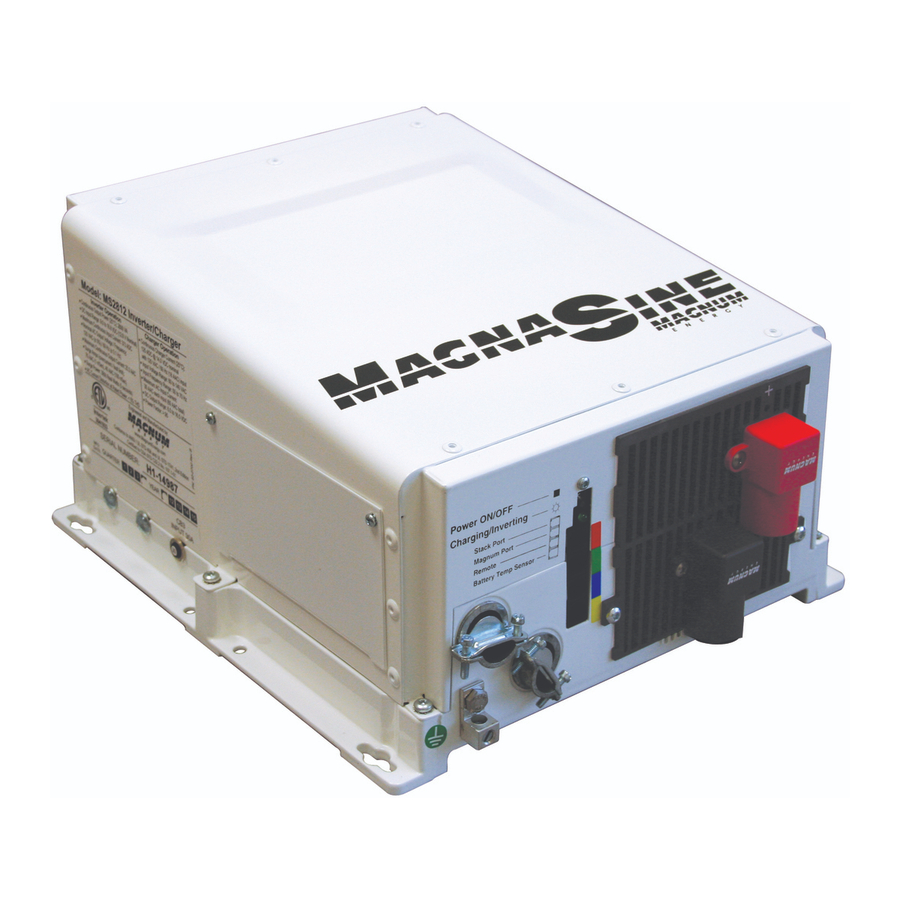
MS Series Pure Sine Wave Inverter/Charger
Table of Contents
Advertisement

Magnum Energy MS Series Owner's Manual (64 pages)
MS Series Pure Sine Wave Inverter/Charger
Brand: Magnum Energy
|
Category: Inverter
|
Size: 2 MB
Table of Contents
Magnum Energy MS Series Removal And Replacement (2 pages)
Inverter/Charger DC Terminal Plate
Brand: Magnum Energy
|
Category: Inverter
|
Size: 0 MB
Advertisement