Table of Contents
Advertisement
Advertisement
Table of Contents

Related Manuals for Honeywell Horizon 7600


Summary of Contents for Honeywell Horizon 7600
- Page 1 Horizon™ 7600 Presentation Laser Imager Installation and User’s Guide...
- Page 2 Disclaimer Honeywell International Inc. (“HII”) reserves the right to make changes in specifications and other information contained in this document without prior notice, and the reader should in all cases consult HII to determine whether any such changes have been made. The information in this publication does not represent a commitment on the part of HII.
-
Page 3: Table Of Contents
Table of Contents Introduction ......................1 Base Kit Components ..................2 Optional Accessories ..................2 Replacement Parts ................... 3 Scanner Parts ....................4 Maintenance ..................... 5 Scanner Labels ....................6 Mounting ......................8 Before Installing Your 7600 ................8 Mounting the 7600 Series ................. 9 Option A: Shelf Support ................. - Page 4 Limited Warranty ....................50 Regulatory Compliance ................... 52 Index ........................54 Customer Support .................... 55 Technical Assistance ..................55 Product Service and Repair ................56...
-
Page 5: Introduction
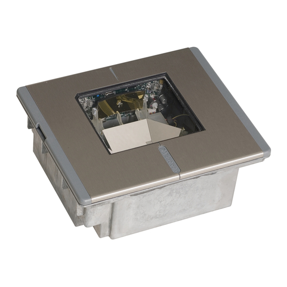
Introduction The Horizon™ 7600 series is Honeywell’s next generation in-counter laser bar code scanner. This compact, hands-free scanner is designed with a dense 20-line omnidirectional scan pattern that helps provide fast, efficient throughput with a high first pass read rate. -
Page 6: Base Kit Components
Description MS7600 Horizon Series Scanner ® 00-02407 MetroSelect Programming Guide 00-02870 Horizon 7600 Installation and User’s Guide 52-52511A 24" EAS cable Guides also available for download at www.honeywellaidc.com. Optional Accessories Part # Description 46-46640 Point of Sale (POS) USB Plug Straight PowerLink Cable with built in power jack. -
Page 7: Replacement Parts
Part # Description AC to DC Power Transformer - Regulated 5.2V@ 1A output 46-46759 120V United States 46-46616 220V – 240V Continental European 46-46615 220V – 240V United Kingdom 46-46984 220V – 240V China 46-46985 220V – 240V Australia 46-46641 Stainless Steel Trim Ring Replacement Parts Part #... -
Page 8: Scanner Parts
Scanner Parts Figure 1: Scanner Parts Output Window (Laser Aperture) Amber LED (Located Under Window) Red LED (Located Under Window) Speaker Cable Connection Area ... -
Page 9: Maintenance
Maintenance Smudges and dirt can interfere with the proper scanning of a bar code. Therefore, the output window will need occasional cleaning. For the 7600 glass window: Spray glass cleaner onto lint free, non-abrasive cleaning cloth. Gently wipe the scanner window. For the 7600 red window: Use mild soap and water with lint free, non-abrasive cleaning cloth. -
Page 10: Scanner Labels
Scanner Labels Each scanner has a label on the bottom of the unit. The label contains information such as the model number, date of manufacture, serial number, and caution information. An additional caution label is located under the top plate. The following are examples of these labels. - Page 11 MS7625 Series Only (except RS485 Interface) If the following label is attached to your product, the product meets Korean agency approval for Class A equipment. 이 기기는 업무용(A급) 전자파적합기기로서 판매자 또는 사용자는 이 점을 주의하시기 바라며,가정외의 지역에서 사용하는 것을 목적으로 합니다.
-
Page 12: Mounting
Mounting Before Installing Your 7600 When mounting the 7600 or replacing the Top Plate: Turn Figure 3 the unit upside down. Press Figure 4 on the window. Lift the Top plate straight up to remove. There is no hardware required to remove or replace the top cover. -
Page 13: Mounting The 7600 Series
Mounting the 7600 Series There are three options for mounting your 7600. Option A uses a shelf to support the unit. Option B lets the unit hang free in the counter top. Option C lets the unit hang free in the counter top with the use of a stainless steel trim ring for support. -
Page 14: Option B: Free Hanging Support
Option B: Free Hanging Support Figure 10: Package Flow (right) Figure 11: Specifications for Free Hanging Support Figure 12: Installation Tabs... -
Page 15: Option C: Trim Ring
Option C: Trim Ring Figure 13: Counter Top Opening for Trim Ring (PN 46-46641) Figure 14: Trim Ring (PN 46-46641) Installation... -
Page 16: Installation
Installation Keyboard Wedge Turn off the host system. Disconnect the keyboard from the host. Connect the PowerLink cable to the jack from the top of the 7600. Connect the “Y” end of the PowerLink cable to the keyboard and the keyboard port on the host. If necessary use the male/female adapter cable supplied with the scanner for proper connections. -
Page 17: Stand-Alone Keyboard
Stand-Alone Keyboard Turn off the host system. Disconnect the keyboard from the host. Connect the PowerLink cable to the 2 jack from the top of the 7600. Connect the other end of the PowerLink cable to the keyboard port on the host. Before continuing verify that the PowerLink cable is connected to the appropriate interface jack on the... -
Page 18: Usb
Turn off the host system. Determine if your application requires USB Keyboard communication protocols or USB Point of Sale communication protocols. If you require USB Keyboard communication protocols, skip to step 4. Figure 17: POS Plug Installation If you require USB Point of Sale communication protocols: •... - Page 19 Manufacturers Note: Plugging the scanner into the USB port of the PC does not guarantee that scanned information will appear at the PC. A software driver and correct configuration setting may also be required for proper communication to occur. Scan the Enable USB Defaults bar code to configure the 7600 for USB communication.
-
Page 20: Rs232 Or Light Pen
RS232 or Light Pen Turn off the host system. Connect the PowerLink cable into the 1 jack down from the top of the 7600. Connect the other end of the PowerLink cable to the host. Before continuing verify that the PowerLink cable is connected to the appropriate interface jack on the scanner. - Page 21 For RS232 Communication: Recall Defaults ³ Scan 1 Enable RS-232 ³ Scan 2 For Light Pen Communication: Recall Defaults ³ Scan 1 Enable Light Pen/Wand ³ Scan 2...
-
Page 22: Rs485
RS485 Turn off the host system. Connect the MVC cable to the jack down from the top of the 7600. Connect the other end of the MVC cable to the host. Before continuing verify that the MVC cable is connected to the appropriate interface jack on the scanner. -
Page 23: Ocia
OCIA Turn off the host system. Connect the MVC cable to the jack down from the top of the 7600. Connect the other end of the MVC cable to the host. Before continuing verify that the MVC cable is connected to the appropriate interface jack on the scanner. -
Page 24: Secondary Scanner
Connect the other end of the PowerLink RS232 AUX cable into the 3 jack down from the top of the 7600. The following Honeywell scanners can be used in the “Aux” input of the MS7600: the MS9520, MS9540, MS7220, MS7120, MS6720, MS6220, MS6520, MS5145 or another 7600. - Page 25 The following bar codes do not apply when using an MS6720 as a secondary scanner. Contact a customer service representative for additional information on the MS6720. If the secondary scanner is not a Honeywell scanner refer to Section O of the MetroSelect Configuration Guide. Enable Aux Port ³...
-
Page 26: Connector Orientation
Figure 22: Connector Orientation Figure 23: Secondary Scanner Setup... -
Page 27: Eas
SW1 and SW2 are the switch banks inside the Checkpoint Device that set the deactivation range. Honeywell recommends end users program the 7600 to the Fixed Low-Density depth of field, so that the unit does not scan out beyond the deactivation range. -
Page 28: Operation
Operation Audible Indicators When the 7600 scanner is in operation, it provides audible feedback. These sounds indicate the status of the scanner. Eight settings are available for the tone of the beep (normal, 6 alternate tones and no tone) plus three volume settings. -
Page 29: Visual Indicators
Visual Indicators There is a red LED and amber LED on the front of the 7600. When the scanner is on, the flashing or constant illumination of the LEDs indicates the status of the current scan and the scanner. Figure 25: LEDs No Red or Amber LED The LEDs will not be illuminated if the scanner is not receiving power from the host or transformer. -
Page 30: Failure Modes
Failure Modes Figure 26: LEDs Flashing Amber and One Razzberry Tone This indicates the scanner has experienced a laser subsystem failure. Return the unit for repair at an authorized service center. Flashing Red and Amber and Two Razzberry Tones This indicates the scanner has experienced a motor failure. -
Page 31: Changing The Beeper Tone & Volume
Changing the Beeper Tone & Volume Changing the Beeper Tone Beeper tones may be programmed directly or incrementally using the following bar code. The new tone will be heard followed by a short pause. Two more new tones will be heard signifying the new setting has been stored in memory. The silent (no beep) tone is also selectable. -
Page 32: Power Save Modes And Ir Detection
Power Save Modes and IR Detection The 7600 has five programmable power save modes. Refer to the MetroSelect Programming Guide for additional information on Power Save Modes. Blink Power Save Mode: Blinks the laser OFF & ON after a programmed period of non-use. When the scanner recognizes a bar code it will exit the Blink mode. - Page 33 Figure 28: IR Activation Area Parallel to Package Flow Specifications are subject to change without notice.
-
Page 34: Scan Volume Specifications
Scan Volume Specifications 100% UPC B ASED ON ODES Figure 29: Scan Volume in Plane Perpendicular to Flow Figure 30: Scan Volume in Plane Parallel to Flow Specifications subject to change without notice. -
Page 35: Depth Of Field By Minimum Bar Code Element Width
Depth of Field by Minimum Bar Code Element Width 100% UPC B ASED ON ODES Figure 31: Depth of Field Perpendicular to Flow Minimum Bar Code Element Width mils 10.4 Specifications subject to change without notice. -
Page 36: Troubleshooting
Troubleshooting The following guide is for reference purposes only. Contact a customer service representative to preserve the limited warranty terms. SYMPTOMS POSSIBLE CAUSE(S) SOLUTION All Interfaces Check transformer, outlet and No power is being No LEDs, beep power strip. Make sure the supplied to the or motor spin. - Page 37 SYMPTOMS POSSIBLE CAUSE(S) SOLUTION UPC/EAN, Code 39, interleaved Scanning a particular 2 of 5, Code 93, Code 128 and symbology that is not Codabar are enabled by default. enabled. Verify that the type of bar code being read has been selected. The unit powers up, but does The scanner has been...
- Page 38 SYMPTOMS POSSIBLE CAUSE(S) SOLUTION The bar code may Check if it is a check have been printed digit/character/or border incorrectly. problem. Scanner beeps The scanner is not at some bar configured correctly Check if check digits are set codes and NOT for this type of bar properly.
- Page 39 SYMPTOMS POSSIBLE CAUSE(S) SOLUTION Everything These characters may works except not be supported by Try operating the scanner in Alt for a couple of that country’s key look mode. characters. up table. RS-232 Only Increase the interscan code The unit is delay setting.
- Page 40 SYMPTOMS POSSIBLE CAUSE(S) SOLUTION Add some intercharacter delay Intercharacter delay to the transmitted output by Characters are needs to be added to using the MetroSelect being dropped. the transmitted output. Programming Guide 00-02407). Aux port operation with any interface Trouble with the Refer to the user guide provided Secondary with the secondary scanner.
-
Page 41: Design Specifications
Scan Lines: Min Bar Width: 0.127 mm (5.0 mil) Autodiscriminates all standard bar codes; for other Decode Capability: symbologies call Honeywell PC Keyboard Wedge, RS-232, OCIA, Light Pen, System Interfaces: Stand Alone PC Keyboard, USB, RS485 Print Contrast: 35% minimum reflectance difference up to 80 data characters(Maximum number will vary No. - Page 42 Electrical Input Voltage: 5.2VDC ± 0.25V Power: 2.6 W Operating Current: 500 mA Laser Off Power Save Mode = < 350 mA Standby Current: Laser/Motor Off Power Save Mode = <165 mA DC Transformers: Class II; 5.2 V @ 1A Laser Class: IEC 60825-1:2007 Class 1 EMC:...
-
Page 43: Applications And Protocols
The 7600 with Built-in PC Keyboard Wedge Interface is designed to be used for keyboard emulation only. Many RS-232 programmable functions available in other Honeywell scanners are also available as keyboard wedge functions. The following are the most important selectable options specific to the keyboard wedge. -
Page 44: Default Settings
Default Settings Many functions of the scanner can be "programmed" - that is, enabled or disabled. The scanner is shipped from the factory programmed to a set of default conditions. The default parameter of the scanner has an asterisk ( * ) in the charts on the following pages. If an asterisk is not in the default column then the default setting is Off or Disabled. - Page 45 IGHT OCIA RS-232 RS485 ARAMETER EFAULT Bars High as Scanned Spaces High as Scanned DTS/SIEMENS DTS/NIXDORF NCR F NCR S Poll Light Pen Source Beeper Tone Normal Before ...
- Page 46 IGHT OCIA RS-232 RS485 ARAMETER EFAULT Number of Scan Buffers Transmit EAN-8 Check Digit Transmit EAN-13 Check Digit Transmit UPC-A Check Digit ...
- Page 47 IGHT OCIA RS-232 RS485 ARAMETER EFAULT UPC Suffix Transmit AIM ID Characters STX Prefix ETX Suffix Carriage Return Line Feed - disabled by ...
- Page 48 IGHT OCIA RS-232 RS485 ARAMETER EFAULT as code Coupon Code 128 Programmable Code Lengths 7 avail. Programmable Prefix 10 avail. Characters Suffix Characters Prefixes for individual Code ...
- Page 49 Default settings for “Aux” interface The secondary scanner and the 7600 always communicate via RS232. Data is relayed to the host via various primary interfaces. IGHT OCIA RS-232 RS485 ARAMETER EFAULT Aux Baud Rate 38400 ...
-
Page 50: Scanner And Cable Terminations
Scanner and Cable Terminations Scanner Pinout Connections The 7600 scanner interfaces terminate to 10-pin modular jacks located on the back of the unit. The serial # label indicates the model number of the scanner. Figure 32: Scanner Interface Ports MS762x-13 OCIA MS762x-13 RS485 Function Function... - Page 51 Figure 33: Scanner Interface Ports MS762x-37 MS762x-37 Keyboard Wedge, RS-232 or Light Pen Stand-Keyboard or USB Function Function Ground Ground USB D- RS-232 Transmit Output USB D+ RS-232 Receive Input PC Data RTS Output PC Clock CTS Input KB Clock DTR Input/LTPN Source PC +5V, V-USB KB Data...
- Page 52 Cable Connector Configurations (Host End) PowerLink Cable 54-54xxx* Function Shield Ground RS-232 Transmit Output RS-232 Receive Input DTR Input Power/Signal Ground Reserved CTS Input 9-Pin D-Type Conn. RTS Output +5VDC xxx* specifies connection to the host USB PowerLink Cable 54-54165, Type A USB Type A (Top) Function Locking Type A (Bottom)
- Page 53 6-pin mini DIN male on the other. PowerLink Cable 5-Pin DIN, Female 6-Pin DIN, Male Honeywell will supply an adapter cable with a 5-pin DIN male connector on one end and a 6-pin mini DIN female connector on the other. Adapter Cable 5-Pin Din, Male...
-
Page 54: Limited Warranty
Limited Warranty Honeywell International Inc. ("HII") warrants its products and optional accessories to be free from defects in materials and workmanship and to conform to HII’s published specifications applicable to the products purchased at the time of shipment. This warranty does not cover any HII product which is (i) improperly installed or used;... - Page 55 All provisions of this Limited Warranty are separate and severable, which means that if any provision is held invalid and unenforceable, such determination shall not affect the validity of enforceability of the other provisions hereof. Use of any peripherals not provided by the manufacturer may result in damage not covered by this warranty.
-
Page 56: Regulatory Compliance
Regulatory Compliance This device complies with Part 15 of the FCC Rules. Operation is subject to the following two conditions: (1) This device may not cause harmful interference, and (2) this device must accept any interference received, including interference that may cause undesired operation. - Page 57 Attention L'emploi de commandes, réglages ou procédés autres que ceux décrits ici peut entraîner de graves irradiations. Le client ne doit en aucun cas essayer d'entretenir lui-même le scanner ou le laser. Ne regardez jamais directement le rayon laser, même si vous croyez que le scanner est inactif. N'ouvrez jamais le scanner pour regarder dans l'appareil.
-
Page 58: Index
Index Light Source ........ 37 Adapter ........49 Audible ........24 Maintenance ......... 5 Autodiscriminates ......37 Mechanical ........37 Min Bar Width ......37 Bar Code ....... 30, 31 Modes ......... 28 Beep ........24, 41 Normal Depth of Field ....44 Cable2, 4, 16, 35, 36, 37, 46, 48, 49 Notices ........ -
Page 59: Customer Support
E-mail: hsmlasupport@honeywell.com Brazil Telephone: +55 (11) 5185-8222 Fax: +55 (11) 5185-8225 E-mail: brsuporte@honeywell.com Mexico Telephone: 01-800-HONEYWELL (01-800-466-3993) E-mail: soporte.hsm@honeywell.com Europe, Middle East, and Africa Telephone: +31 (0) 40 7999 393 Fax: +31 (0) 40 2425 672 E-mail: hsmeurosupport@honeywell.com Hong Kong... -
Page 60: Product Service And Repair
Product Service and Repair Honeywell International Inc. provides service for all its products through service centers throughout the world. To obtain warranty or non-warranty service, contact the appropriate location below to obtain a Return Material Authorization number (RMA #) before returning the product. - Page 64 Honeywell Scanning & Mobility 9680 Old Bailes Road Fort Mill, SC 29707 www.honeywellaidc.com 00-02870 Rev F 9/11...
Need help?
Do you have a question about the Horizon 7600 and is the answer not in the manual?
Questions and answers