Table of Contents
Advertisement
Advertisement
Table of Contents

Related Manuals for Honeywell HF800 Series


Summary of Contents for Honeywell HF800 Series
-
Page 2: Table Of Contents
Table of Contents Introduction .................. 5 About This Manual ....................5 Model Description ....................5 Package Contents ....................7 Accessories ......................7 Human Machine Interface ..................10 Electrical Characteristics ..................11 Mechanical Dimensions ..................14 Optic Characteristics ....................16 Getting Started ................18 Mounting and Positioning .................. - Page 3 Presentation Mode ....................45 External Trigger Mode .................... 46 External Trigger Delay ..................46 Trigger through remote commands ..............47 OneShot Mode ....................47 Burst Mode ......................47 Continuous Mode ....................48 Internal Trigger Mode ..................... 48 Symbologies ................49 Message Length Description ..................
- Page 4 Show No Read ....................67 Output Sequence ....................67 Output Sequence Overview ................67 Output Sequence Configuration Panel ............... 68 Input/output settings ..............70 Input Channel settings ................... 70 Polarity and Debounce time ................... 70 Output Channel settings ..................71 Data Editing and Formatting .............
-
Page 5: Introduction
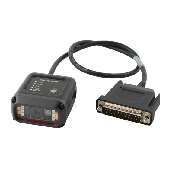
Introduction About This Manual This Reference Manual provides installation and programming instructions for the HF800 fixed mount barcode reader. Product specifications, dimensions, warranty and customer support information are also included. ® Suggest to configure the reader with DataMax Configuration Tool to make the reader working properly. - Page 6 2. Vertical model This vertical model type provide a kind of different way for mounting, which is usually can be used in narrow space in vertical direction. This model provides a Green LED aimer which helps user to locate the central position of the decoding area. Internal Mirror Lens Internal Illuminator...
-
Page 7: Package Contents
Package Contents 1 、 HF800 Fixed Mount Barcode Reader 2 、 Ethernet Pot Cover Appearance Package Model Name Qty. Vertical Horizontal content model model Fixed Mount Reader unit Barcode Reader HF800 Ethernet pot cover ( Assembled on reader ) Accessories Part Name Drawing... - Page 8 12.00+/-0.6VDC, maximum current is 1.25A. The adaptor should co-work with the plug, recommend to buy them both from Honeywell as an assembly. Note: The inside of the DC plug is negative, outside is positive. Recommend to use Honeywell adaptor only.
- Page 9 The 14 Pin connector description: Pin NO. Description Pin NO. Description 1 Vin Power supply 8 GND Power supply ground 2 IN1B External input 1B (Polarity insensitive) 9 O1+ Positive Output 1 3 IN1A External input 1A (Polarity insensitive) 10 O1- Negative Output 1 4 IN2B External input 2B (Polarity insensitive)
-
Page 10: Human Machine Interface
Human Machine Interface HF800 has 5 indicators to show the reader status and a tune button for easy configuration, detail function description as below. Indicators description Train Green/ Red LED. 1, When duration of pressing the Tune button in between 3s and 20s, the led will flick with green and red alternative in 100ms.Then release the button at this time, led will off. -
Page 11: Electrical Characteristics
Electrical Characteristics HF800 D-sub 25pin male connector Power, COM and I/O Connector Pinout Name Function Pin number 9,13 Power supply input(10VDC-30VDC) 7,25 Power supply ground Shield Chassis shield RS232_TX TXD(output) RS232_RX RXD(input) RS232_RTS RTS(output) RS232_CTS CTS(input) IN2A External Input channel 2 A IN2B External Input channel 2 B IN1A... - Page 12 Input Two digital inputs (Input1, Input2) are available, with the protection of 2 polarity insensitive optocouplers. Typical forward voltage of the optocoupler is1.35V, maximum current is 50mA. User should adjust the VDD and the serial resistor to make sure the current is less than 50mA, VDD should be more than 1.35VDC and less than 30VDC.
- Page 13 NPN type IR connected to external I/O+RS232 cable NPN type IR connected to external I/O+RS485/422 cable Typical PNP type IR connection to input2 layout as below, input1 as well, just need to repalce IN2A with IN1A, replace IN2B with IN1B. A series resistor(1Kohm to 1.5Kohm) is recommended to be put between signal and IN2A to limit the current.
-
Page 14: Mechanical Dimensions
HF800 support one 10/100M adaptable Ethernet, DHCP is enabled by default. If disabled, default IP is 192.168.1.110, net mask 255.255.255.0. M12 A coding connector for water proof, user should buy a M12 to RJ45 Ethernet transform cable from Honeywell in accessory list. HF800 Ethernet Connector Pinout Name Function... - Page 15 3. Mounting bracket overall dimensions...
-
Page 16: Optic Characteristics
Optic Characteristics Refer the data in the following table to adjust the installation distance for your application. DOF= L1~L2 Depth of Field (DOF) Symbology Horizontal (L Vertical (L 4mil Code 38 50~80 mm 25-55 mm 5mil Code 39 30~115 mm 25-90 mm 13 mil UPC 40~175 mm... - Page 17 MODEL (internal distance/mm) ( Horizontal angle) ( Vertical angle) HF800HD-1-1H 41.4 32.2 HF800SR-1-1H 42.4 HF800ER-1-1H 31.6 24.4 HF800HD-1-1V 41.4 32.2 HF800SR-1-1V 42.4 HF800ER-1-1V 31.6 24.4...
-
Page 18: Getting Started
Getting Started Mounting and Positioning Using the HF800 mounting brackets you can obtain rotation on the various axes of the reader as shown in the diagrams below: • Mounting screw size : M2.5 Connections Connecting with Ethernet To connect the system in an Ethernet point to point configuration, you need the hardware indicated as below. -
Page 19: Connecting With Rs485
Connecting with RS485 To connect the system in a serial point to point configuration, you need the hardware indicated as below. In this layout, the data is transmitted to the Host from the HF800 RS485/422 interface. Note: the IO connector is combined with the RS485/422 interface, and if the device is not powered by the customer device, a power adaptor is need in this case. -
Page 20: Hardware Requirements
Hardware Requirements ® Typical hardware requirements for a DataMax Client PC are: a. 2.00GHz or faster microprocessor b. 1GB RAM c. 2GB hard disk for 64-bit machines; 1GB hard disk for 32-bit machines d. One 19’’ or larger monitor (optimized for 1280*1024 resolution) Software Requirements Windows Operating System (32 or 64-bit): Windows XP/7/8/10. - Page 21 Privacy statement: Privacy statement:...
- Page 22 Choose destination location: Ready to install program:...
- Page 23 Setup status: Complete:...
-
Page 24: Datamax ® User Interface Overview
Desktop shortcuts: Double-click the desktop shortcut to run it: Note: Tool authority will rely on the PC permission. ® DataMax User Interface Overview Device List Area The device list will be displayed in this area. -
Page 25: Control And Help Panel
Control and Help Panel This area shows “Open Configuration”, “Save Configuration”, “Language”, “Log Level”, “Update Firmware”, “Restart”, “User Guide”. Open and Save Configuration Set Language and Log Update Firmware and Restart User Guide Main Menu and Toolbar Main Menu: Status bar: SN number and Device name ®... -
Page 26: Discover Under Ethernet
Discover under Ethernet ® Open the DataMax Configuration Program, click button, select checkbox Ethernet and click Search button. The Program will automatically search all the connected device in the LAN and list its brief information accordingly. Each item has three parts that users should know. 1 Device name and serial number. -
Page 27: Discover Under Serial Port
2 Device current IP address. ® 3 Connecting status, grey dot means DataMax Configuration Program has not connected to this device yet, green dot means this device has already connected ® to DataMax Configuration Program. If connect to a specified device, double click its item box (or right click and select option connect) If connected to a device successfully, you will see the device information on the right ®... -
Page 28: Device Information Description
If the device is connected successfully, the device information will be showed on the ® right side of the DataMax Configuration Program. Device Information Description ® Select the tab of DataMax , the device information description is shown as follow. Imaging Settings &... -
Page 29: Live View
Live View When connect to the device, the live view window will not show images in default and the window will appear to be dark. Click the button to turn on live view function. Then the images captured by the reader will be shown in the window if it is working. -
Page 30: Statistics
Right click in the Log View, a popup menu will appear, Choose “Save to file” to save the result to specified file. Choose “Clear” to clear all the information in the Log View window. Statistics The “Statistics” panel will show all the current decoding counters. Through it, user can monitor the decoding rate and average decode times. -
Page 31: Aimer & Light
Also in this panel,bank settings could be configured to take effect when reading. In each bank,user could set specific exposure time and gain and choose whether to enable or disable.HF800 support no more than eight banks. If there are more than one enabled banks,reader will switch among different bank settings one by one when reading until read one barcode or timeout occurs. -
Page 32: Auto-Train
Auto-Train HF800 can support Auto-Train function. When execute, it can help to tune the imaging parameters and identify the barcodes in front of the reader’s FOV automatically. This function can help to reduce the distribution time. Auto-Train Tuning Steps: ® 1. -
Page 33: Image Cropping
If failed, reader will give an error beep and a dialog will appear to inform the user. Image Cropping Sometimes the current barcode position was known before searching, if change the search region from the whole image to a specified small region, it will reduce the decoder’s search time and can reduce the decode time as well. -
Page 34: Charts Panel
Charts Panel When the reader is working and live view function is enabled. This panel can demonstrate the statistic values of decode time and good read rate. The axes may look like below images:... -
Page 35: Configurations Loading/Storage
Configurations Loading/Storage ® DataMax allows load and storage configurations form/to pc. Operating steps: 1. Select one device and connect. 2. Click button locate on the left of Devices 3. To save devices configuration to PC: a. Select “Save Configuration to PC” button. b. - Page 36 4. To load pc configuration to device: a. Select “Open Configuration from local PC”. b. Select the file path and the file name with “.cfg” extend name. c. It will notify users that “Load configuration Success”. ® 5. To save DataMax configuration to device, select “Save Configuration to Device”...
-
Page 37: Restore To Default
Restore to Default To return a device to its absolute Factory default parameters it is necessary to use the Restore Factory Defaults Tune. You will be prompted to confirm. All Environment parameters will be restored to Factory default values and any existing configurations stored on the device will be erased. -
Page 38: Communication Interface Setup
Communication Interface Setup Network Setup ® Open DataMax Configuration Program and connect a device first, Click button. If DHCP is enabled, IP address subnet and gateway is not available, the device will get IP address subnet address and gateway automatically by DHCP server. If DHCP is disabled, you can setup static IP address, subnet and gateway Click Ok button and your settings will be saved in the device and activated after device reboot. - Page 39 Right-click on Local Area Connection and click on Properties.
- Page 40 4. Select Internet Protocol Version 4 (TCP/IPv4) and click on Properties. 5. Select "Use the following IP address" and enter the IP address, Subnet Mask, Default Gateway. and DNS server. Click OK and close the Local Area Connection properties window. (Reader default IP address is 192.168.1.110, so make user your PC IP address and reader IP address are in the same network segment)
-
Page 41: Network Grouping (Master/Slave)
Network Grouping (Master/Slave) HF800 support network grouping, user could set maximum 8 readers in a group. Network grouping supports 2 modes: Synchronized mode and Pass-through mode. In Synchronized mode, suggest user to use one trigger source to trigger all the HF800s in the group. In Pass-through mode, all the HF800s could be triggered by one source, or be triggered separately. - Page 42 If the device you selected is Master, you can select Master work mode: 1. Synchronize mode: Master will receive data which from slave devices and processing all the data (data format, sequence) and transmit the overall data through Master’s interface. NOTE: Please make sure that master and slaves share the same symbologies settings, if slave decode and transmit one certain symbology to master which master do not support, master will ignore this symbology and...
-
Page 43: Serial Interface Setup
Serial Interface Setup The Serial interface is used when connecting to the serial port of a PC or terminal. ® Select tab of the DataMax and click the button 1. Baud rate sends the data form the reader to the terminal at the specified rate, the host terminal must be set for the same baud rate as the reader. - Page 44 and punctuation), select 7 data bits. For applications that require use of the full ASCII set, select 8 data bits per character. Default=8. 3. Stop bits sets the stop bits at 1 or 2. Default=1. 4. Parity provides a means of checking character bit patterns for validity. Default=None.
-
Page 45: Operating Mode
Operating Mode Streaming Presentation Mode When in Streaming Presentation Mode, the reader remains on all the time to continuously search for barcodes. The reader’s illumination and aimer can be configured to be on or off. ® To configure the reader to work in this mode, open the DataMax Configuration Program and Connect to the specific device first. -
Page 46: External Trigger Mode
Note: The parameter “Re-read Delay” is also work in this mode. For details, please go to “Streaming Presentation Mode” for reference. External Trigger Mode When in External Trigger Mode, the reader will wait for a trigger signal from external, This signal can be a pulse or a latched electrical level. When the reader detects this signal, it will try to search the barcodes immediately. -
Page 47: Trigger Through Remote Commands
If the delay duration is larger than zero,reader will delay for the user specified time value then trigger the reader. If the delay duration is equal to zero,reader will be triggered immediately. Trigger through remote commands The reader can also be triggered by sending specified ASCII command via serial or network: Activate: SYN T CR (ASCII 22 84 13) Deactivate: SYN U CR (ASCII 22 85 13) -
Page 48: Continuous Mode
One important parameter in this mode is “Trigger Times”, When the value is larger than 1, the reader will repeat the barcode reading activity for specific times. In each reading cycle, the reader will acquire one image and try to search the barcodes contained in it. -
Page 49: Symbologies
Symbologies The reader will be configurable such that the reading of each symbol type can be enabled or disabled individually, and features appropriate to specific symbol types can be controlled. HF800 can choose to support the following symbologies: Aztec Code, Codabar, Codablock A, Codablock F, Code 11, Code 128, Code 39, Code 93, Data Matrix, EAN/JAN-13, EAN/JAN 8, Interleaved 2 of 5, Matrix 2 of 5, MaxiCode, MicroPDF, PDF417, MSI, QR Code, RSS Expanded, RSS Limited, RSS- 14, UPC-A, UPC E, Chinese Sensible(Han Xin) code, Maxicode, DPM code. -
Page 50: Code 11
Code 11 Click the “Code 11” in the left list then all its related parameters will be shown on the right. Redundant times: output the decode result only when got identical barcodes information for specific times. Minimum Length: output the decode result when the symbology length equal or larger than the minimum length. -
Page 51: Code 39
Redundant times: output the decode result only when got identical barcodes information for specific times. Minimum Length: output the decode result when the symbology length equal or larger than the minimum length. Maximum Length: output the decode result when the symbology length equal or shorter than the maximum length. - Page 52 Redundant times: output the decode result only when got identical barcodes information for specific times. Minimum Length: output the decode result when the symbology length equal or larger than the minimum length. Maximum Length: output the decode result when the symbology length equal or shorter than the maximum length.
-
Page 53: Interleaved 2 Of 5
Full ASCII Table DLE $P SP SPACE ‘ DC1 $Q DC2 $R “ DC3 $S DC4 $T NAK $U % /E SYN $V & ETB $W ‘ CAN $X SUB $Z ESC %A < m +M > DEL %T Character pairs /M and /N decode as a minus sign and period respectively. Character pairs /P through /Y decode as 0 through 9. -
Page 54: Codabar
Codabar Click the “Codabar” in the left list then all its related parameters will be shown on the right. Redundant times: output the decode result only when got identical barcodes information for specific times. Minimum Length: output the decode result when the symbology length equal or larger than the minimum length. -
Page 55: Upc-A
Redundant times: output the decode result only when got identical barcodes information for specific times. Minimum Length: output the decode result when the symbology length equal or larger than the minimum length. Maximum Length: output the decode result when the symbology length equal or shorter than the maximum length. -
Page 56: Upc-E
Addenda Required: When Required is set, the HF800 only reads UPC-A bar codes that have addenda. Addenda Separator: When this feature is On, there is a space between the data from the bar code and the data from the addenda. When turned Off, there is no space. -
Page 57: Ean-8
EAN-8 Click the “EAN-8” in the left list then all its related parameters will be shown on the right. Redundant times: output the decode result only when got identical barcodes information for specific times. Check Digit Transmit: This selection allows you to specify whether the check digit should be transmitted at the end of the scanned data or not. -
Page 58: Msi
Redundant times: output the decode result only when got identical barcodes information for specific times. Check Digit Transmit: This selection allows you to specify whether the check digit should be transmitted at the end of the scanned data or not. 2/5 Digit Addenda: This selection adds 2 or 5 digits to the end of all scanned EAN- 13 data. -
Page 59: Gs1 Databar Limited
Minimum Length: output the decode result when the symbology length equal or larger than the minimum length. Maximum Length: output the decode result when the symbology length equal or shorter than the maximum length. GS1 DataBar Limited Click the “GS1 DataBar Limited” in the left list then all its related parameters will be shown on the right. -
Page 60: Stacked Symbologies
Stacked Symbologies Enable/Disable all Stacked symbologies ® Open DataMax Configuration Program and connect the device first. Go to the tab page “Symbologies” and click the “Stacked Linear” sub page. Check the check box “Check All” will enable all the Stacked symbologies present in the list. -
Page 61: Micropdf
MicroPDF Click the “MicroPDF” in the left list then all its related parameters will be shown on the right. Redundant times: output the decode result only when got identical barcodes information for specific times. Minimum Length: output the decode result when the symbology length equal or larger than the minimum length. -
Page 62: 2-D Symbologies
Redundant times: output the decode result only when got identical barcodes information for specific times. Minimum Length: output the decode result when the symbology length equal or larger than the minimum length. Maximum Length: output the decode result when the symbology length equal or shorter than the maximum length. -
Page 63: Maxicode
Redundant times: output the decode result only when got identical barcodes information for specific times. Minimum Length: output the decode result when the symbology length equal or larger than the minimum length. Maximum Length: output the decode result when the symbology length equal or shorter than the maximum length. -
Page 64: Qr Code
QR Code Click the “QR Code” in the left list then all its related parameters will be shown on the right. Redundant times: output the decode result only when got identical barcodes information for specific times. Minimum Length: output the decode result when the symbology length equal or larger than the minimum length. -
Page 65: Hanxin
HanXin Click the “HanXin” in the left list then all its related parameters will be shown on the right. Redundant times: output the decode result only when got identical barcodes information for specific times. Minimum Length: output the decode result when the symbology length equal or larger than the minimum length. -
Page 66: Decoder Configurations
Decoder Configurations This chapter will list most of the decoding related parameters to configure the activity ® of the reader. The “Decoding” Tab page inside the DataMax Configuration Program includes all the related configurations. General Settings Reread Delay This is an important parameter in this mode which sets the time period before the reader can read the same barcode a second time. -
Page 67: Decode Timeout
Decode Timeout This sets the maximum time duration that the reader used to decode each image. DPM Support This setting can enable or disable the support of DPM code. Show No Read When enable this setting, if the reader failed to decode, it will output a string “NR” to notify the user. -
Page 68: Output Sequence Configuration Panel
We can also adjust the items order by click the button After all the items were done, click the button will configure the edited output sequence into the reader. And this sequence will take effect immediately. Output Sequence Configuration Panel To enable the output sequence matching, we should also configure some following settings. - Page 69 Separator This setting is to add separators to the output sequences. Code Sequence This setting is to control the output ordering rule when output the sequence. Random: Barcode result will output randomly. Top-Bottom: Barcode result will output from top to bottom according to their coordination in the image.
-
Page 70: Input/Output Settings
Input/output settings Input Channel settings There are two inputs on the reader, with the protection of 2 polarity insensitive optocouplers: input1 and input2, they work with same functions as external trigger. Its main functions are: acquisition trigger in external trigger mode. By default, input1 and input2 are associated with None polarity, the input signals are fully programmable by the users. -
Page 71: Output Channel Settings
If select Falling edge, set the Operation Mode to Continuous mode, the Falling signal will start decoding barcode, it will stop until read time out or get the right barcode data. Read time out Start decoding Start decoding Output Channel settings Two general purpose outputs are available, with the protection of 2 optocouplers. -
Page 72: Data Editing And Formatting
Data Editing and Formatting Prefix/Suffix Overview When a bar code is scanned, additional information is sent to the host computer along with the barcode data. This group of bar code data and additional, user-defined data is called a “message string”. The selections in this section are used to build the user-defined data into the message string. - Page 73 Enter character in the setting prefixes/suffixes chart box to appear on the output. Default prefix is empty. Default suffix is empty. For example: 1. Select all symbologies...
-
Page 74: Data Format Editor Introduction
2. Use the follow barcode, the data is output as: ABC1234567890ABCDEFGHIJED33 3. Clear prefix and suffix Just delete prefix: ABC or suffix: ED33 Data Format Editor Introduction To use the Data Format Editor to change the device’s output. For example, to insert characters at certain points in barcode data as it is scanned. - Page 75 Code Type Name Insert the name of the bar code’s symbology in the output message, without moving the cursor. Only symbologies with a Honeywell ID are included Code Length Insert the bar code’s length in the output message, without moving the cursor.
-
Page 76: Advance Mode (Command Line)
4. Clear data format Chose the format you want to delete, then click Advance Mode (command Line) To use advance mode: Advance mode is to edit data format by command line, by using command line, more data format can be used more flexibly... -
Page 77: Maintenance
Maintenance Firmware upgrade ® DataMax allows user to upgrade the reader’s firmware. 1. Click the Update Firmware tab. 2. Click “choose file” and select the “. SMOC” file. 3. Click “open” and wait it done. The device will restart automatically after the file transfer is completed. -
Page 78: Trouble Shooting
“POWER” LED is not If using a power adapter, please make sure use the lit. Honeywell recommend power adaptor. If using customer power, please make sure the proper wired with Vin and GND on the connector. See detail information as on page 11... - Page 79 If device is connected via serial port, be sure to select correct parameters (Data Bits/Stop Bits/Parity). Reading failure - Tune the Acquisition Delay on Trigger, if the moving code is out of the reader field of view; - Set the streaming presentation/presentation Operating Mode if no external trigger source is available;...
-
Page 80: Customer Support
#).You should do this prior to returning the product. Limited Warranty Honeywell International Inc. (“HII”) warrants its products to be free from defects in materials and workmanship and to conform to HII’s published specifications applicable to the products purchased at the time of shipment. This warranty does not cover any HII product which is (i) improperly installed or used;... - Page 81 EXCEPT AS MAY BE OTHERWISE PROVIDED BY APPLICABLE LAW, THE FOREGOING WARRANTY IS IN LIEU OF ALL OTHER COVENANTS OR WARRANTIES, EITHER EXPRESSED OR IMPLIED, ORAL OR WRITTEN, INCLUDING, WITHOUT LIMITATION, ANY IMPLIED WARRANTIES OF MERCHANTABILITY OR FITNESS FOR A PARTICULAR PURPOSE, OR NON- INFRINGEMENT.
-
Page 82: Appendix A
Appendix A Enable Network DHCP, function will take effect after restart the device. Disable Network DHCP, function will take effect after restart the device. Reboot the reader HF800-ENUS-UG Rev A...
Need help?
Do you have a question about the HF800 Series and is the answer not in the manual?
Questions and answers