Table of Contents
Advertisement
Advertisement
Table of Contents

Related Manuals for Honeywell 7120 Orbit


Summary of Contents for Honeywell 7120 Orbit
- Page 1 7120 Orbit™ Presentation Laser Scanner User’s Guide...
- Page 2 Disclaimer Honeywell International Inc. (“HII”) reserves the right to make changes in specifications and other information contained in this document without prior notice, and the reader should in all cases consult HII to determine whether any such changes have been made. The information in this publication does not represent a commitment on the part of HII.
-
Page 3: Table Of Contents
ABLE OF ONTENTS Introduction Product Overview ..................... 1 Scanner and Accessories ................. 2 Scanner Components ..................4 Cable Removal ....................4 Caution and Serial Number Labels ..............5 Maintenance ..................... 5 Mounting Specifications ................... 6 Installation RS232, or Light Pen ..................7 RS485 ...................... - Page 4 ABLE OF ONTENTS Applications and Protocols ................. 24 Scanner Configuration ..................25 Configuration Modes ..................25 Bar Codes ....................25 MetroSet2 ....................25 Serial Configuration ..................25 Upgrading the Firmware ..................26 Scanner and Cable Terminations Scanner Pinout Connections ................27 Cable Connector Configurations (Host End) ..........
-
Page 5: Product Overview
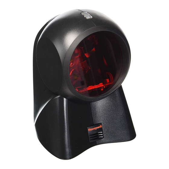
NTRODUCTION ™ Orbit is an aggressive, omnidirectional laser bar code scanner ideal for use in retail, convenience, liquor and specialty stores Designed to be lightweight and rugged, Orbit’s small size makes it ideal for applications where counter space is limited. The 7120 unique contoured shape allows it to be picked-up and used as a hand-held scanner when scanning large or bulky items. -
Page 6: Scanner And Accessories
NTRODUCTION Scanner and Accessories ASIC OMPONENTS Part No. Description MS7120 Orbit Presentation Laser Bar Code Scanner 7120 Orbit Presentation Laser Bar Code Scanner 00-02282x User’s Guide 00-02407x MetroSelect™ Configuration Guide * Guides also available for download at www.honeywellaidc.com. PTIONAL CCESSORIES Part No. - Page 7 NTRODUCTION Scanner and Accessories PTIONAL CCESSORIES Part No. Description RS485 Applications MVC** MVC Cable ±12VDC to +5.2VDC Contact a customer service representative for additional information on the MVC cable series and the host connections available. Keyboard Wedge PowerLink Cable 59-59002x-3 straight cord, short strain relief Stand Alone Keyboard PowerLink Cable 59-59020x-3...
-
Page 8: Scanner Components
NTRODUCTION Scanner Components ESCRIPTION White LED (see page 12) Blue LED (see page 12) Red Output Window (Laser Aperture) Speaker (see page 12) Pin Hole for Cable Release 10-Pin RJ45, Female Socket (see page 28) Adjustable Scan Head, 30° Figure 1. Scanner Components Cable Removal Locate the small ‘pin-hole’... -
Page 9: Caution And Serial Number Labels
NTRODUCTION Caution and Serial Number Labels Figure 3. Labeling Locations on the Bottom of the Scanner and Examples Caution To maintain compliance with applicable standards, all circuits connected to the scanner must meet the requirements for SELV (Safety Extra Low Voltage) according to EN/IEC 60950-1. To maintain compliance with standard CSA C22.2 No. -
Page 10: Mounting Specifications
NTRODUCTION Mounting Specifications Optional Wall/Counter Mount Item Description Qty. Locking Plate, 50-50302 Base Cover, 50-50301 #7 x 1.00" Wood Screw, 18-18013 M3 x 8 mm Flathead Screw, 18-18004 Figure 4. Kit Components Drill three #39 pilot holes. Note the position Orbit will rest (see Figure 5). -
Page 11: Installation
Powering the 7120 directly from the host device can cause interference with the operation of the scanner or the computer. Not all computers supply the same current. For this reason, Honeywell recommends using an external power supply. For additional information contact a Honeywell customer service representative. -
Page 12: Rs485
NSTALLATION RS485 Turn off the host device. Plug the male 10-pin RJ45 end of the MVC cable into the 10-pin socket on the 7120. Connect the other end of the MVC cable to the host device. Turn on the host device. Figure 10. -
Page 13: Keyboard Wedge
Not all computers supply the same current through the keyboard port. For this reason, Honeywell recommends using an external power supply. For additional information contact a customer service representative. -
Page 14: Stand-Alone Keyboard Wedge
Not all computers supply the same current through the keyboard port. For this reason, Honeywell recommends using an external power supply. For additional information contact a customer service representative. -
Page 15: Full Speed Usb
NSTALLATION Full Speed USB Turn off the host device. Plug the male 10-pin RJ45 end of the USB cable into the 10-pin socket on the 7120. Plug the other end of the USB interface cable into the host device’s USB port. Turn on the host device. -
Page 16: Scanner Operation
CANNER PERATION Audible Indicators When the 7120 is in operation, it provides audible feedback to indicate the status of the scanner. Eight settings are available for the tone of the beep (normal, six alternate tones and no tone). For instructions on how to change the tone of the beeper, refer to the MetroSelect Configuration Guide (00-02407). -
Page 17: Visual
CANNER PERATION Visual Indicators The 7120 is equipped with a blue and a white LED that indicates the scanner’s state and the status of the current scan when the unit is in operation. Figure 14. LED Location No LEDs The LEDs will not be illuminated if the scanner is not receiving power from the host or transformer. -
Page 18: Failure
CANNER PERATION Failure Mode Indicators Flashing Blue with One Razzberry Tone This indicates that the scanner has experienced a laser subsystem failure. Return the unit to an authorized service center for repair. Synchronized Flashing of Blue and White with Two Razzberry Tones This indicates that the scanner has experienced a motor failure. -
Page 19: Depth Of Field Specifications
CANNER PERATION Depth of Field Specifications* Normal Scan Zone Specifications are based on a 0.33 mm (13 mil) bar code. Figure 15. 7120 Normal Depth of Field Reduced Scan Zone Specifications are based on a 0.33 mm (13 mil) bar code. Figure 16. -
Page 20: Depth Of Field By Bar Code Element Width
CANNER PERATION Depth of Field by Bar Code Element Width* Normal Scan Zone INIMUM LEMENT IDTH mils Figure 17. Normal Scan Zone by Bar Code Element Width * All specifications are subject to change without notice. -
Page 21: Reduced Scan Zone
CANNER PERATION Depth of Field by Bar Code Element Width* Reduced Scan Zone INIMUM LEMENT IDTH mils Figure 18. Reduced Scan Zone by Bar Code Element Width * All specifications are subject to change without notice. -
Page 22: Troubleshooting Guide
ROUBLESHOOTING UIDE The following guide is for reference purposes only. Contact a customer service representative to preserve the limited warranty terms on page 33. Symptoms Possible Cause(s) Solution All Interfaces During power up the unit There is a non-volatile Contact a customer service beeps three RAM failure. - Page 23 ROUBLESHOOTING UIDE Symptoms Possible Cause(s) Solution All Interfaces UPC/EAN, Code 39, Interleaved The unit is trying to 2 of 5, Code 93, Code 128 and scan a particular Codabar are enabled by default. symbology that is not Verify that the type of bar code enabled.
- Page 24 ROUBLESHOOTING UIDE Symptoms Possible Cause(s) Solution All Interfaces The bar code may Check if it is a check digit, have been printed character or border problem. incorrectly. Scanner beeps at some bar The scanner is not Check if check digits are set codes and NOT configured correctly for for others of the...
- Page 25 ROUBLESHOOTING UIDE Symptoms Possible Cause(s) Solution RS232 Only The host is The scanner and host Check that the scanner and the receiving data may not be configured host are configured for the same but the data does for the same interface. interface.
-
Page 26: Design Specifications
ESIGN PECIFICATIONS 7120 Operational Light Source: Visible Laser Diode (VLD) @ 650 nm Laser Power: Less than 1 mW average Max Optical Power: 10 mW Embedded Laser: Wavelength: 650 nm Normal Depth of Field: 0 mm – 215 mm 0.33 mm (13 mil) bar code Reduced Depth of Field: 0 mm –... - Page 27 ESIGN PECIFICATIONS 7120 Electrical Voltage Supply: 5VDC ± 0.25V Operating Power: 0.9 W Standby Power: 0.85 W Operating Current: 180 mA typical at 5VDC Standby Current: 170 mA typical at 5VDC DC Transformers: Class II; 5.2VDC @ 1A For regulatory compliance information, see pages 30 - 32. Environmental Operating Temperature: -20°C to 40°C (-4°F to 104°F)
-
Page 28: Applications And Protocols
The 7120 scanner with built-in PC Keyboard Wedge Interface is designed to be used for keyboard emulation only. Many RS232 configurable functions (e.g. formatting) available in other Honeywell scanners are also available as keyboard wedge functions. The following are the most important selectable options specific to the keyboard wedge. -
Page 29: Scanner Configuration
CANNER ONFIGURATION ONFIGURATION ODES The 7120* Series scanner has three modes of configuration. • Bar Codes The 7120 can be configured by scanning the bar codes located in the MetroSelect Configuration Guide. This manual is available for download at www.honeywellaidc.com. •... -
Page 30: Upgrading The Firmware
PGRADING THE IRMWARE The Orbit 7120 is part of Honeywell’s line of scanners with flash upgradeable firmware. The upgrade process requires, a new firmware file supplied to the customer by a customer service representative and Honeywell’s MetroSet2 software . -
Page 31: Scanner And Cable Terminations
CANNER AND ABLE ERMINATIONS Scanner Pinout Connections The 7120 scanner interfaces terminate to a 10-pin modular socket. The serial number label indicates the interface enabled when the scanner is shipped from the factory. Figure 19. MS7120-47 Keyboard Wedge MS7120-41 and Stand-Alone Keyboard RS232C and Light Pen Emulation Function Function... -
Page 32: Cable Connector Configurations (Host End)
CANNER AND ABLE ERMINATIONS Cable Connector Configurations (Host End) “Standard” PowerLink Cable 59-59000 -3 straight Function Shield Ground RS232 Transmit Output RS232 Receive Input DTR Input/Light Pen Source Power/Signal Ground Light Pen Data 9-Pin D-Type Connector CTS Input RTS Output +5VDC USB Power/Communication Cable 54-54213... - Page 33 PC Clock No Connect Honeywell will supply an adapter cable with a 5-pin DIN male connector on one end and a 6-pin mini DIN female connector on the other. According to the termination required, connect the appropriate end of the adapter cable to the PowerLink cable, leaving the necessary termination exposed for connecting to the keyboard and the keyboard port on the PC.
-
Page 34: Regulatory Compliance
EGULATORY OMPLIANCE Safety ITE Equipment IEC 60950-1 Second Edition EN 60950-1 Second Edition Laser Laser Class 1: IEC 60825-1: Second Edition, 2007 EN 60825-1: Second Edition, 2007 IEC 62471: Exempt Risk Group Caution Use of controls or adjustments or performance of procedures other than those specified herein may result in hazardous laser light exposure. -
Page 35: Emc
EGULATORY OMPLIANCE Attenzione L’utilizzo di sistemi di controllo, di regolazioni o di procedimenti diversi da quelli descritti nel presente Manuale può provocare delle esposizioni a raggi laser rischiose. Il cliente non deve assolutamente tentare di riparare egli stesso lo scanner laser. Non guardate mai il raggio laser, anche se credete che lo scanner non sia attivo. - Page 36 EGULATORY OMPLIANCE Attenzione Questo e’ un prodotto di classe A. Se usato in vicinanza di residenze private potrebbe causare interferenze radio che potrebbero richiedere all’utilizzatore opportune misure. Attention Ce produit est de classe “A”. Dans un environnement domestique, ce produit peut être la cause d’interférences radio.
-
Page 37: Limited Warranty
IMITED ARRANTY Honeywell International Inc. ("HII") warrants its products and optional accessories to be free from defects in materials and workmanship and to conform to HII’s published specifications applicable to the products purchased at the time of shipment. This warranty does not cover any HII product which is (i) improperly installed or used;... -
Page 38: Index
NDEX indicator audible ..4, 12–14, 18–21, 22 AC ........see power failure ........14 accessories ....... 2, 3 visual ... 4, 12–14, 18–21, 22 adapter ........9, 29 interface ........ 22, 24 Keyboard Wedge ..1, 3, 9, 21 Light Pen ....... - Page 39 NDEX storage ........23 razz ......see indicator repair ........... 34 tone ......... 1, 12 RMA ..........34 transformer ...... see power RS232 ......see interface troubleshooting ..... 18–21 RS485 ......see interface UL ......see compliance safety ........30, 32 USB ......
-
Page 40: Customer Support
For our latest contact information, please check our website at the link above. Product Service and Repair Honeywell International Inc. provides service for all of its products through service centers throughout the world. To obtain warranty or non-warranty service, please visit www.honeywellaidc.com... - Page 44 Honeywell Scanning & Mobility 9680 Old Bailes Road Fort Mill, SC 29707 www.honeywellaidc.com 00-02282 Rev G 1/14...
Need help?
Do you have a question about the 7120 Orbit and is the answer not in the manual?
Questions and answers