Table of Contents
Advertisement
Quick Links
Extron Electronics, USA
Extron Electronics, Europe
1230 South Lewis Street
Beeldschermweg 6C
Anaheim, CA 92805
3821 AH Amersfoort
USA
The Netherlands
714.491.1500
+31.33.453.4040
www.extron.com
Fax 714.491.1517
Fax +31.33.453.4050
© 2006 Extron Electronics. All rights reserved.
Extron Electronics, Asia
Extron Electronics, Japan
135 Joo Seng Road, #04-01
Kyodo Building
PM Industrial Building
16 Ichibancho
Singapore 368363
Chiyoda-ku, Tokyo 102-0082 Japan
+65.6383.4400
+81.3.3511.7655
Fax +65.6383.4664
Fax +81.3.3511.7656
User's Manual
DVI to Analog RGB Video Interface
DVI-RGB 150
68-1247-01 Rev. A
07 06
Advertisement
Table of Contents

Subscribe to Our Youtube Channel
Related Manuals for Extron electronics DVI-RGB 150


Summary of Contents for Extron electronics DVI-RGB 150
- Page 1 Anaheim, CA 92805 3821 AH Amersfoort PM Industrial Building 16 Ichibancho 07 06 The Netherlands Singapore 368363 Chiyoda-ku, Tokyo 102-0082 Japan 714.491.1500 +31.33.453.4040 +65.6383.4400 +81.3.3511.7655 www.extron.com Fax 714.491.1517 Fax +31.33.453.4050 Fax +65.6383.4664 Fax +81.3.3511.7656 © 2006 Extron Electronics. All rights reserved.
- Page 2 Reparaciones/mantenimiento • Solicitar siempre los servicios técnicos de personal califi cado. En el interior no hay partes a las que el usuario deba acceder. Para evitar use. In no event will Extron Electronics be liable for direct, indirect, or consequential riesgo de electrocución, no intentar personalmente la reparación/mantenimiento...
-
Page 4: Table Of Contents
Front Panel Controls and Indicator ........2-8 Operation ..................2-9 DVI Connector Pin Assignments ......... 2-10 Appendix A • Reference Information ......A-1 Specifi cations ................A-2 Part Numbers ................A-5 Included Parts .................A-5 Mounting accessories ............A-5 Cables/adapters ..............A-5 DVI-RGB 150 • Table of Contents... - Page 5 Table of Contents, cont'd DVI-RGB 150 Chapter One Introduction 68-1247-01 Rev. A 07 06 All trademarks mentioned in this manual are the properties of their respective owners. DVI-RGB 150 • Table of Contents...
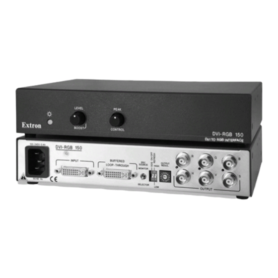
- Page 6 Introduction The Extron DVI-RGB 150 DVI to analog RGB video interface DVI-RGB 150 converts DVI digital video to analog RGB video. The interface accepts a single link of digital-only Digital Visual Interface (DVI-D) video from a computer, or other digital video source device, on a standard 29-pin female DVI-I connector.
-
Page 7: Installation And Operation
Installation and Operation Installation Overview 6" Deep Rack Shelf 1/2 Rack Width Front False To install and set up an Extron DVI-RGB 150 for operation, Faceplate follow these steps: Turn off all of the equipment. Ensure that the video sources and the output display are all turned off and disconnected from the power source. -
Page 8: Under-Desk Mounting
Using the four wood screws provided, attach the brackets Slide the unit slightly in or out, then tighten all four screws to the mounting surface. to secure the unit in place (fi gure 2-3). DVI-RGB 150 • Installation and Operation DVI-RGB 150 • Installation and Operation... -
Page 9: Rear Panel Connections And Controls
Remove the transmitter or receiver from inside the the DDC channel between the direct digital video source furniture. and the built-in DVI-RGB 150 DDC logic. c. Tighten the screws. Output Resolution rotary switch — If the DDC Source OUTPUT RESOL. -
Page 10: Front Panel Controls And Indicator
Power LED — The two-tone Power LED lights yellow or green: The DVI-RGB 150 cannot respond to the HDCP decryption key. Yellow when the DVI-RGB 150 is receiving power but no DVI input signal is applied. When the DVI input is HDCP encrypted, the DVI-RGB 150's RGB output is blank. -
Page 11: Dvi Connector Pin Assignments
DVI-RGB 150 to fail. The missing connectors on the included DVI cable are not required for the single link of DVI-D data supported by the DVI-RGB 150. These pins are grayed out on the following Reference Information table. -
Page 12: Appendix A • Reference Information
Resolution selector resolutions and rates Specifi cations Setting Resolution Refresh Low Refresh High Video 640x480 60 Hz 75 Hz The DVI-RGB 150 converts a single link DVI signal to an 800x600 60 Hz 75 Hz analog RGB signal. 852x480 60 Hz... -
Page 13: Part Numbers
Power ..........100 VAC to 240 VAC, 50/60 Hz, 25 watts, Included Parts internal, autoswitchable. These items are included in each order for a DVI-RGB 150: Temperature/humidity ....Storage: -40 to +158 °F (-40 to +70 °C) / 10% to 90%, noncondensing... - Page 14 Reference Information DVI-RGB 150 • Reference Information...
Need help?
Do you have a question about the DVI-RGB 150 and is the answer not in the manual?
Questions and answers